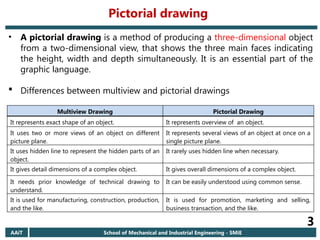
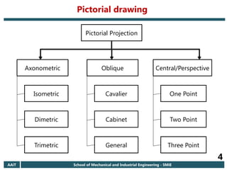
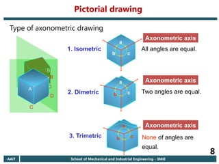
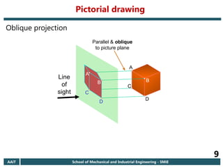
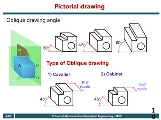
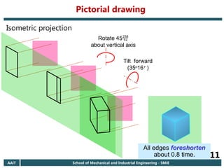
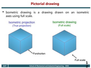
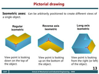
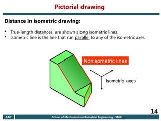
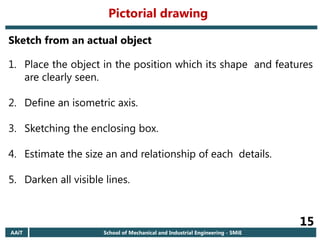
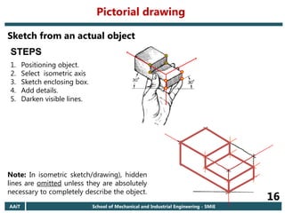
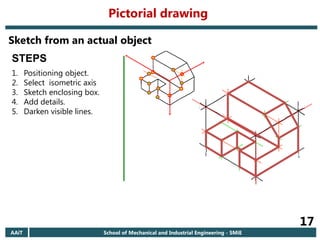
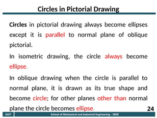
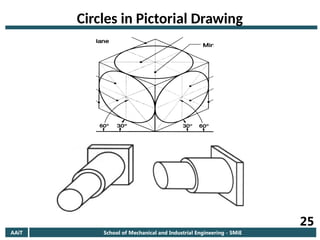
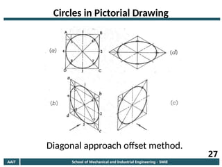
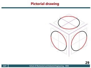
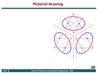
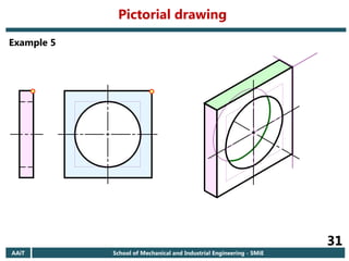
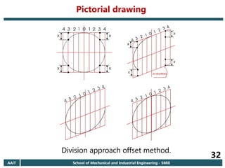
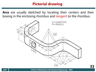
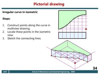
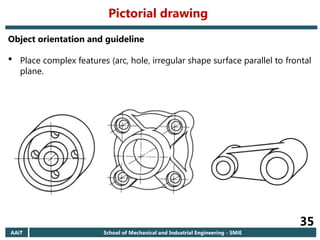
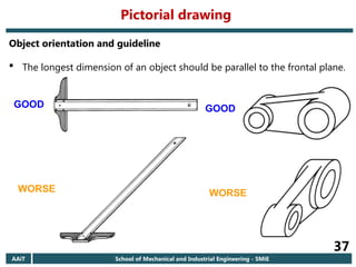
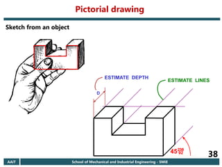
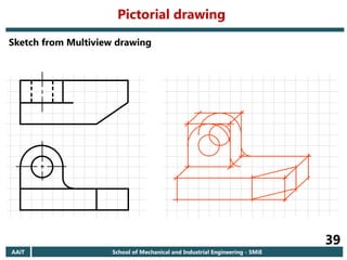
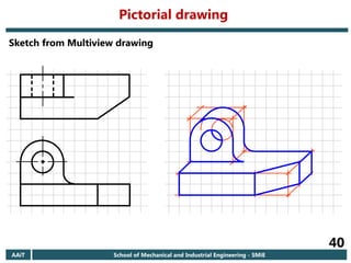
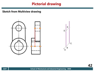
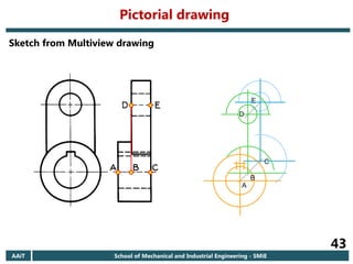
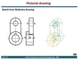
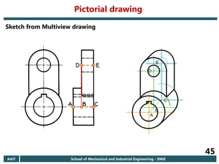
Addis Ababa University
Addis Ababa Institute of Technology
School of Mechanical & Industrial Engineering
By Tadele Libay
Chapter 4
Pictorial drawings
Course objective
AAiT School of Mechanical and Industrial Engineering - SMiE
2
At the end of this chapter students are;
 able to explain the difference between an axonometric and an oblique
projection.
 able to explain the difference between an isometric projection and an
isometric drawing/sketch.
 able to create an isometric and oblique sketches from an actual object
and multiview drawing.
Pictorial drawing
AAiT School of Mechanical and Industrial Engineering - SMiE
3
• A pictorial drawing is a method of producing a three-dimensional object
from a two-dimensional view, that shows the three main faces indicating
the height, width and depth simultaneously. It is an essential part of the
graphic language.
 Differences between multiview and pictorial drawings
Multiview Drawing Pictorial Drawing
It represents exact shape of an object. It represents overview of an object.
It uses two or more views of an object on different
picture plane.
It represents several views of an object at once on a
single picture plane.
It uses hidden line to represent the hidden parts of an
object.
It rarely uses hidden line when necessary.
It gives detail dimensions of a complex object. It gives overall dimensions of a complex object.
It needs prior knowledge of technical drawing to
understand.
It can be easily understood using common sense.
It is used for manufacturing, construction, production,
and the like.
It is used for promotion, marketing and selling,
business transaction, and the like.
Pictorial drawing
AAiT School of Mechanical and Industrial Engineering - SMiE
4
Pictorial Projection
Axonometric Oblique Central/Perspective
Isometric
Dimetric
Trimetric
Cavalier
Cabinet
General
One Point
Two Point
Three Point
Pictorial drawing
AAiT School of Mechanical and Industrial Engineering - SMiE
5
 Axonometric projection is a projected view in which the lines of sight are perpendicular to
the plane of projection, but the three faces of a rectangular object are all inclined to the plane
of projection.
 Isometric projection: The receding lines are drawn at 300 from the horizontal and the others
are vertical. Consider a cubic object, the three principal faces and axes are equally inclined to
the plane of projection.
 Dimetric projection: Two of the principal faces and axes are equally inclined to the plane of
projection.
 Trimetric projection: All three principal faces and axes make different angles with the plane
of projection.
 Oblique projection: the projectors are oblique to the plane of projection but parallel to each
other, and one of the principal face (usually front view) of the object is generally parallel to the
plane of projection. The receding line is drawn at 300, 450 and 600 from the horizontal.
 Cavalier: All lines of an object are drawn in their true length.
 Cabinet: Lines on the receding axis are shortened by half.
Pictorial drawing
AAiT School of Mechanical and Industrial Engineering - SMiE
6
 Central/perspective projection is the most
realistic three-dimensional view of all the pictorial
projections, because it portrays the object in a
manner that is most similar to how the human eye
perceives the visual world.
 Horizon: an imaginary horizontal line taken at eye
level.
 Vanishing point (VP): a point on the horizon
where receding lines converge.
 One point: have one vanishing point.
 Two point: have two vanishing point.
 Three point: have three vanishing point.
AAiT School of Mechanical and Industrial Engineering - SMiE
7
A
B
C
D
Parallel & normal
to picture plane
Line
of
sight
A
B
C
D
Axonometric drawing
Pictorial drawing
AAiT School of Mechanical and Industrial Engineering - SMiE
8
Type of axonometric drawing
a
b c
2. Dimetric Two angles are equal.
b
a
c
3. Trimetric None of angles are
equal.
a
b c
1. Isometric All angles are equal.
A
B
C
D
A
B
C
D
Axonometric axis
Axonometric axis
Axonometric axis
Pictorial drawing
AAiT School of Mechanical and Industrial Engineering - SMiE
9
A
B
C
D
Line
of
sight
Parallel & oblique
to picture plane
A
D
C
B
Oblique projection
Pictorial drawing
AAiT School of Mechanical and Industrial Engineering - SMiE
1
0
A
D
C
B
B
C D
A
Oblique drawing angle
30o
45o 60o
Type of Oblique drawing
45o
45o
1) Cavalier 2) Cabinet
Full
scale Half
scale
Pictorial drawing
AAiT School of Mechanical and Industrial Engineering - SMiE
11
Rotate 45
about vertical axis
Tilt forward
(35o
16’)
All edges foreshorten
about 0.8 time.
Isometric projection
Pictorial drawing
AAiT School of Mechanical and Industrial Engineering - SMiE
1
2
 Isometric drawing is a drawing drawn on an isometric
axes using full scale.
Isometric projection
(True projection)
Isometric drawing
(Full scale)
Forshorten
Full scale
Pictorial drawing
AAiT School of Mechanical and Industrial Engineering - SMiE
13
Isometric axes: can be arbitrarily positioned to create different views of
a single object.
Regular
isometric
Reverse axis
isometric
Long axis
isometric
View point is looking
down on the top of
the object.
View point is looking
up on the bottom of
the object.
View point is looking
from the right (or left)
of the object.
Pictorial drawing
AAiT School of Mechanical and Industrial Engineering - SMiE
14
Distance in isometric drawing:
 True-length distances are shown along isometric lines.
 Isometric line is the line that run parallel to any of the isometric axes.
Isometric axes
Nonisometric lines
Pictorial drawing
AAiT School of Mechanical and Industrial Engineering - SMiE
15
1. Place the object in the position which its shape and features
are clearly seen.
2. Define an isometric axis.
3. Sketching the enclosing box.
4. Estimate the size an and relationship of each details.
5. Darken all visible lines.
Sketch from an actual object
Pictorial drawing
AAiT School of Mechanical and Industrial Engineering - SMiE
16
Sketch from an actual object
STEPS
1. Positioning object.
2. Select isometric axis
3. Sketch enclosing box.
4. Add details.
5. Darken visible lines.
Note: In isometric sketch/drawing), hidden
lines are omitted unless they are absolutely
necessary to completely describe the object.
Pictorial drawing
AAiT School of Mechanical and Industrial Engineering - SMiE
17
Sketch from an actual object
STEPS
1. Positioning object.
2. Select isometric axis
3. Sketch enclosing box.
4. Add details.
5. Darken visible lines.
Pictorial drawing
AAiT School of Mechanical and Industrial Engineering - SMiE
18
Sketch from an actual object: Oblique
STEPS
1. Positioning object.
2. Select oblique axis
3. Sketch enclosing box.
4. Add details.
5. Darken visible lines.
Pictorial drawing
AAiT School of Mechanical and Industrial Engineering - SMiE
19
Sketch from Multiview drawing
 Interpret the meaning of lines/areas in multiview drawing.
 Locate the lines or surfaces relative to isometric axis.
Pictorial drawing
AAiT School of Mechanical and Industrial Engineering - SMiE
20
Example 1: Object has only normal surfaces
Front View
Top View
Side View
Bottom View
Bottom
Front
Side
Side
Front
Top
Regular
Reverse
W
D
H
H
D
W
Pictorial drawing
AAiT School of Mechanical and Industrial Engineering - SMiE
21
Example 2: Object has inclined surfaces
W
H
q
D
y
x Front View
y
x
Nonisometric line
Pictorial drawing
AAiT School of Mechanical and Industrial Engineering - SMiE
22
Example 3: Object has inclined surfaces
Nonisometric line
A
A x
y
x
x
B
B
A
B
C
C
C
x
y
Pictorial drawing
23
Example 4:
A
A
B
B
C D
E
D
E
F
F
x
y
Front View
Regular
C
Reverse
Pictorial drawing
AAiT School of Mechanical and Industrial Engineering - SMiE
24
Circles in Pictorial Drawing
Circles in pictorial drawing always become ellipses
except it is parallel to normal plane of oblique
pictorial.
In isometric drawing, the circle always become
ellipse.
In oblique drawing when the circle is parallel to
normal plane, it is drawn as its true shape and
become circle; for other planes other than normal
plane the circle becomes ellipse.
AAiT School of Mechanical and Industrial Engineering - SMiE
25
Circles in Pictorial Drawing
AAiT School of Mechanical and Industrial Engineering - SMiE
26
Circles in Pictorial Drawing
Methods to Draw Ellipse:
There are two method namely, offset method
and four center method.
The offset method can be diagonal approach
and division approach.
AAiT School of Mechanical and Industrial Engineering - SMiE
27
Circles in Pictorial Drawing
Diagonal approach offset method.
AAiT School of Mechanical and Industrial Engineering - SMiE
28
Circles in Pictorial Drawing
The four center method as its name indicates uses four center
to draw an ellipse. It is efficient method.
Steps in Four Center Method:
1. Draw a rhombus using the diameter of a circle.
2. Construct perpendicular bisecting lines from each side of
rhombus.
3. Draw lines from obtuse angle corners to opposite side of
rhombus by intersecting the midpoint.
4. Locate the four centers.
5. Draw the arcs with this centers and tangent to rhombus.
AAiT School of Mechanical and Industrial Engineering - SMiE
29
Pictorial drawing
AAiT School of Mechanical and Industrial Engineering - SMiE
30
Pictorial drawing
AAiT School of Mechanical and Industrial Engineering - SMiE
31
Example 5
Pictorial drawing
AAiT School of Mechanical and Industrial Engineering - SMiE
32
Division approach offset method.
Pictorial drawing
AAiT School of Mechanical and Industrial Engineering - SMiE
33
Arcs are usually sketched by locating their centers and then
boxing in the enclosing rhombus and tangent to the rhombus.
Pictorial drawing
AAiT School of Mechanical and Industrial Engineering - SMiE
34
Irregular curve in isometric
Steps:
1. Construct points along the curve in
multiview drawing.
2. Locate these points in the isometric
view.
3. Sketch the connecting lines.
Pictorial drawing
AAiT School of Mechanical and Industrial Engineering - SMiE
35
Object orientation and guideline
 Place complex features (arc, hole, irregular shape surface parallel to frontal
plane.
Pictorial drawing
AAiT School of Mechanical and Industrial Engineering - SMiE
36
Object orientation and guideline
 The longest dimension of an object should be parallel to the frontal plane.
Pictorial drawing
AAiT School of Mechanical and Industrial Engineering - SMiE
37
Object orientation and guideline
 The longest dimension of an object should be parallel to the frontal plane.
GOOD
WORSE
GOOD
WORSE
Pictorial drawing
AAiT School of Mechanical and Industrial Engineering - SMiE
38
Sketch from an object
D
45
ESTIMATE DEPTH
ESTIMATE LINES
Pictorial drawing
AAiT School of Mechanical and Industrial Engineering - SMiE
39
Sketch from Multiview drawing
Pictorial drawing
AAiT School of Mechanical and Industrial Engineering - SMiE
40
Sketch from Multiview drawing
Pictorial drawing
AAiT School of Mechanical and Industrial Engineering - SMiE
41
Sketch from Multiview drawing
Pictorial drawing
AAiT School of Mechanical and Industrial Engineering - SMiE
42
Sketch from Multiview drawing
A
B
C
D
E
Pictorial drawing
AAiT School of Mechanical and Industrial Engineering - SMiE
43
Sketch from Multiview drawing
A
B
C
D
E
Pictorial drawing
AAiT School of Mechanical and Industrial Engineering - SMiE
44
Sketch from Multiview drawing
A
B
D
E
C
Pictorial drawing
AAiT School of Mechanical and Industrial Engineering - SMiE
45
Sketch from Multiview drawing
A
B
D
E
C
Pictorial drawing
AAiT School of Mechanical and Industrial Engineering - SMiE
46
Hidden Lines in Pictorial Drawing
Pictorial drawing
AAiT School of Mechanical and Industrial Engineering - SMiE
47
Hidden Lines in Pictorial Drawing
Pictorial drawing

Chapter 04 Pictorial Drawings engineering drawing.pptx

  • 1.
    Addis Ababa University AddisAbaba Institute of Technology School of Mechanical & Industrial Engineering By Tadele Libay Chapter 4 Pictorial drawings
  • 2.
    Course objective AAiT Schoolof Mechanical and Industrial Engineering - SMiE 2 At the end of this chapter students are;  able to explain the difference between an axonometric and an oblique projection.  able to explain the difference between an isometric projection and an isometric drawing/sketch.  able to create an isometric and oblique sketches from an actual object and multiview drawing.
  • 3.
    Pictorial drawing AAiT Schoolof Mechanical and Industrial Engineering - SMiE 3 • A pictorial drawing is a method of producing a three-dimensional object from a two-dimensional view, that shows the three main faces indicating the height, width and depth simultaneously. It is an essential part of the graphic language.  Differences between multiview and pictorial drawings Multiview Drawing Pictorial Drawing It represents exact shape of an object. It represents overview of an object. It uses two or more views of an object on different picture plane. It represents several views of an object at once on a single picture plane. It uses hidden line to represent the hidden parts of an object. It rarely uses hidden line when necessary. It gives detail dimensions of a complex object. It gives overall dimensions of a complex object. It needs prior knowledge of technical drawing to understand. It can be easily understood using common sense. It is used for manufacturing, construction, production, and the like. It is used for promotion, marketing and selling, business transaction, and the like.
  • 4.
    Pictorial drawing AAiT Schoolof Mechanical and Industrial Engineering - SMiE 4 Pictorial Projection Axonometric Oblique Central/Perspective Isometric Dimetric Trimetric Cavalier Cabinet General One Point Two Point Three Point
  • 5.
    Pictorial drawing AAiT Schoolof Mechanical and Industrial Engineering - SMiE 5  Axonometric projection is a projected view in which the lines of sight are perpendicular to the plane of projection, but the three faces of a rectangular object are all inclined to the plane of projection.  Isometric projection: The receding lines are drawn at 300 from the horizontal and the others are vertical. Consider a cubic object, the three principal faces and axes are equally inclined to the plane of projection.  Dimetric projection: Two of the principal faces and axes are equally inclined to the plane of projection.  Trimetric projection: All three principal faces and axes make different angles with the plane of projection.  Oblique projection: the projectors are oblique to the plane of projection but parallel to each other, and one of the principal face (usually front view) of the object is generally parallel to the plane of projection. The receding line is drawn at 300, 450 and 600 from the horizontal.  Cavalier: All lines of an object are drawn in their true length.  Cabinet: Lines on the receding axis are shortened by half.
  • 6.
    Pictorial drawing AAiT Schoolof Mechanical and Industrial Engineering - SMiE 6  Central/perspective projection is the most realistic three-dimensional view of all the pictorial projections, because it portrays the object in a manner that is most similar to how the human eye perceives the visual world.  Horizon: an imaginary horizontal line taken at eye level.  Vanishing point (VP): a point on the horizon where receding lines converge.  One point: have one vanishing point.  Two point: have two vanishing point.  Three point: have three vanishing point.
  • 7.
    AAiT School ofMechanical and Industrial Engineering - SMiE 7 A B C D Parallel & normal to picture plane Line of sight A B C D Axonometric drawing Pictorial drawing
  • 8.
    AAiT School ofMechanical and Industrial Engineering - SMiE 8 Type of axonometric drawing a b c 2. Dimetric Two angles are equal. b a c 3. Trimetric None of angles are equal. a b c 1. Isometric All angles are equal. A B C D A B C D Axonometric axis Axonometric axis Axonometric axis Pictorial drawing
  • 9.
    AAiT School ofMechanical and Industrial Engineering - SMiE 9 A B C D Line of sight Parallel & oblique to picture plane A D C B Oblique projection Pictorial drawing
  • 10.
    AAiT School ofMechanical and Industrial Engineering - SMiE 1 0 A D C B B C D A Oblique drawing angle 30o 45o 60o Type of Oblique drawing 45o 45o 1) Cavalier 2) Cabinet Full scale Half scale Pictorial drawing
  • 11.
    AAiT School ofMechanical and Industrial Engineering - SMiE 11 Rotate 45 about vertical axis Tilt forward (35o 16’) All edges foreshorten about 0.8 time. Isometric projection Pictorial drawing
  • 12.
    AAiT School ofMechanical and Industrial Engineering - SMiE 1 2  Isometric drawing is a drawing drawn on an isometric axes using full scale. Isometric projection (True projection) Isometric drawing (Full scale) Forshorten Full scale Pictorial drawing
  • 13.
    AAiT School ofMechanical and Industrial Engineering - SMiE 13 Isometric axes: can be arbitrarily positioned to create different views of a single object. Regular isometric Reverse axis isometric Long axis isometric View point is looking down on the top of the object. View point is looking up on the bottom of the object. View point is looking from the right (or left) of the object. Pictorial drawing
  • 14.
    AAiT School ofMechanical and Industrial Engineering - SMiE 14 Distance in isometric drawing:  True-length distances are shown along isometric lines.  Isometric line is the line that run parallel to any of the isometric axes. Isometric axes Nonisometric lines Pictorial drawing
  • 15.
    AAiT School ofMechanical and Industrial Engineering - SMiE 15 1. Place the object in the position which its shape and features are clearly seen. 2. Define an isometric axis. 3. Sketching the enclosing box. 4. Estimate the size an and relationship of each details. 5. Darken all visible lines. Sketch from an actual object Pictorial drawing
  • 16.
    AAiT School ofMechanical and Industrial Engineering - SMiE 16 Sketch from an actual object STEPS 1. Positioning object. 2. Select isometric axis 3. Sketch enclosing box. 4. Add details. 5. Darken visible lines. Note: In isometric sketch/drawing), hidden lines are omitted unless they are absolutely necessary to completely describe the object. Pictorial drawing
  • 17.
    AAiT School ofMechanical and Industrial Engineering - SMiE 17 Sketch from an actual object STEPS 1. Positioning object. 2. Select isometric axis 3. Sketch enclosing box. 4. Add details. 5. Darken visible lines. Pictorial drawing
  • 18.
    AAiT School ofMechanical and Industrial Engineering - SMiE 18 Sketch from an actual object: Oblique STEPS 1. Positioning object. 2. Select oblique axis 3. Sketch enclosing box. 4. Add details. 5. Darken visible lines. Pictorial drawing
  • 19.
    AAiT School ofMechanical and Industrial Engineering - SMiE 19 Sketch from Multiview drawing  Interpret the meaning of lines/areas in multiview drawing.  Locate the lines or surfaces relative to isometric axis. Pictorial drawing
  • 20.
    AAiT School ofMechanical and Industrial Engineering - SMiE 20 Example 1: Object has only normal surfaces Front View Top View Side View Bottom View Bottom Front Side Side Front Top Regular Reverse W D H H D W Pictorial drawing
  • 21.
    AAiT School ofMechanical and Industrial Engineering - SMiE 21 Example 2: Object has inclined surfaces W H q D y x Front View y x Nonisometric line Pictorial drawing
  • 22.
    AAiT School ofMechanical and Industrial Engineering - SMiE 22 Example 3: Object has inclined surfaces Nonisometric line A A x y x x B B A B C C C x y Pictorial drawing
  • 23.
    23 Example 4: A A B B C D E D E F F x y FrontView Regular C Reverse Pictorial drawing
  • 24.
    AAiT School ofMechanical and Industrial Engineering - SMiE 24 Circles in Pictorial Drawing Circles in pictorial drawing always become ellipses except it is parallel to normal plane of oblique pictorial. In isometric drawing, the circle always become ellipse. In oblique drawing when the circle is parallel to normal plane, it is drawn as its true shape and become circle; for other planes other than normal plane the circle becomes ellipse.
  • 25.
    AAiT School ofMechanical and Industrial Engineering - SMiE 25 Circles in Pictorial Drawing
  • 26.
    AAiT School ofMechanical and Industrial Engineering - SMiE 26 Circles in Pictorial Drawing Methods to Draw Ellipse: There are two method namely, offset method and four center method. The offset method can be diagonal approach and division approach.
  • 27.
    AAiT School ofMechanical and Industrial Engineering - SMiE 27 Circles in Pictorial Drawing Diagonal approach offset method.
  • 28.
    AAiT School ofMechanical and Industrial Engineering - SMiE 28 Circles in Pictorial Drawing The four center method as its name indicates uses four center to draw an ellipse. It is efficient method. Steps in Four Center Method: 1. Draw a rhombus using the diameter of a circle. 2. Construct perpendicular bisecting lines from each side of rhombus. 3. Draw lines from obtuse angle corners to opposite side of rhombus by intersecting the midpoint. 4. Locate the four centers. 5. Draw the arcs with this centers and tangent to rhombus.
  • 29.
    AAiT School ofMechanical and Industrial Engineering - SMiE 29 Pictorial drawing
  • 30.
    AAiT School ofMechanical and Industrial Engineering - SMiE 30 Pictorial drawing
  • 31.
    AAiT School ofMechanical and Industrial Engineering - SMiE 31 Example 5 Pictorial drawing
  • 32.
    AAiT School ofMechanical and Industrial Engineering - SMiE 32 Division approach offset method. Pictorial drawing
  • 33.
    AAiT School ofMechanical and Industrial Engineering - SMiE 33 Arcs are usually sketched by locating their centers and then boxing in the enclosing rhombus and tangent to the rhombus. Pictorial drawing
  • 34.
    AAiT School ofMechanical and Industrial Engineering - SMiE 34 Irregular curve in isometric Steps: 1. Construct points along the curve in multiview drawing. 2. Locate these points in the isometric view. 3. Sketch the connecting lines. Pictorial drawing
  • 35.
    AAiT School ofMechanical and Industrial Engineering - SMiE 35 Object orientation and guideline  Place complex features (arc, hole, irregular shape surface parallel to frontal plane. Pictorial drawing
  • 36.
    AAiT School ofMechanical and Industrial Engineering - SMiE 36 Object orientation and guideline  The longest dimension of an object should be parallel to the frontal plane. Pictorial drawing
  • 37.
    AAiT School ofMechanical and Industrial Engineering - SMiE 37 Object orientation and guideline  The longest dimension of an object should be parallel to the frontal plane. GOOD WORSE GOOD WORSE Pictorial drawing
  • 38.
    AAiT School ofMechanical and Industrial Engineering - SMiE 38 Sketch from an object D 45 ESTIMATE DEPTH ESTIMATE LINES Pictorial drawing
  • 39.
    AAiT School ofMechanical and Industrial Engineering - SMiE 39 Sketch from Multiview drawing Pictorial drawing
  • 40.
    AAiT School ofMechanical and Industrial Engineering - SMiE 40 Sketch from Multiview drawing Pictorial drawing
  • 41.
    AAiT School ofMechanical and Industrial Engineering - SMiE 41 Sketch from Multiview drawing Pictorial drawing
  • 42.
    AAiT School ofMechanical and Industrial Engineering - SMiE 42 Sketch from Multiview drawing A B C D E Pictorial drawing
  • 43.
    AAiT School ofMechanical and Industrial Engineering - SMiE 43 Sketch from Multiview drawing A B C D E Pictorial drawing
  • 44.
    AAiT School ofMechanical and Industrial Engineering - SMiE 44 Sketch from Multiview drawing A B D E C Pictorial drawing
  • 45.
    AAiT School ofMechanical and Industrial Engineering - SMiE 45 Sketch from Multiview drawing A B D E C Pictorial drawing
  • 46.
    AAiT School ofMechanical and Industrial Engineering - SMiE 46 Hidden Lines in Pictorial Drawing Pictorial drawing
  • 47.
    AAiT School ofMechanical and Industrial Engineering - SMiE 47 Hidden Lines in Pictorial Drawing Pictorial drawing