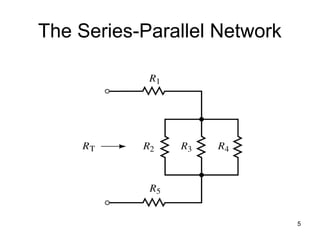
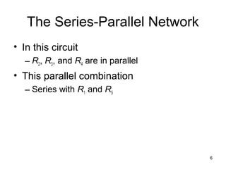
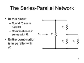
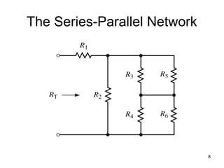
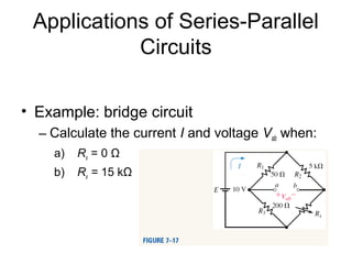
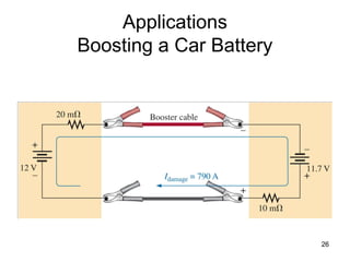
Electricity And Electronics
Fundamentals
BTE1113
Chapter 7
Series-Parallel Circuits
3
The Series-Parallel Network
• Branch
– Part of a circuit that can be simplified into
two terminals
• Components between these two
terminals
– Resistors, voltage sources, or other
elements
4
The Series-Parallel Network
• To analyze a circuit
– Identify elements in series and elements in
parallel
5
The Series-Parallel Network
6
The Series-Parallel Network
• In this circuit
– R2, R3, and R4 are in parallel
• This parallel combination
– Series with R1 and R5
7
The Series-Parallel Network
• In this circuit
– R3 and R4 are in
parallel
– Combination is in
series with R2
• Entire combination
is in parallel with
R1
8
The Series-Parallel Network
9
Analysis of Series-Parallel Circuits
• Rules for analyzing series and parallel
circuits still apply
• Same current occurs through all series
elements
10
Analysis of Series-Parallel Circuits
• Same voltage occurs across all parallel
elements
• KVL and KCL apply for all circuits
– Whether they are series, parallel, or series-
parallel
11
Analysis of Series-Parallel Circuits
• Redraw complicated circuits showing the
source at the left-hand side
• Label all nodes
12
Analysis of Series-Parallel Circuits
• Develop a strategy
– Best to begin analysis with components most
distant from the source
• Simplify recognizable combinations of
components
13
Analysis of Series-Parallel Circuits
• Determine equivalent resistance RT
• Solve for the total current
• Label polarities of voltage drops on all
components
14
Analysis of Series-Parallel Circuits
• Calculate how currents and voltages split
between elements in a circuit
• Verify your answer by taking a different
approach (when feasible)
15
Analysis of Series-Parallel Circuits
• Voltages
– Use Ohm’s Law or Voltage Divider Rule
• Currents
– Use Ohm’s Law or Current Divider Rule
16
Analysis of Series-Parallel Circuits
Applications of Series-Parallel
Circuits
• Example: bridge circuit
– Calculate the current I and voltage Vab when:
a) Rx = 0 Ω
b) Rx = 15 kΩ
Applications of Series-Parallel
Circuits (cont’d.)
• Solution
• Solution (cont’d.)
22
Potentiometers
• Example of variable resistor used as
potentiometer
– Volume control on a receiver
• Moveable terminal is at uppermost position
– Vbc = 60 V
• At the lowermost position
– Vbc = 0 V
23
Potentiometers
24
Potentiometers
• Vbc changes
– If load is connected
between b and c
– At upper position
• Vbc = 40 V
• At the lower position
– Vbc = 0 V
25
Applications
Boosting a Car Battery
26
Applications
Boosting a Car Battery
References
• Electricity and Electronics by Gerrish, Dugger
and Roberts, 10th
edition, 2009, GW Publisher
• Circuit Analysis: Theory and Practice by A. H.
Robbins, W. C. Miller, 4th
edition, 2006, Thomson
Delmar Learning
• Introductory Circuit Analysis by R. L. Boylestad,
11th
edition, 2007, Prentice Hall
27

Chap 7 bte1013

Editor's Notes

  • #8 Example 7-1 RT = R1||[R2+(R3||R4)]