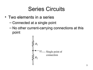
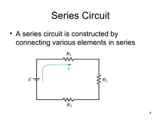
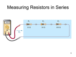
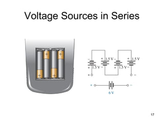
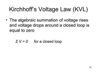
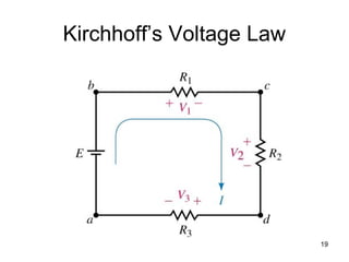
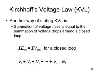
Electricity And Electronics
Fundamentals
BTE1113
Chapter 5
Series Circuits
3
Series Circuits
• Two elements in a series
– Connected at a single point
– No other current-carrying connections at this
point
4
Series Circuit
• A series circuit is constructed by
connecting various elements in series
5
Series Circuits
• Normally
– Current will leave the positive terminal of a
voltage source
– Move through the resistors
– Return to negative terminal of the source
6
Series Resistors
• The total resistance of a series
configuration is the sum of the resistance
levels.
• The more resistors we add in series, the
greater the resistance (no matter what
their value)
• The largest resistor in a series
combination will have the most impact on
the total resistance
NT RRRRRR +++++= ...4321
7
Series Resistors
8
Series Resistors
• When series resistors have the same value,
• Where N = the number of resistors in the
string
• The total series resistance is not affected by
the order in which the components are
connected.
NRRT =
9
Measuring Resistors in Series
10
Series Circuits
• The current is the same at every point in a
series circuit
• Analogy: the flow of water is the same
through each section of hose as the water
is carried to its destination
11
Power in a Series Circuit
• Power dissipated by each resistor is
determined by the power formulas:
P = VI = V2
/R = I2
R
• Maximum power is delivered to the
largest resistor
12
Power in a Series Circuit
• Since energy must be conserved, power
delivered by voltage source is equal to
total power dissipated by resistors
PT = P1 + P2 + P3 + ∙∙∙ + Pn
13
Voltage Sources in Series
• In a circuit with more than one source in
series
– Sources can be replaced by a single source
having a value that is the sum or difference
of the individual sources
• Polarities must be taken into account
14
Voltage Sources in Series
• Resultant source
– Sum of the rises in one direction minus the
sum of the voltages in the opposite direction
15
Voltage Sources in Series
16
Voltage Sources in Series
17
Voltage Sources in Series
18
Kirchhoff’s Voltage Law (KVL)
• The algebraic summation of voltage rises
and voltage drops around a closed loop is
equal to zero
Σ V = 0 for a closed loop
19
Kirchhoff’s Voltage Law
20
Kirchhoff’s Voltage Law (KVL)
• Another way of stating KVL is:
– Summation of voltage rises is equal to the
summation of voltage drops around a closed
loop
ΣErises = ΣVdrops for a closed loop
V1 + V2 + V3 + ∙∙∙ + Vn = ET
21
The Voltage Divider Rule
• Voltage applied to a series circuit
– Will be dropped across all the resistors in
proportion to the magnitude of the individual
resistors
22
The Voltage Divider Rule
• Voltage across a resistor in a series
circuit is equal to the total applied voltage
times value of that resistor divided by the
total resistance of the series circuit
T
x
x
R
R
EV =
23
Voltage Divider Rule
Application
• If a single resistor is very large compared
to the other series resistors, the voltage
across that resistor will be the source
voltage
• If the resistor is very small, the voltage
across it will be essentially zero
24
Voltage Divider Rule Application
• If a resistor is more than 100 times larger
than another resistor
– Smaller resistor can be neglected
25
Circuit Ground
• Ground
– Point of reference or a common point in a
circuit for making measurements
• One type of grounding is chassis ground
• In this type of grounding
– Common point of circuit is often the metal
chassis of the piece of equipment
26
Circuit Ground
• Chassis ground
– Often connected to Earth Ground
• Earth ground
– Physically connected to the earth by a metal
pipe or rod
27
Circuit Ground
28
Circuit Ground
• If a fault occurs within a circuit, the current
is redirected to the earth
• Voltages are often measured with respect
to ground
29
Double Subscripts
30
Double Subscripts
• For the circuit shown, we can express the
voltage between any two node points (a
and b) as Vab.
• If a is at a higher potential than b, then Vab
is positive
31
Double Subscripts
• If b is at a higher potential than a, then Vab
is negative
• In this case, Vab would be negative
32
Single Subscripts
• In a circuit with a ground reference point
– Voltages may be expressed with respect to
that reference point
• Va
– Voltage at point a with respect to ground
– Ground represents a point of zero reference
potential
33
Single Subscripts
• Any voltage with a single subscript is with
respect to ground
34
Single Subscripts
• If voltages at various
points in a circuit are
known with respect to
ground, then the
voltage between
points is easily
determined
• Vab = Va – Vb
35
Applications
 Holiday lights
 Holiday lights are connected in series if one
wire enters and leaves the casing.
 If one of the filaments burns out or is broken,
all of the lights go out unless a fuse link is
used.
 A fuse link is a soft conducting metal with a
coating on it that breaks down if the bulb burn out,
causing the bulb to be by-passed, thus only one
bulb goes out.
36
Applications
 Microwave oven
 A series circuit can be very useful in the
design of safety equipment.
 In a microwave, it is very dangerous if the
oven door is not closed or sealed properly.
Microwaves use a series circuit with
magnetic switches on the door to ensure
that the door is properly closed.
 Magnetic switches are switches where the
magnet draws a magnetic conducting bar
between two conductors to complete the
circuit.
37
Applications
References
• Electricity and Electronics by Gerrish, Dugger
and Roberts, 10th
edition, 2009, GW Publisher
• Circuit Analysis: Theory and Practice by A. H.
Robbins, W. C. Miller, 4th
edition, 2006, Thomson
Delmar Learning
• Introductory Circuit Analysis by R. L. Boylestad,
11th
edition, 2007, Prentice Hall
38

Chap 5 bte1013

  • 1.
  • 2.
  • 3.
    3 Series Circuits • Twoelements in a series – Connected at a single point – No other current-carrying connections at this point
  • 4.
    4 Series Circuit • Aseries circuit is constructed by connecting various elements in series
  • 5.
    5 Series Circuits • Normally –Current will leave the positive terminal of a voltage source – Move through the resistors – Return to negative terminal of the source
  • 6.
    6 Series Resistors • Thetotal resistance of a series configuration is the sum of the resistance levels. • The more resistors we add in series, the greater the resistance (no matter what their value) • The largest resistor in a series combination will have the most impact on the total resistance NT RRRRRR +++++= ...4321
  • 7.
  • 8.
    8 Series Resistors • Whenseries resistors have the same value, • Where N = the number of resistors in the string • The total series resistance is not affected by the order in which the components are connected. NRRT =
  • 9.
  • 10.
    10 Series Circuits • Thecurrent is the same at every point in a series circuit • Analogy: the flow of water is the same through each section of hose as the water is carried to its destination
  • 11.
    11 Power in aSeries Circuit • Power dissipated by each resistor is determined by the power formulas: P = VI = V2 /R = I2 R • Maximum power is delivered to the largest resistor
  • 12.
    12 Power in aSeries Circuit • Since energy must be conserved, power delivered by voltage source is equal to total power dissipated by resistors PT = P1 + P2 + P3 + ∙∙∙ + Pn
  • 13.
    13 Voltage Sources inSeries • In a circuit with more than one source in series – Sources can be replaced by a single source having a value that is the sum or difference of the individual sources • Polarities must be taken into account
  • 14.
    14 Voltage Sources inSeries • Resultant source – Sum of the rises in one direction minus the sum of the voltages in the opposite direction
  • 15.
  • 16.
  • 17.
  • 18.
    18 Kirchhoff’s Voltage Law(KVL) • The algebraic summation of voltage rises and voltage drops around a closed loop is equal to zero Σ V = 0 for a closed loop
  • 19.
  • 20.
    20 Kirchhoff’s Voltage Law(KVL) • Another way of stating KVL is: – Summation of voltage rises is equal to the summation of voltage drops around a closed loop ΣErises = ΣVdrops for a closed loop V1 + V2 + V3 + ∙∙∙ + Vn = ET
  • 21.
    21 The Voltage DividerRule • Voltage applied to a series circuit – Will be dropped across all the resistors in proportion to the magnitude of the individual resistors
  • 22.
    22 The Voltage DividerRule • Voltage across a resistor in a series circuit is equal to the total applied voltage times value of that resistor divided by the total resistance of the series circuit T x x R R EV =
  • 23.
    23 Voltage Divider Rule Application •If a single resistor is very large compared to the other series resistors, the voltage across that resistor will be the source voltage • If the resistor is very small, the voltage across it will be essentially zero
  • 24.
    24 Voltage Divider RuleApplication • If a resistor is more than 100 times larger than another resistor – Smaller resistor can be neglected
  • 25.
    25 Circuit Ground • Ground –Point of reference or a common point in a circuit for making measurements • One type of grounding is chassis ground • In this type of grounding – Common point of circuit is often the metal chassis of the piece of equipment
  • 26.
    26 Circuit Ground • Chassisground – Often connected to Earth Ground • Earth ground – Physically connected to the earth by a metal pipe or rod
  • 27.
  • 28.
    28 Circuit Ground • Ifa fault occurs within a circuit, the current is redirected to the earth • Voltages are often measured with respect to ground
  • 29.
  • 30.
    30 Double Subscripts • Forthe circuit shown, we can express the voltage between any two node points (a and b) as Vab. • If a is at a higher potential than b, then Vab is positive
  • 31.
    31 Double Subscripts • Ifb is at a higher potential than a, then Vab is negative • In this case, Vab would be negative
  • 32.
    32 Single Subscripts • Ina circuit with a ground reference point – Voltages may be expressed with respect to that reference point • Va – Voltage at point a with respect to ground – Ground represents a point of zero reference potential
  • 33.
    33 Single Subscripts • Anyvoltage with a single subscript is with respect to ground
  • 34.
    34 Single Subscripts • Ifvoltages at various points in a circuit are known with respect to ground, then the voltage between points is easily determined • Vab = Va – Vb
  • 35.
    35 Applications  Holiday lights Holiday lights are connected in series if one wire enters and leaves the casing.  If one of the filaments burns out or is broken, all of the lights go out unless a fuse link is used.  A fuse link is a soft conducting metal with a coating on it that breaks down if the bulb burn out, causing the bulb to be by-passed, thus only one bulb goes out.
  • 36.
    36 Applications  Microwave oven A series circuit can be very useful in the design of safety equipment.  In a microwave, it is very dangerous if the oven door is not closed or sealed properly. Microwaves use a series circuit with magnetic switches on the door to ensure that the door is properly closed.  Magnetic switches are switches where the magnet draws a magnetic conducting bar between two conductors to complete the circuit.
  • 37.
  • 38.
    References • Electricity andElectronics by Gerrish, Dugger and Roberts, 10th edition, 2009, GW Publisher • Circuit Analysis: Theory and Practice by A. H. Robbins, W. C. Miller, 4th edition, 2006, Thomson Delmar Learning • Introductory Circuit Analysis by R. L. Boylestad, 11th edition, 2007, Prentice Hall 38