The document discusses various aspects of fuel injection systems, including:
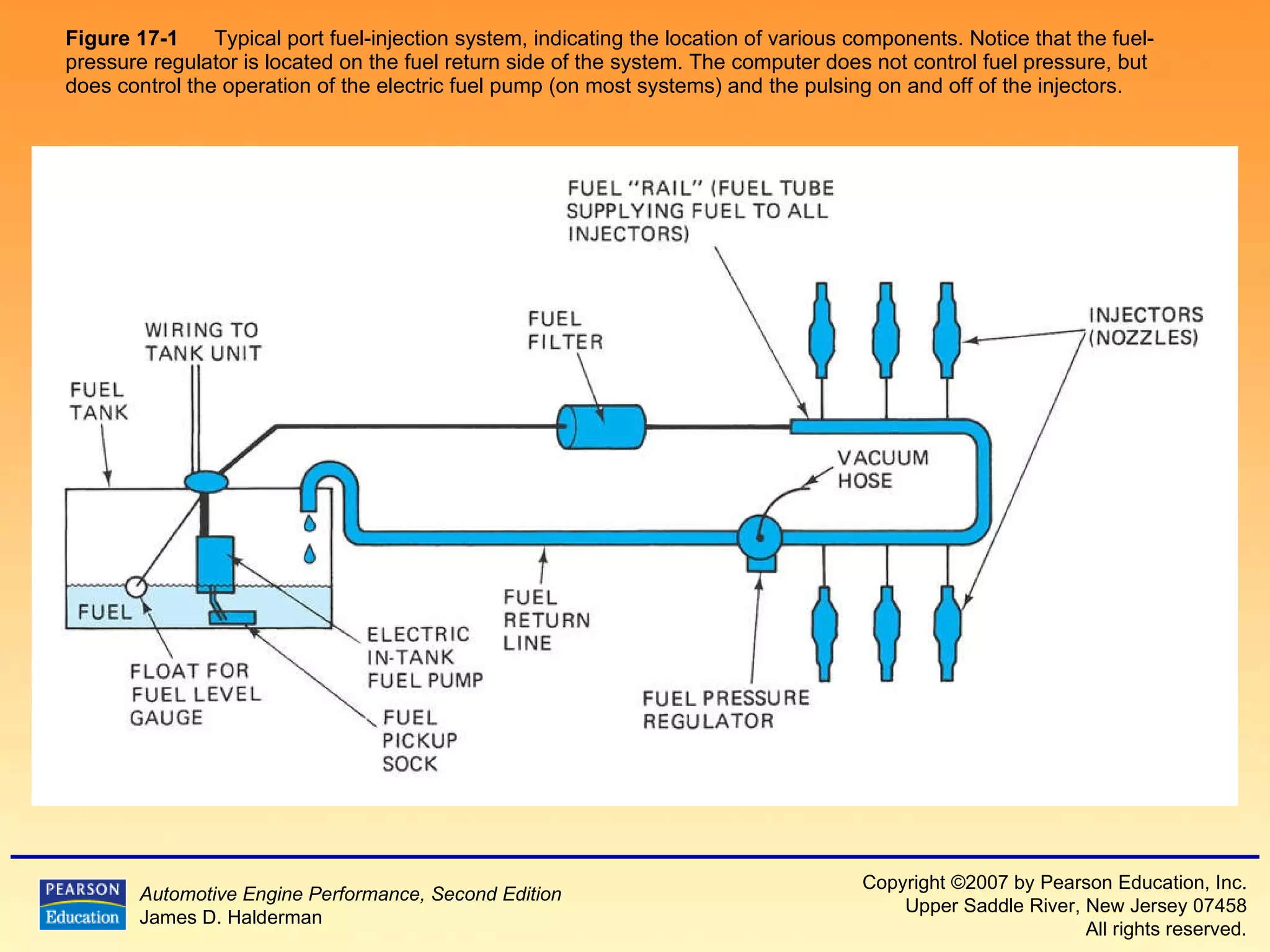
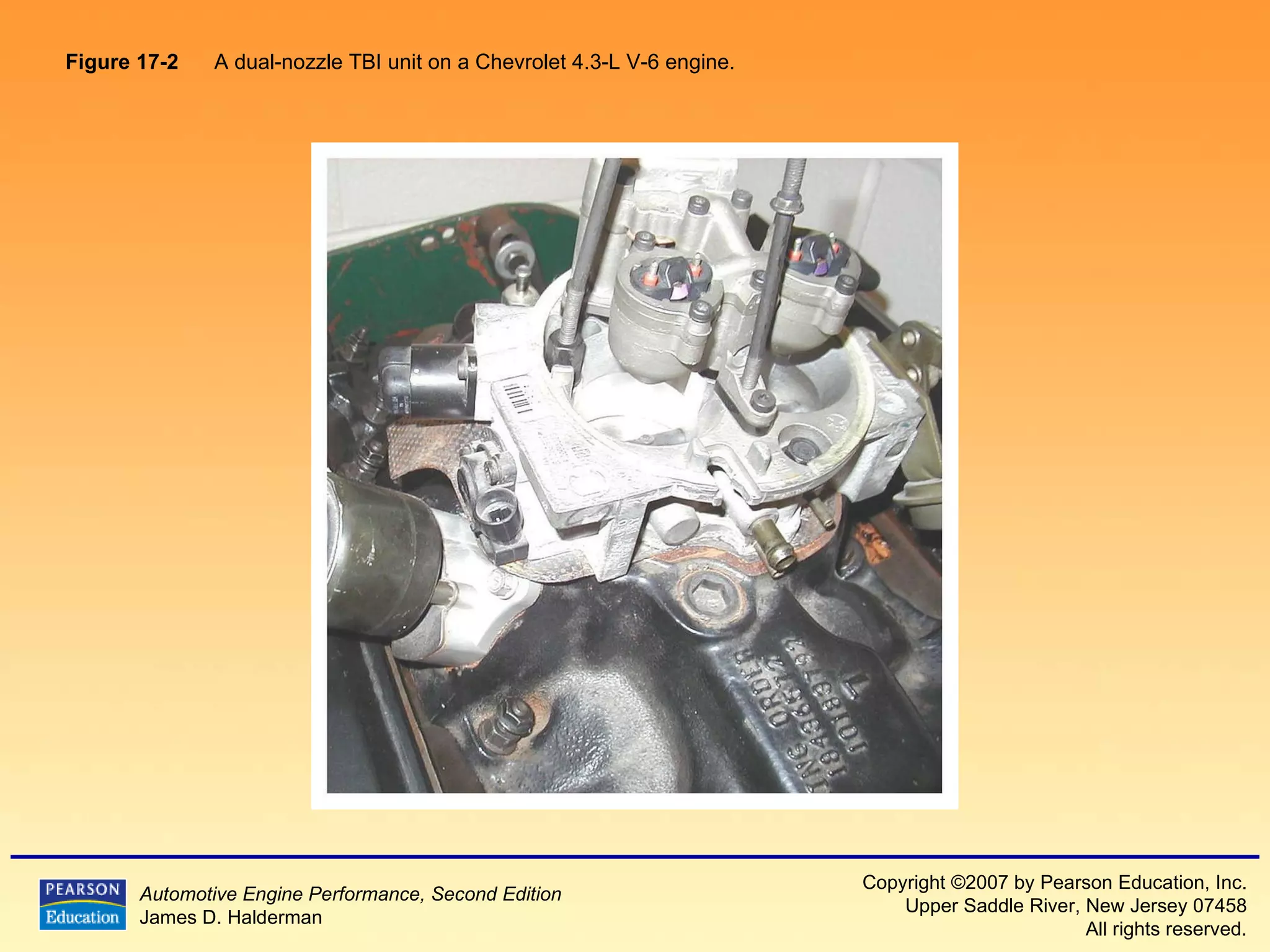
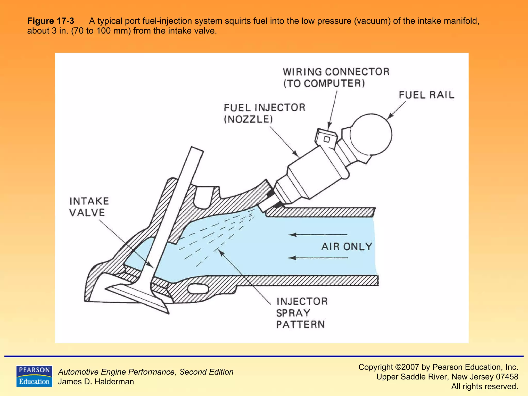
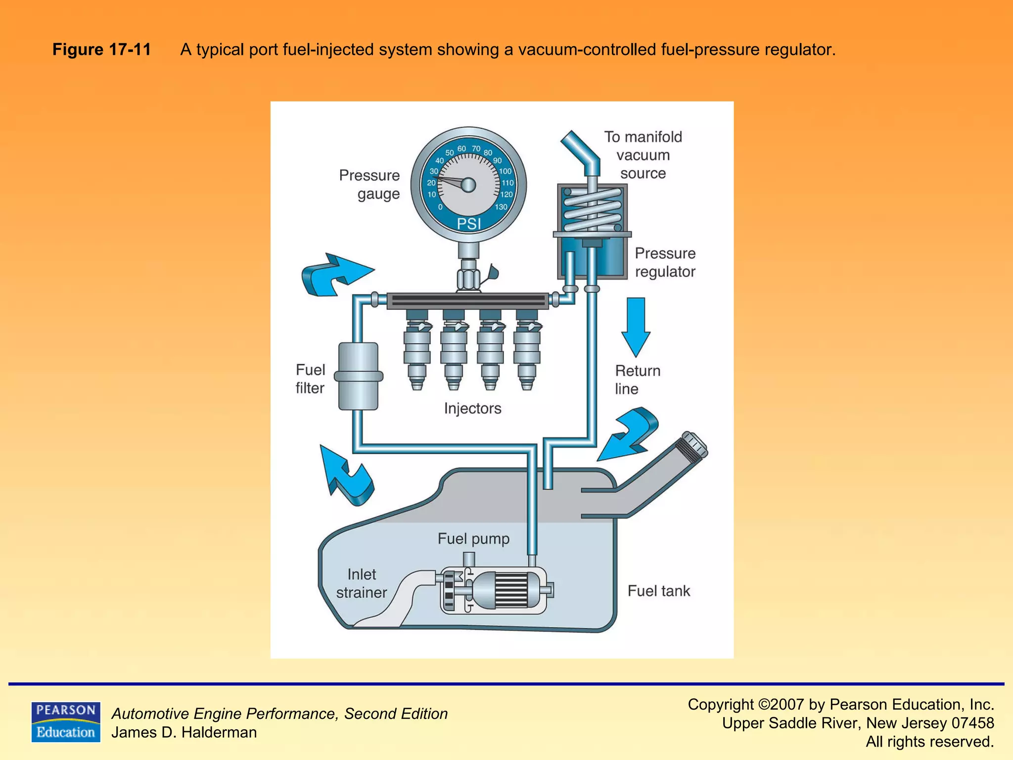
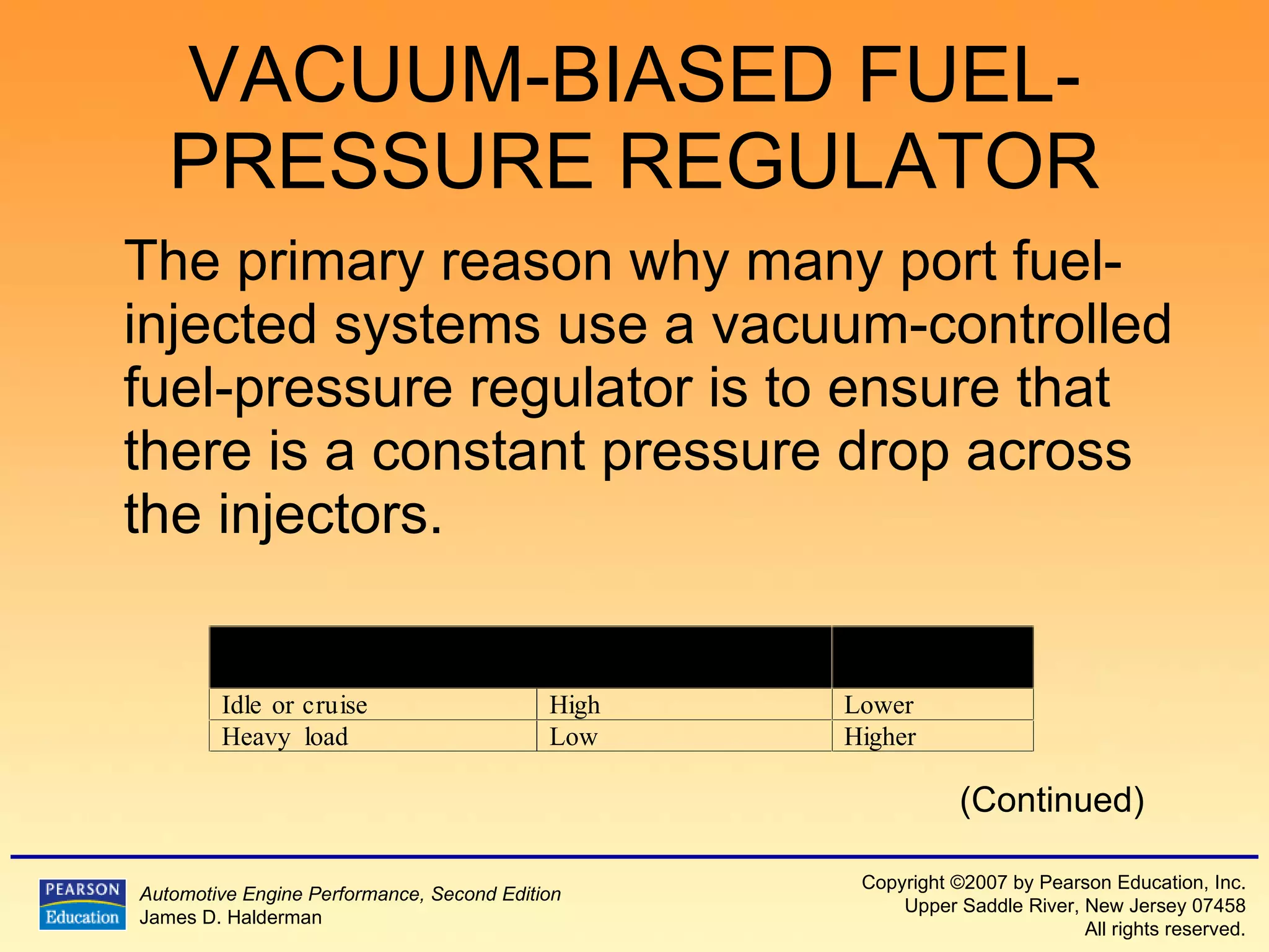
1) It describes the basic components and operation of port fuel injection and throttle body injection systems, including the fuel pump, fuel pressure regulator, injectors, and how they are controlled by the computer.
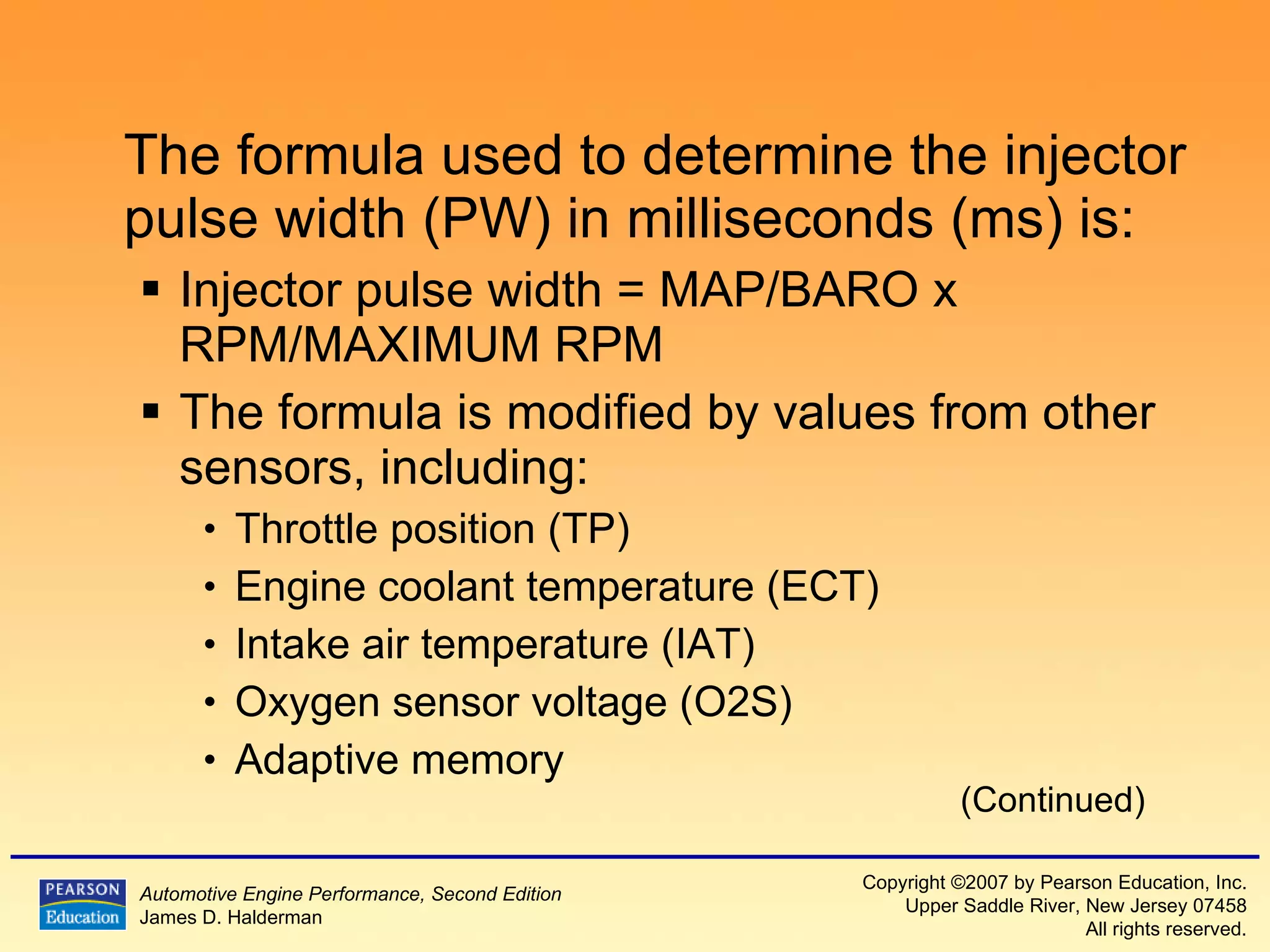
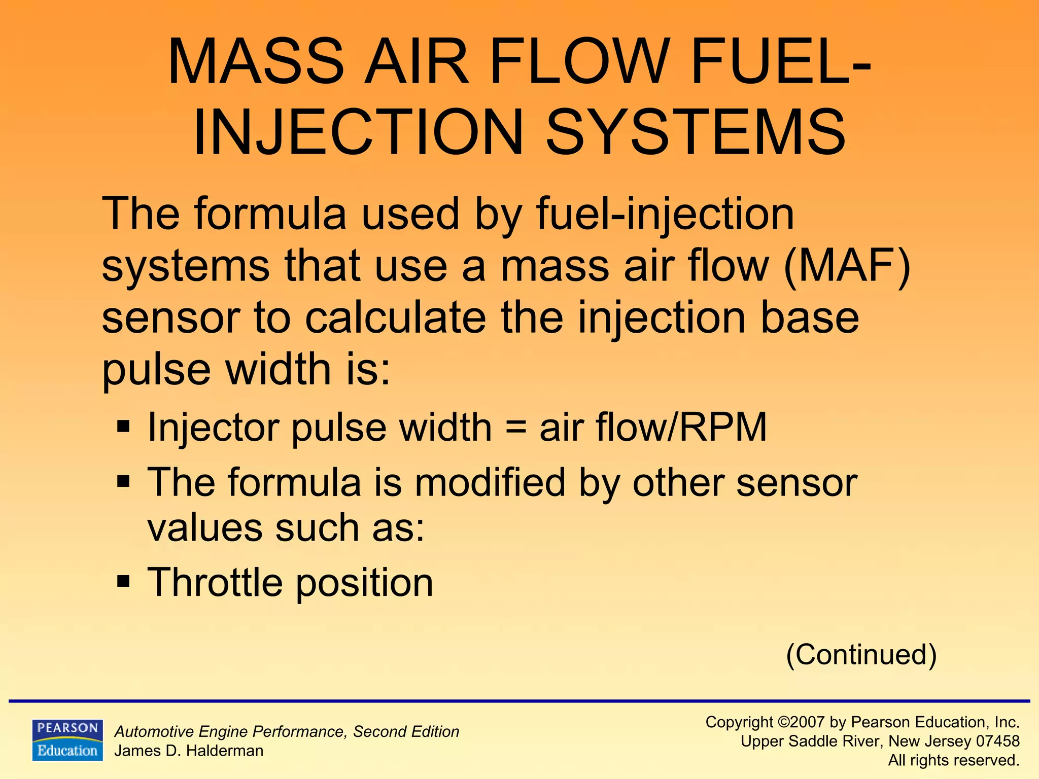
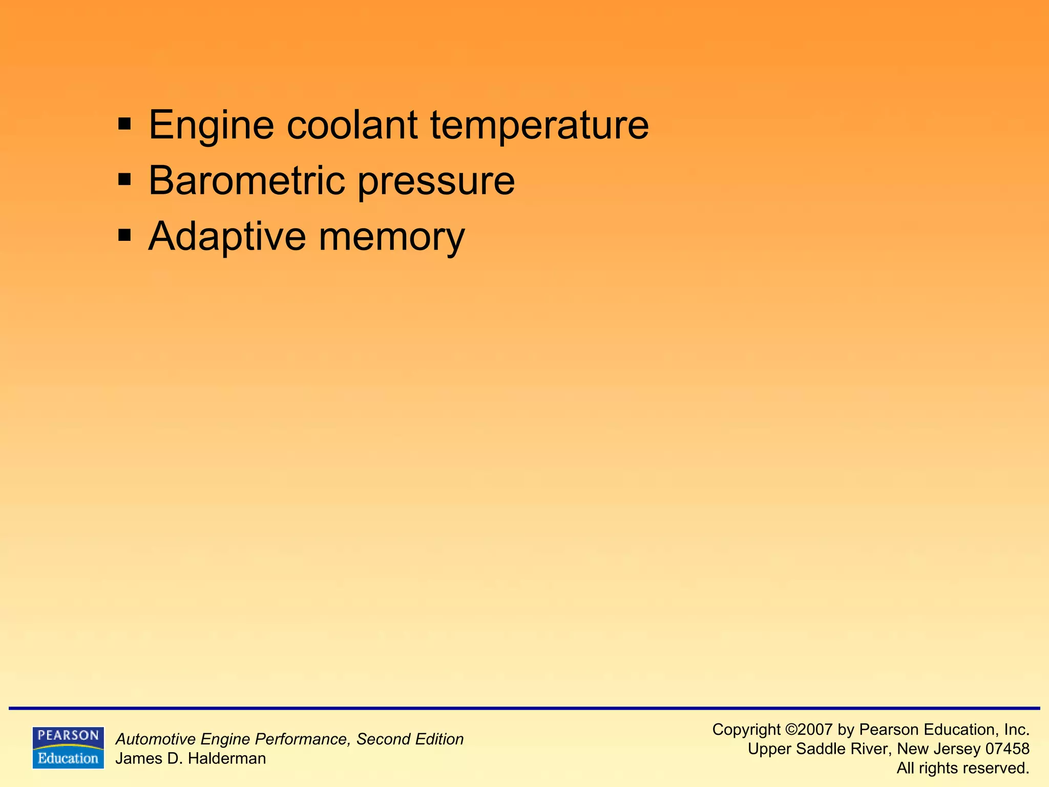
2) It explains the different types of fuel injection systems and how they determine the proper fuel amount, such as speed density and mass air flow systems.
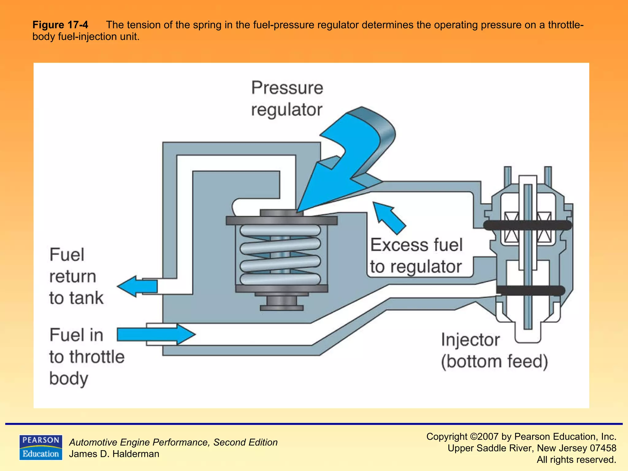
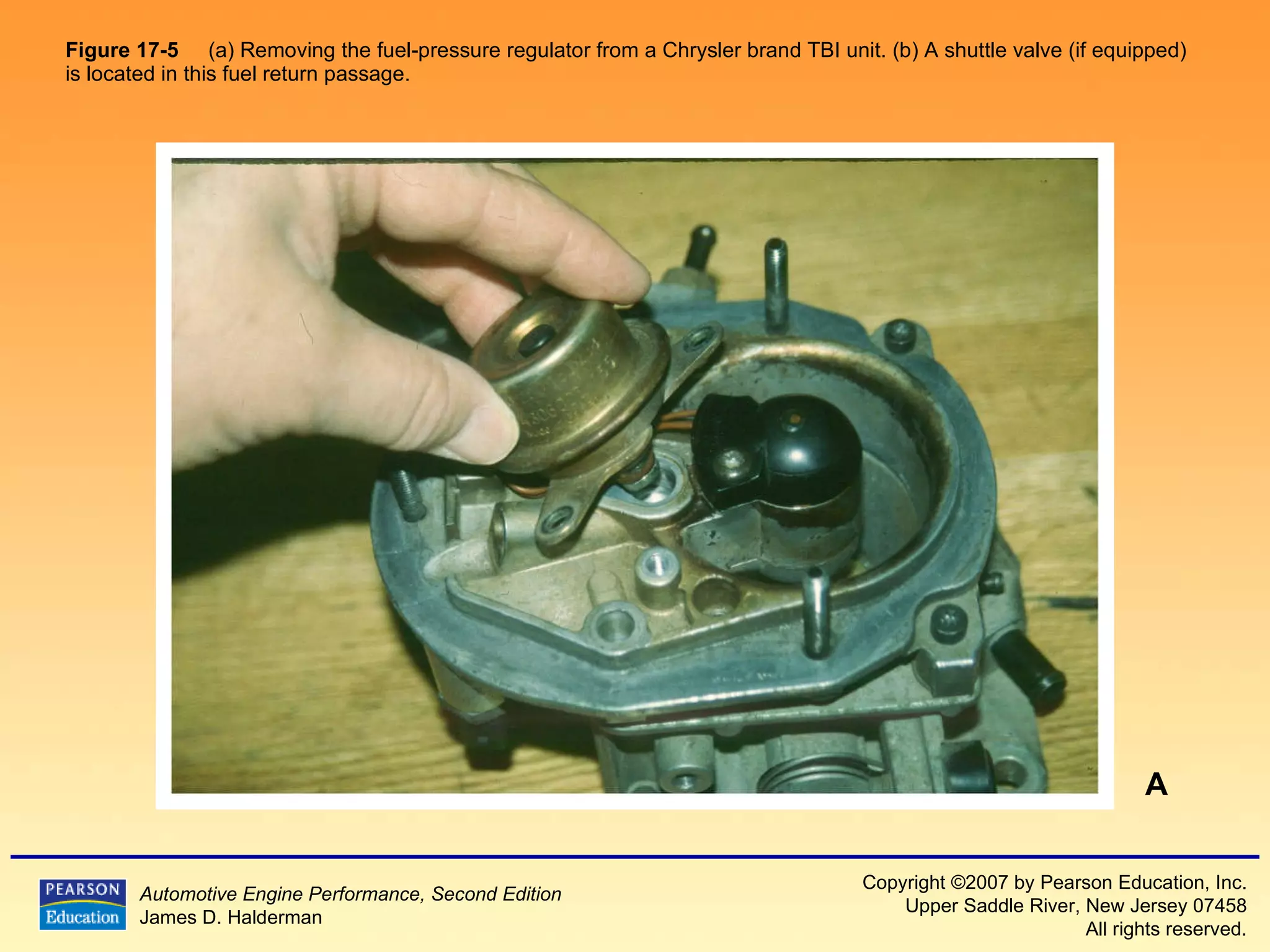
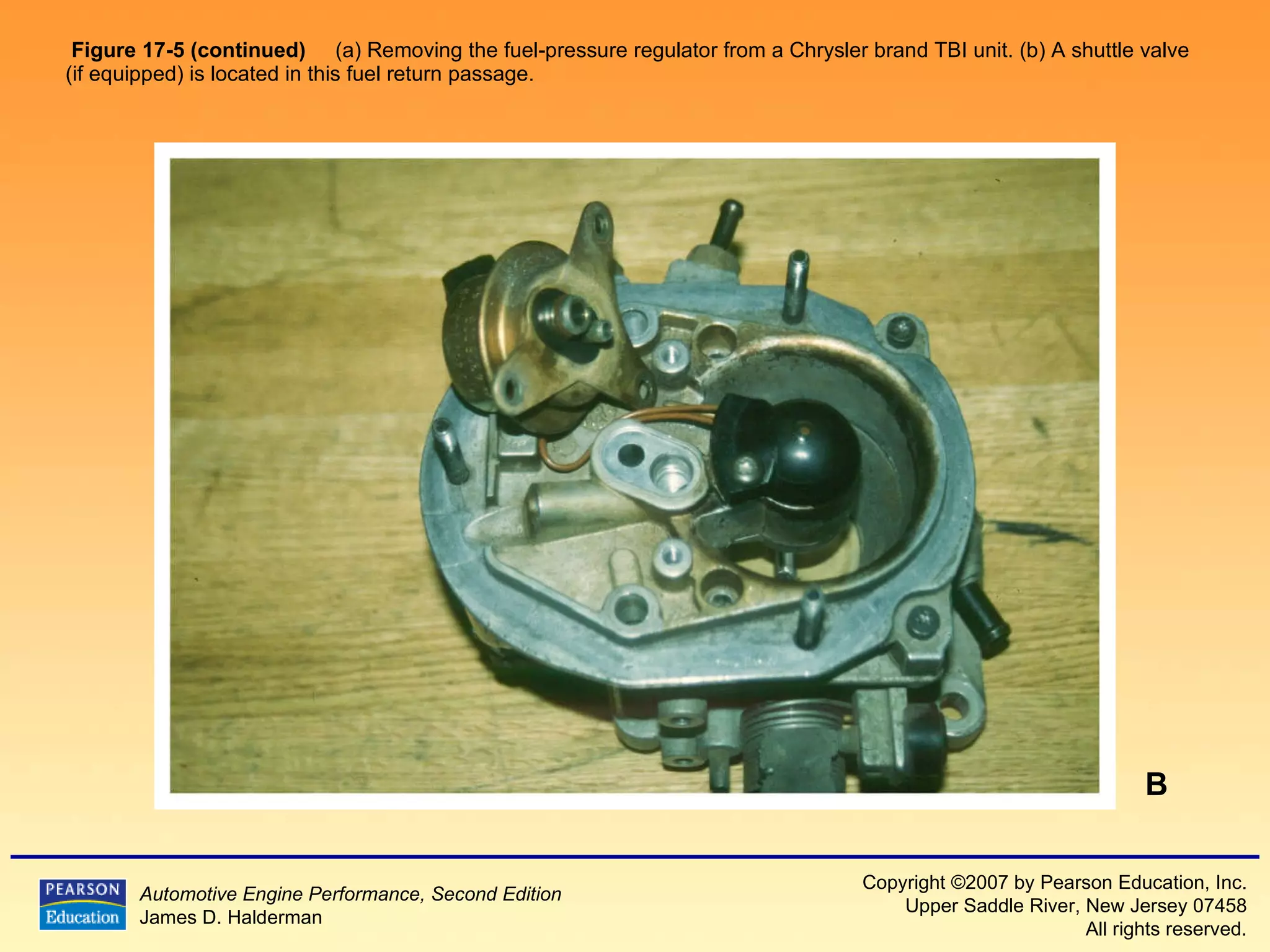
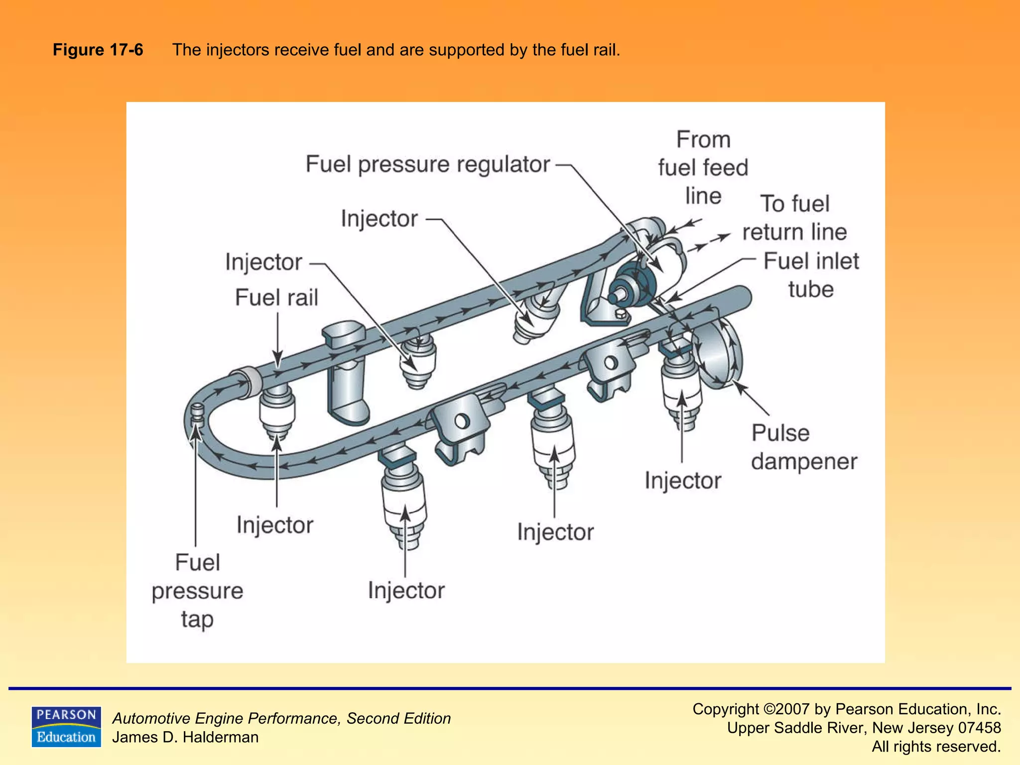
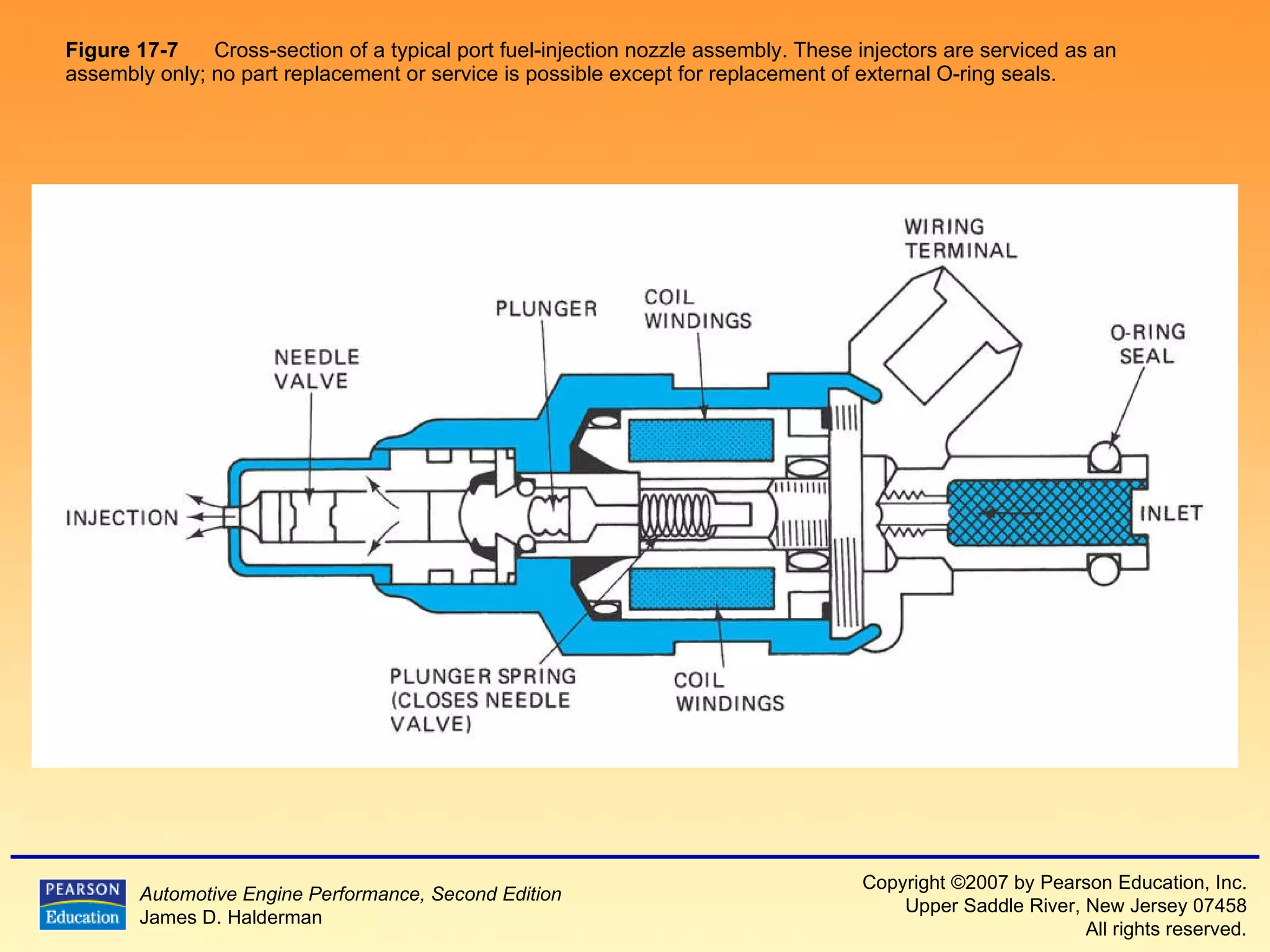
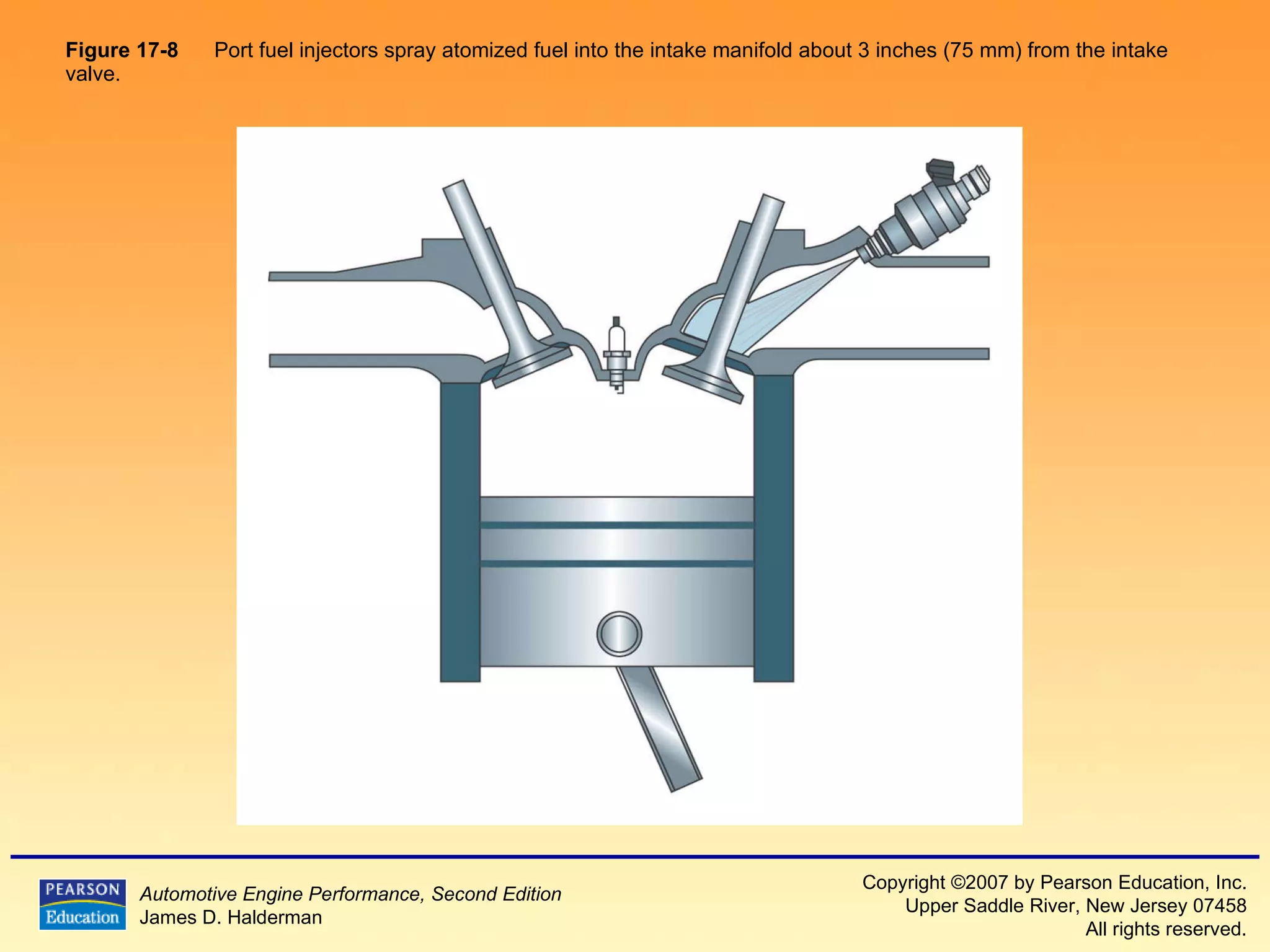
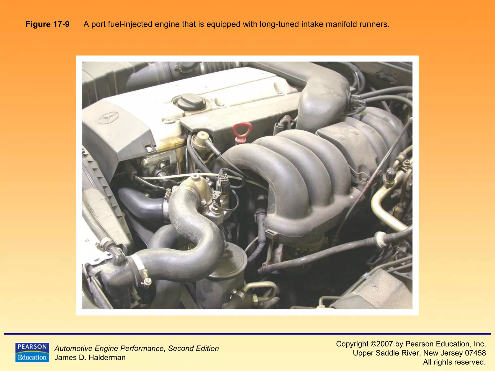
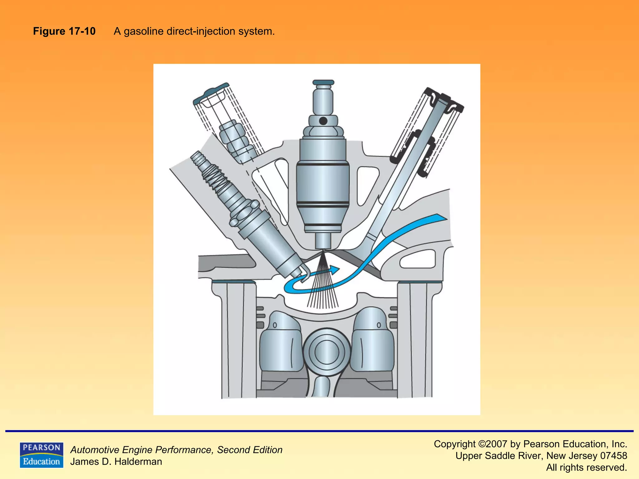
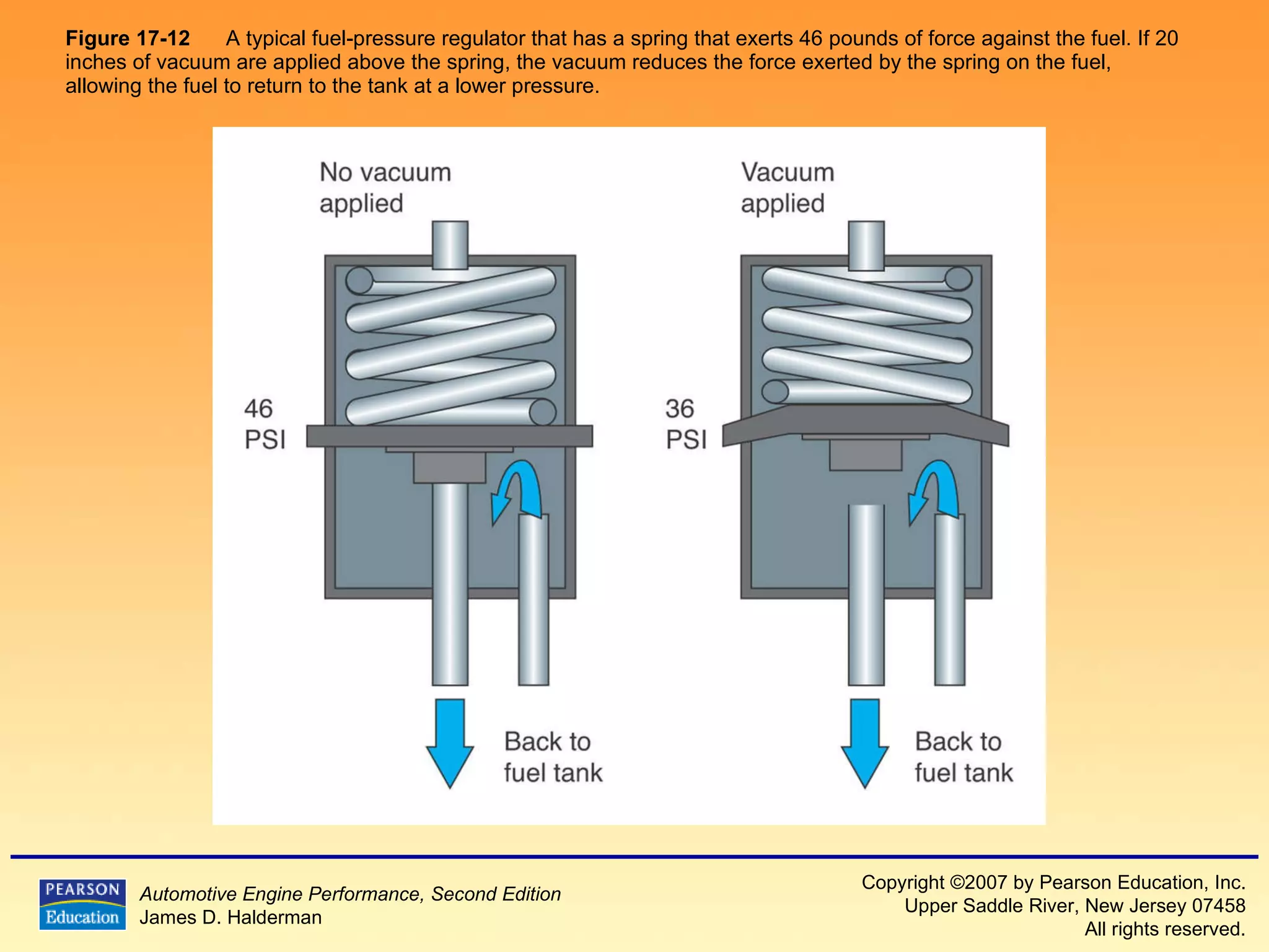
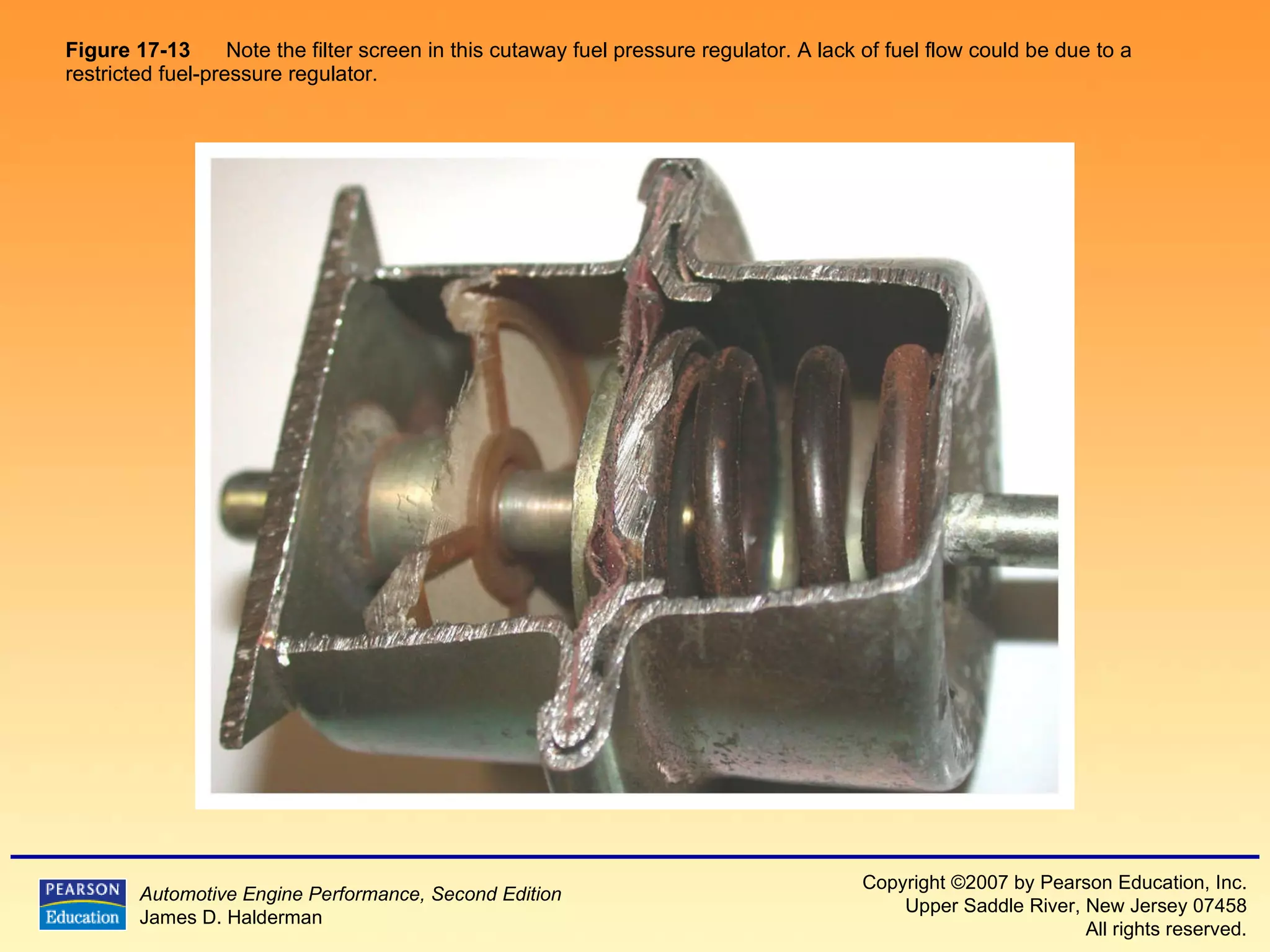
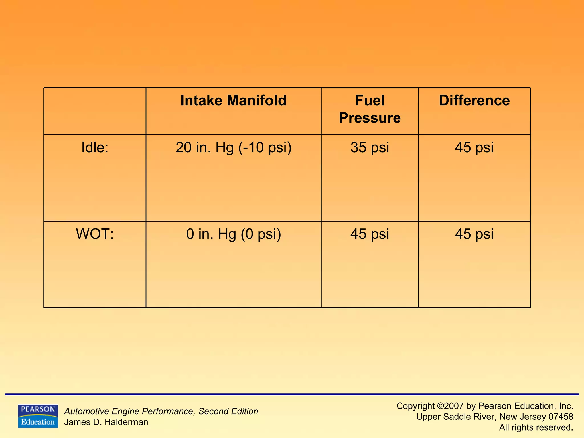
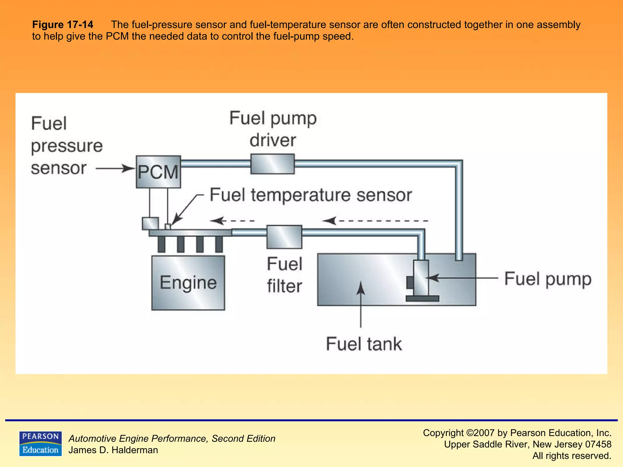
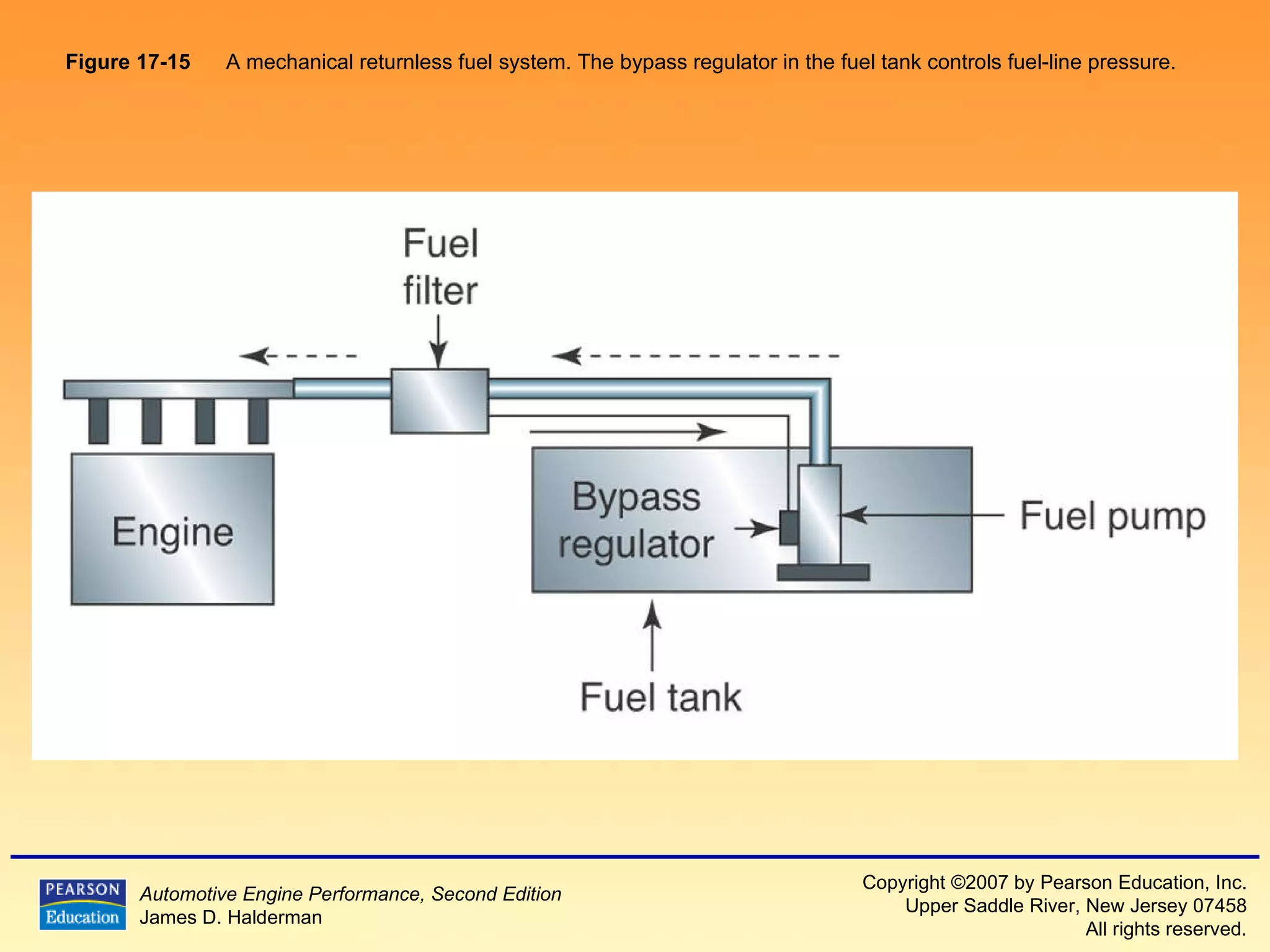
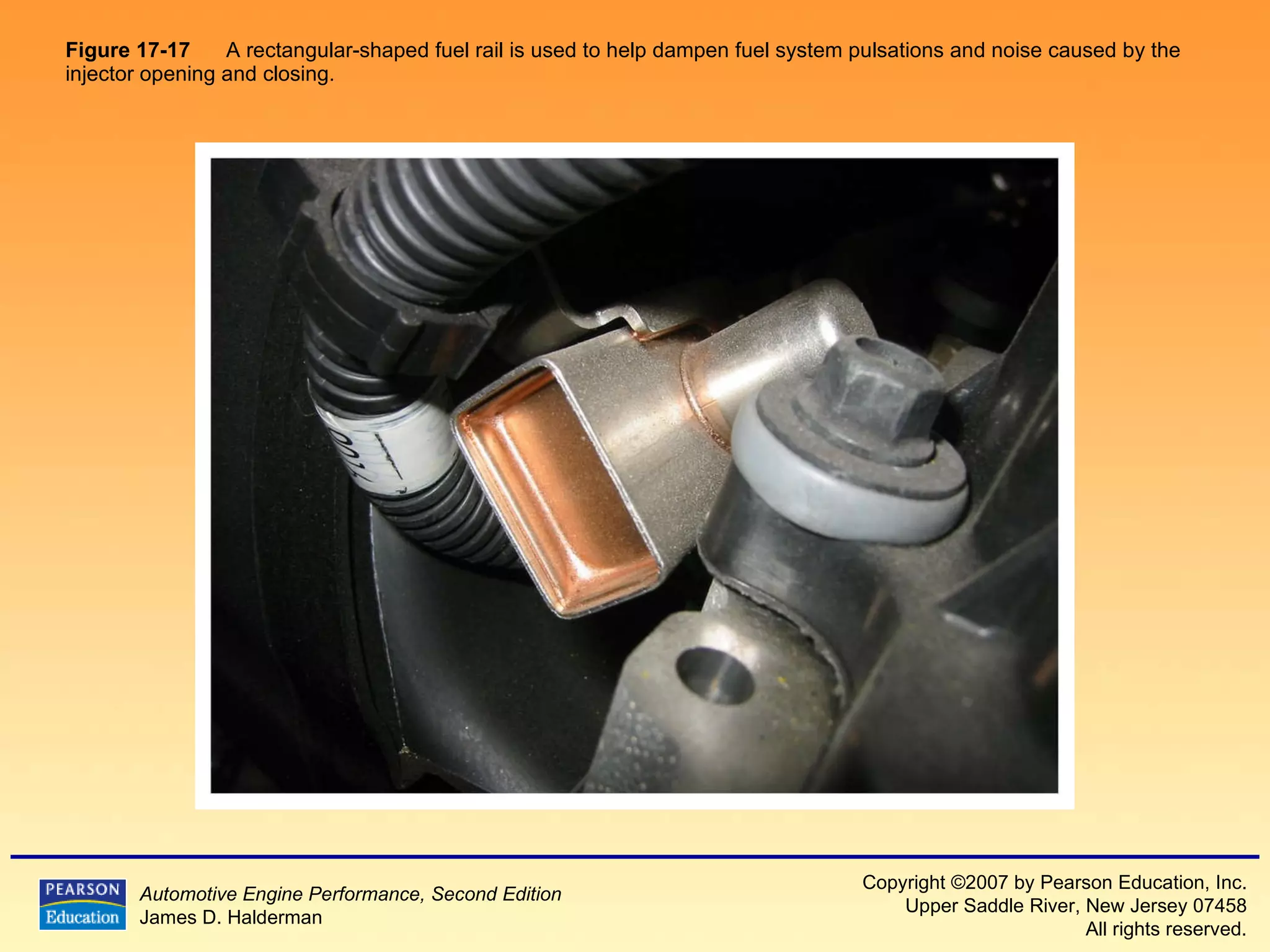
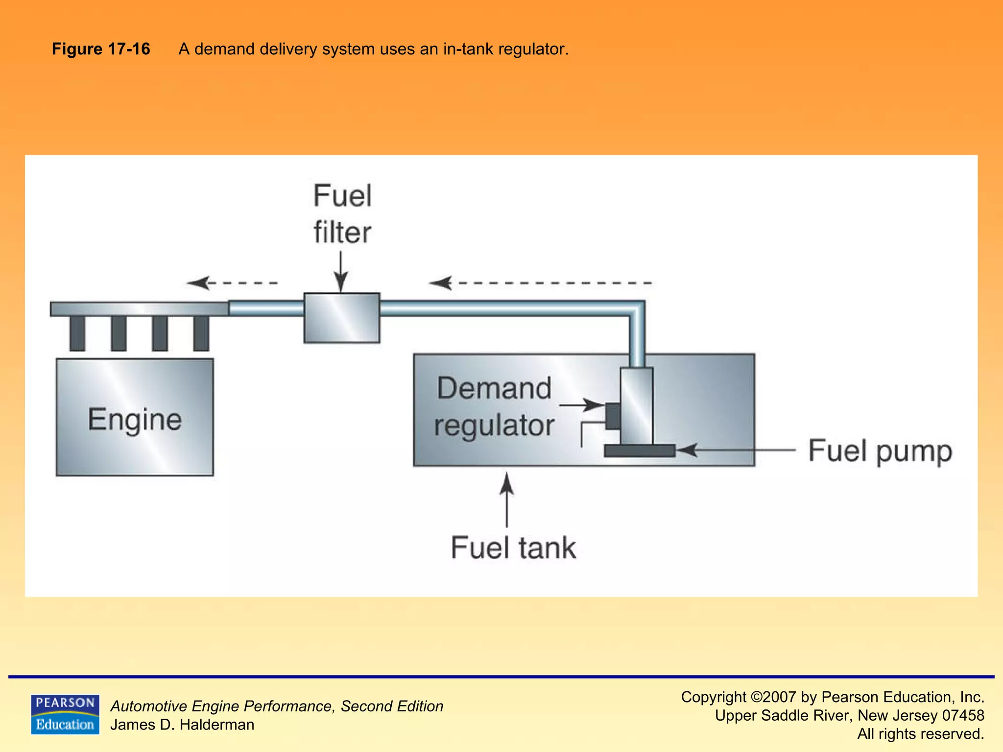
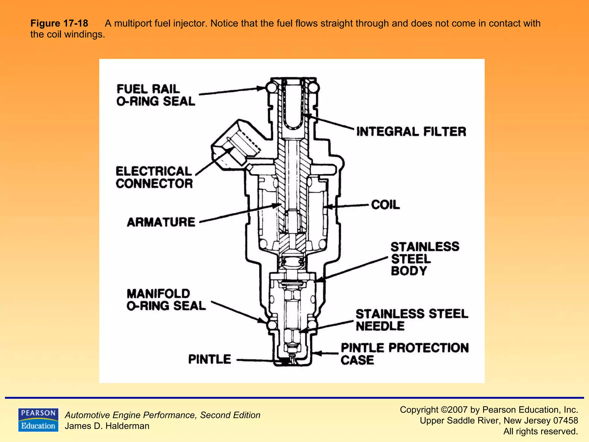
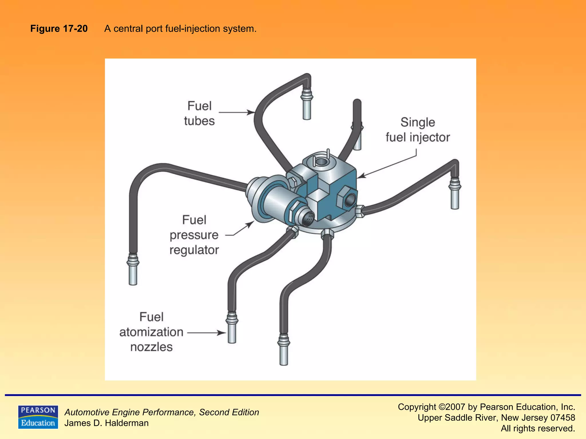
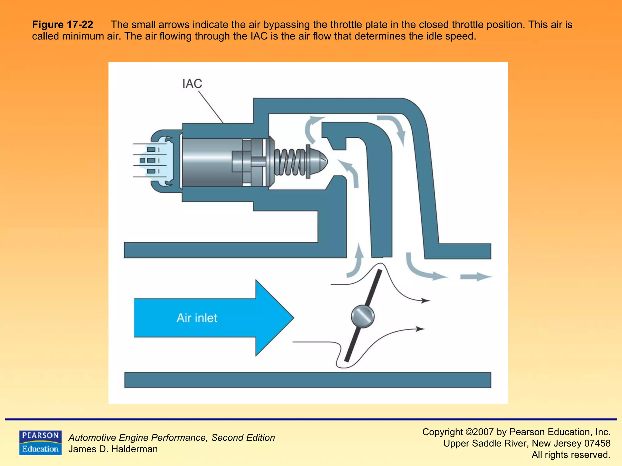
3) It provides diagrams and descriptions of the main components like the fuel rail, injectors, and pressure regulator and how they function within the fuel injection system.
11. Figure 17-1 Typical port fuel-injection system, indicating the location of various components. Notice that the fuel-pressure regulator is located on the fuel return side of the system. The computer does not control fuel pressure, but does control the operation of the electric fuel pump (on most systems) and the pulsing on and off of the injectors.
12. Figure 17-2 A dual-nozzle TBI unit on a Chevrolet 4.3-L V-6 engine.
13. Figure 17-3 A typical port fuel-injection system squirts fuel into the low pressure (vacuum) of the intake manifold, about 3 in. (70 to 100 mm) from the intake valve.
14.
15.
16.
17.
18. Figure 17-4 The tension of the spring in the fuel-pressure regulator determines the operating pressure on a throttle-body fuel-injection unit.
19. Figure 17-5 (a) Removing the fuel-pressure regulator from a Chrysler brand TBI unit. (b) A shuttle valve (if equipped) is located in this fuel return passage. A
20. Figure 17-5 (continued) (a) Removing the fuel-pressure regulator from a Chrysler brand TBI unit. (b) A shuttle valve (if equipped) is located in this fuel return passage. B
21.
22.
23.
24.
25.
26.
27.
28.
29.
30. Figure 17-6 The injectors receive fuel and are supported by the fuel rail.
31. Figure 17-7 Cross-section of a typical port fuel-injection nozzle assembly. These injectors are serviced as an assembly only; no part replacement or service is possible except for replacement of external O-ring seals.
32. Figure 17-8 Port fuel injectors spray atomized fuel into the intake manifold about 3 inches (75 mm) from the intake valve.
33. Figure 17-9 A port fuel-injected engine that is equipped with long-tuned intake manifold runners.
34.
35.
36. Figure 17-10 A gasoline direct-injection system.
37.
38.
39.
40. Figure 17-11 A typical port fuel-injected system showing a vacuum-controlled fuel-pressure regulator.
41. Figure 17-12 A typical fuel-pressure regulator that has a spring that exerts 46 pounds of force against the fuel. If 20 inches of vacuum are applied above the spring, the vacuum reduces the force exerted by the spring on the fuel, allowing the fuel to return to the tank at a lower pressure.
42. Figure 17-13 Note the filter screen in this cutaway fuel pressure regulator. A lack of fuel flow could be due to a restricted fuel-pressure regulator.
47. Figure 17-14 The fuel-pressure sensor and fuel-temperature sensor are often constructed together in one assembly to help give the PCM the needed data to control the fuel-pump speed.
48.
49. Figure 17-15 A mechanical returnless fuel system. The bypass regulator in the fuel tank controls fuel-line pressure.
50.
51.
52.
53.
54. Figure 17-17 A rectangular-shaped fuel rail is used to help dampen fuel system pulsations and noise caused by the injector opening and closing.
55. Figure 17-16 A demand delivery system uses an in-tank regulator.
56.
57. Figure 17-18 A multiport fuel injector. Notice that the fuel flows straight through and does not come in contact with the coil windings.
58. Figure 17-19 Each of the eight injectors shown are producing a correct spray pattern for the applications. While all throttle-body injectors spray a conical pattern, most port fuel-injectors do not.
59.
60.
61. Figure 17-20 A central port fuel-injection system.
62. Figure 17-21 A view of a sequential central fuel-injection unit showing the electrical connections for the six individual solenoids.
63.
64.
65.
66.
67.
68.
69.
70. Figure 17-22 The small arrows indicate the air bypassing the throttle plate in the closed throttle position. This air is called minimum air. The air flowing through the IAC is the air flow that determines the idle speed.
71.
72.
73.
74. Figure 17-23 Most stepper motors use four wires, which are pulsed by the computer to rotate the armature in steps.
75.
76. Figure 17-24 Not all fuel injectors create a hollow cone discharge because the pattern depends on the design.