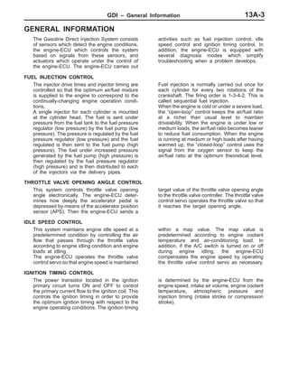
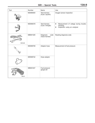
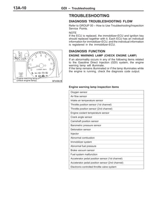
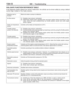
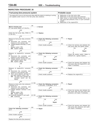
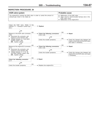
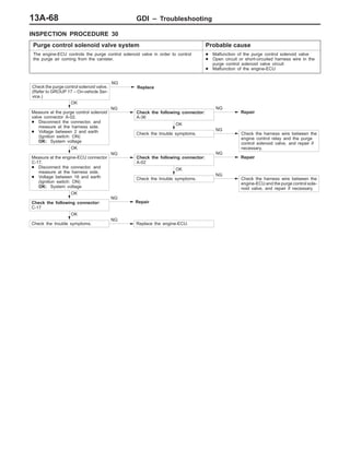
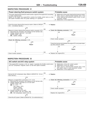
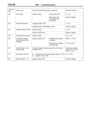
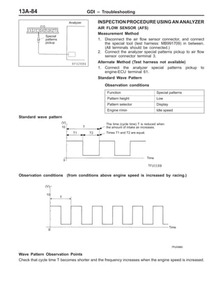
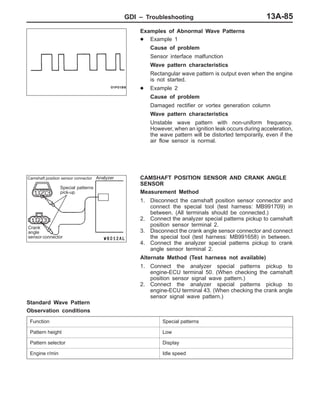
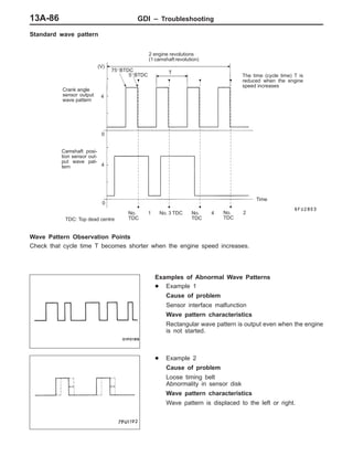
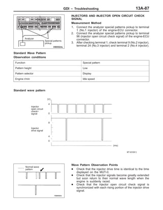
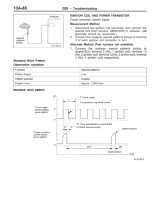
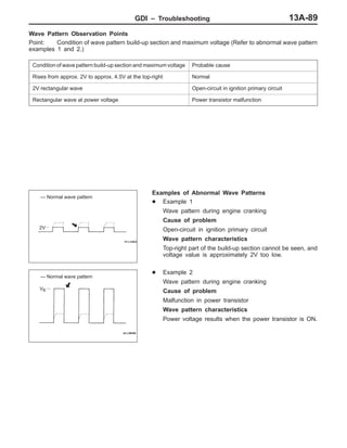
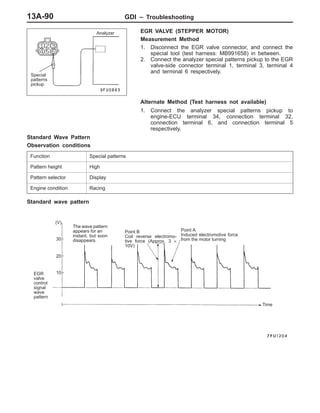
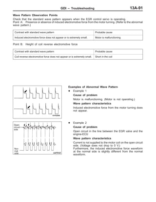
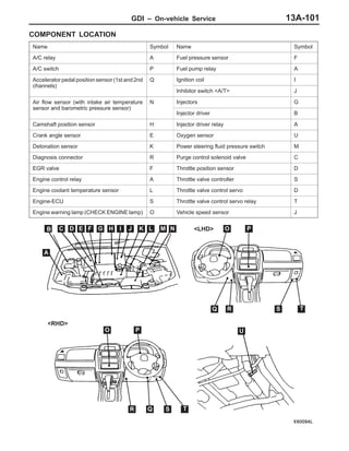
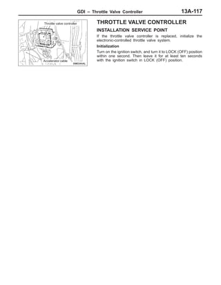
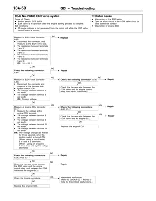
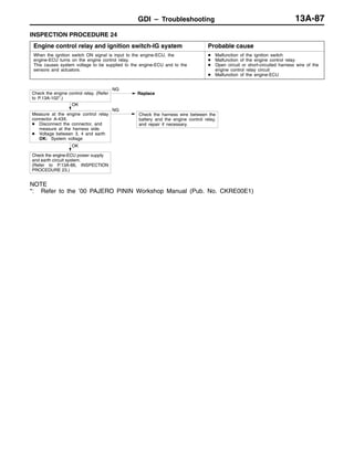
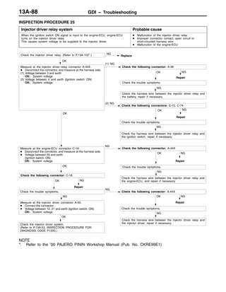
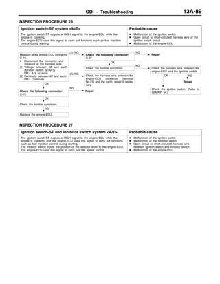
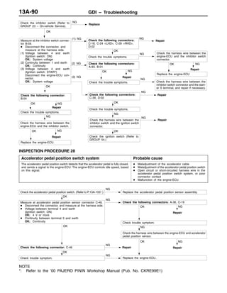
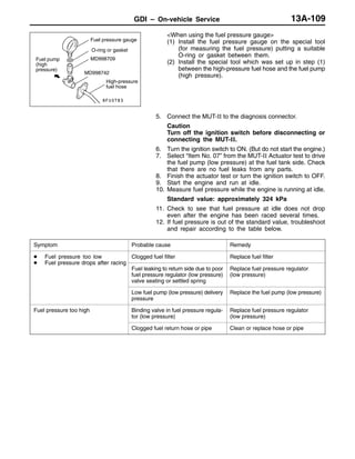
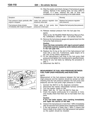
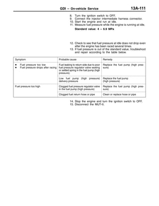
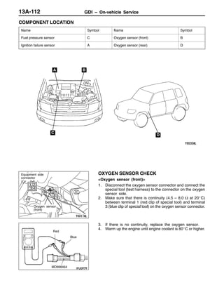
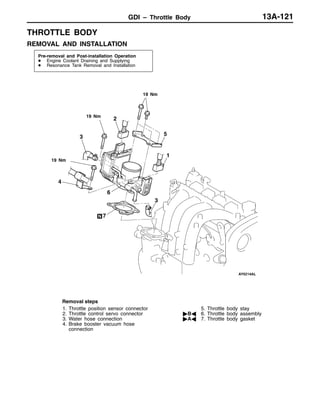
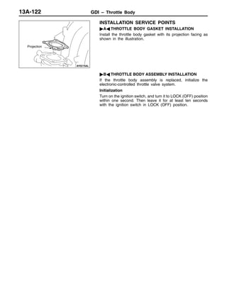
The document discusses the gasoline direct injection (GDI) system. It describes the main components of the system including sensors that detect engine conditions, an engine control unit that controls the system based on sensor signals, and actuators that operate under ECU control. The ECU performs functions like fuel injection control, idle speed control, and ignition timing control. It also has self-diagnosis capabilities to assist with troubleshooting.
![GDI – General Information13A-6
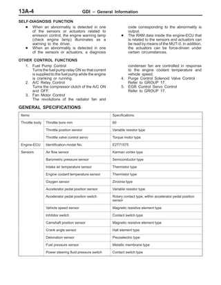
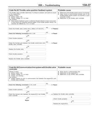
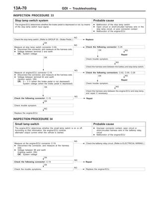
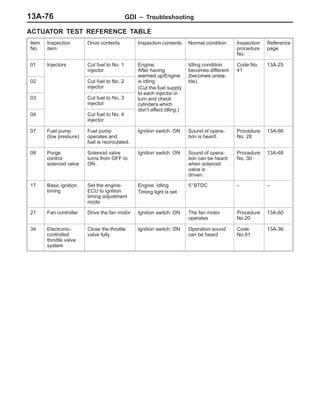
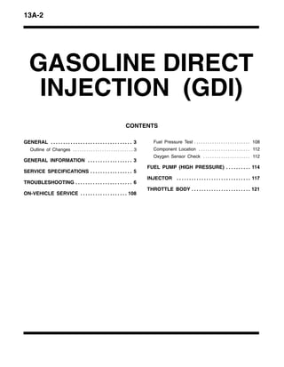
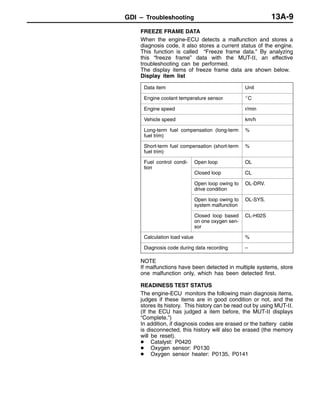
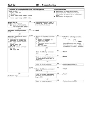
GASOLINE DIRECT INJECTION SYSTEM DIAGRAM
*1 Oxygen sensor
*2 Air flow sensor
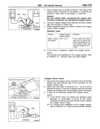
*3 Intake air temper-
ature senor
*4 Throttle position
sensor (2nd chan-
nel)
*5 Camshaft position
sensor
*6 Crank angle sen-
sor
*7 Barometric pres-
sure sensor
*8 Engine coolant
temperature sen-
sor
*9 Detonation sensor
*10 Fuel pressure sen-
sor
*11 Throttle position
sensor (1st chan-
nel)
D Power supply
D Ignition switch – IG
D Ignition switch – ST
D Accelerator pedal posi-
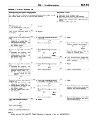
tion sensor (1st
channel)
D Accelerator pedal posi-
tion switch
D Vehicle speed sensor
D A/C switch
D A/C thermo sensor
D Inhibitor switch
D Power steering fluid
pressure switch
D Alternator FR terminal
D Stop lamp switch
D Small lamp switch
D Injector wire open circuit
check signal
D Throttle valve controller
D A/T-ECU
D Power supply
D Ignition switch – IG
D Accelerator pedal posi-
tion sensor (2nd chan-
nel)
D Engine-ECU
Engine-
ECU
From fuel pump
(low pressure)
To fuel tank
*10 Fuel pressure
sensor
*5 Camshaft position
sensor
*4 Throttle position sensor
(2nd channel)
*11 Throttle position sensor
(1st channel)
z4 Throttle valve
control servo
*3 Intake airtemperature
sensor
*2 Air flow sensor
*7 Barometric
pressure sensor
z2 EGR valve
(Stepper
motor)
High-pressure fuel
regulator assembly
[integrated in fuel
pressure regulator
(high pressure)]
Fuel pump
(high pressure)
Injector
z1 Injector
driver
*8 Engine coolant
temperature sensor
*9 Detonation sensor
*1 Oxygen sensor
*6 Crank angle sensor
Canister
z3 Purge control
solenoid valve
z1 Injector driver (In-
jector)
z2 EGR valve (Step-
per motor)
z3 Purge control sole-
noid valve
z4 Throttle valve con-
trol servo
D Engine control relay
D Fuel pump relay
D Injector driver relay
D Throttle valve control
servo relay
D A/C relay
D Ignition coil
D Fan controller
D GDI ECO indicator lamp
D Engine warning lamp
D Diagnosis output
D Alternator G terminal
D Throttle valve controller
D A/T-ECU
D Engine-ECU
Throttle
valve
control-
ler](https://image.slidesharecdn.com/13agasolinedirectinjectiongdi-160205191742/85/13-a-gasoline-direct-injection-gdi-6-320.jpg)
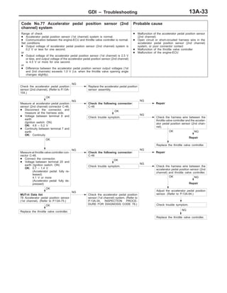

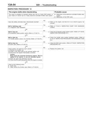
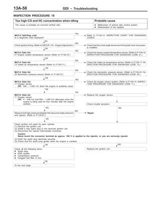
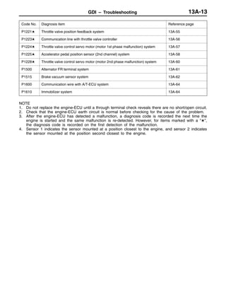
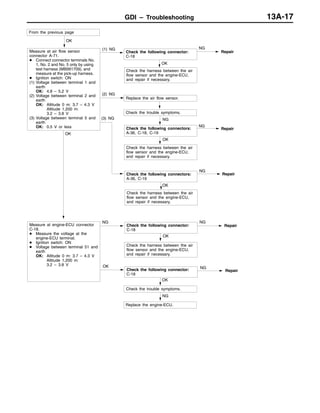
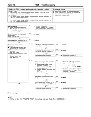
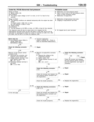
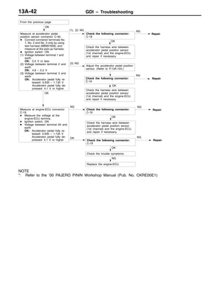
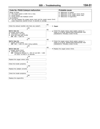
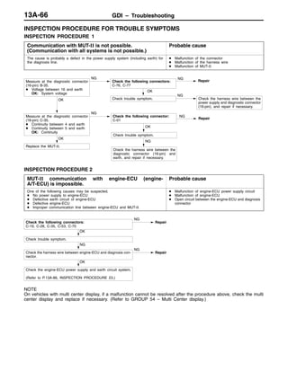
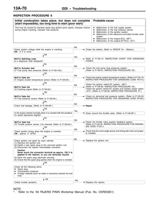
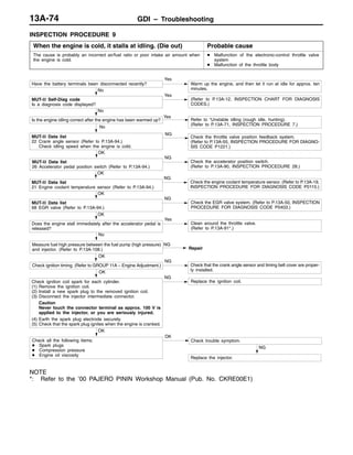
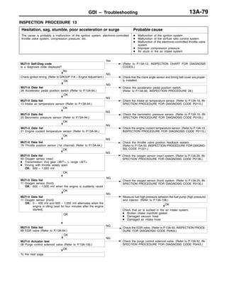
![GDI – Troubleshooting 13A-71
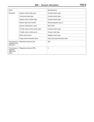
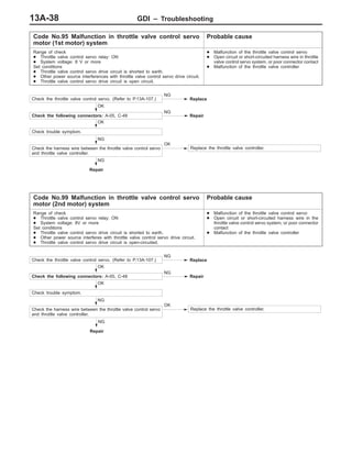
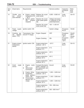
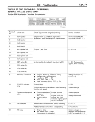
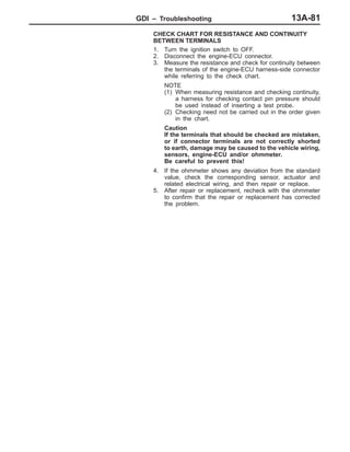
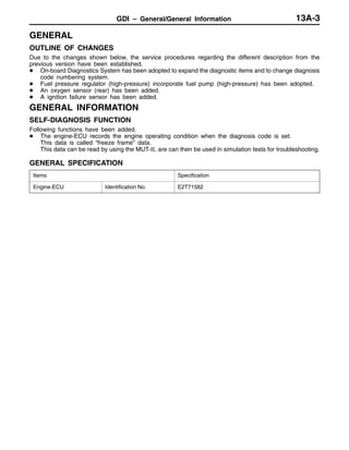
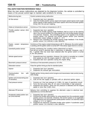
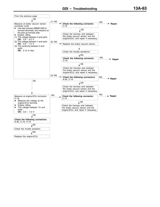
DATA LIST REFERENCE TABLE
Caution
When shifting the select lever to D range, the brakes should be applied so that the vehicle does
not move forward.
NOTE
*1: Within four minutes after starting the engine
*2: In a new vehicle [driven approximately 500 km or less], the injector drive time is sometimes 10% longer
than the standard time.
*3: The accelerator pedal position switch normally turns off when the voltage of the accelerator pedal
position sensor (1st channel) is 250 – 550 mV higher than the voltage at the idle position. If the accelerator
pedal position switch turns back on after the accelerator pedal position sensor voltage has risen by
100 mV and the throttle valve has opened, the accelerator pedal position switch and the accelerator
pedal position sensor (1st channel) need to be adjusted.
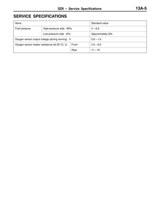
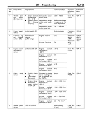
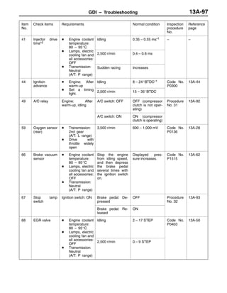
Item
No.
Check items Requirements Normal condition Inspection
procedure
No.
Refer-
ence
page
11 Oxygen sensor Engine: After warm-
up
Idling 0 mV*1 Code
No 11
13A-15
up
Sudden racing 600 – 1,000 mV
No.11
2,500 r/min 400 mV or less ↔
600 – 1,000 mV
(alternates)
12 Air flow sensor D Engine coolant
temperature: 80
– 95_C
Idling 20 – 55 Hz Code
No.12
13A-16
– 95_C
D Lamps, electric
cooling fan and
all accessories:
2,500 r/min 65 – 85 Hz
all accessories:
OFF
D Transmission:
Neutral (A/T: P
range)
Racing Frequency in-
creases in re-
sponse to racing.
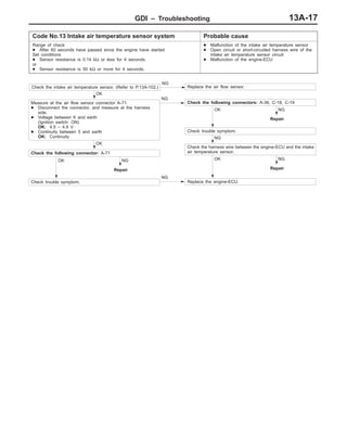
13 Intake air tem-
perature sen-
sor
Ignition switch: ON Intake air tempera-
ture: –20_C
–20_C Code
No.13
13A-17
sor
Intake air tempera-
ture: 0_C
0_C
Intake air tempera-
ture: 20_C
20_C
Intake air tempera-
ture: 40_C
40_C
Intake air tempera-
ture: 80_C
80_C](https://image.slidesharecdn.com/13agasolinedirectinjectiongdi-160205191742/85/13-a-gasoline-direct-injection-gdi-71-320.jpg)
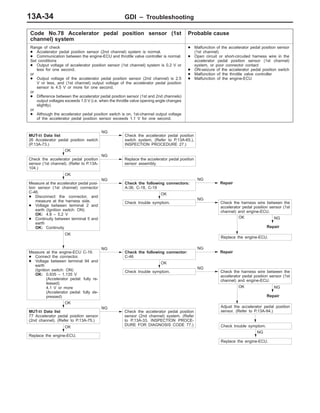
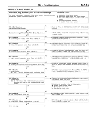
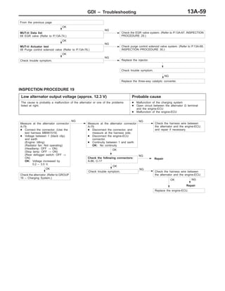
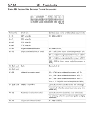
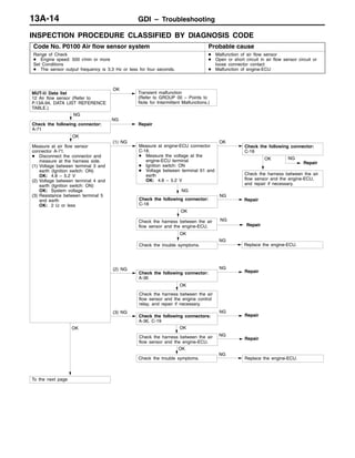
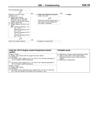
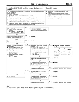
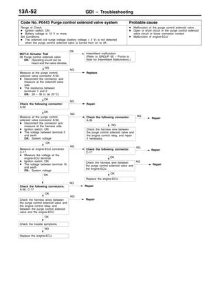
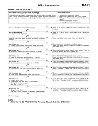
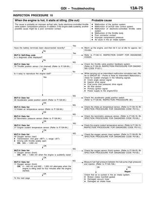
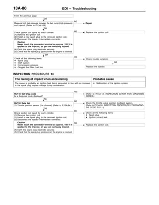
![GDI – Troubleshooting 13A-73
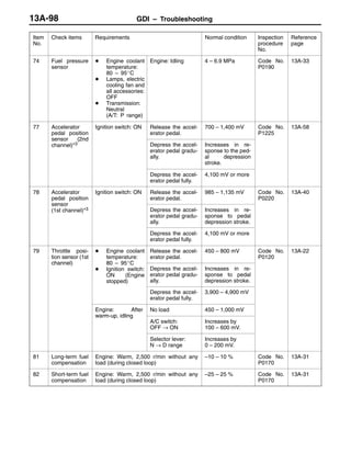
Item
No.
Refer-
ence
page
Inspection
procedure
No.
Normal conditionRequirementsCheck items
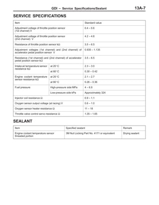
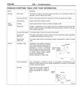
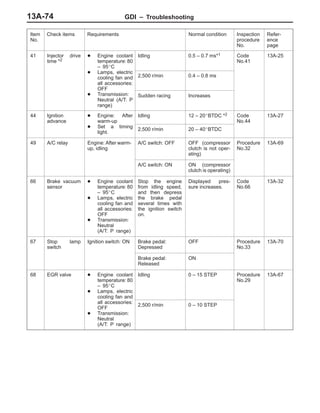
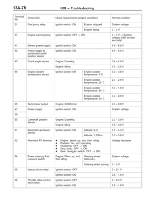
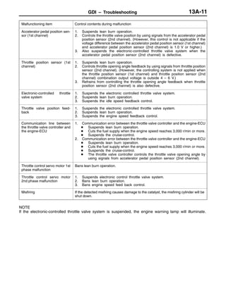
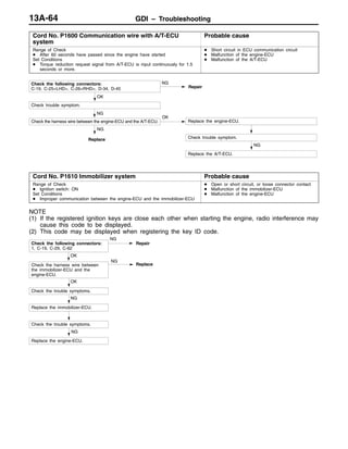
25 Barometric
pressure sen-
Ignition switch: ON Altitude: 0 m 101 kPa Code
No 25
13A-23
pressure sen-
sor Altitude: 600 m 95 kPa
No.25
Altitude: 1,200 m 88 kPa
Altitude: 1,800 m 81 kPa
26 Accelerator
pedal position
switch
Ignition switch: ON
(Depress and re-
lease the accelera-
Release the accel-
erator pedal.
ON Procedure
No.27
13A-65
switch lease the accelera-
tor pedal several
times)
Depress the accel-
erator pedal slightly.
OFF
27 Power steering
fluid pressure
switch
Engine: Idling Steering wheel sta-
tionary
OFF Procedure
No.31
13A-69
switch
Steering wheel
turning
ON
28 A/C switch Engine: Idling (The
A/C compressor is
A/C switch: OFF OFF Procedure
No.32
13A-69
A/C com ressor is
running when the
A/C switch is on.)
A/C switch: ON ON
No.32
29 Inhibitor switch
<A/T>
Ignition switch: ON Selector lever: P or
N
P, N Procedure
No.26
13A-64
Selector lever: D, 2,
L or R
D, 2, L, R
31 Small lamp
switch
Engine: Idling Lighting switch:
OFF
OFF Procedure
No.34
13A-70
Lighting switch: ON ON
34 Air flow sensor
reset signal
Engine: After hav-
ing warmed up
Engine is idling ON Code
No 12
13A-16
reset signal ing warmed up
3,000 r/min OFF
No.12
37 Volumetric effi-
ciency
D Engine coolant
temperature: 80
– 95_C
Engine is idling 30 – 50% – –
– 95_C
D Lamps, electric
cooling fan and
all accessories:
2,500 r/min 30 – 50%
all accessories:
OFF
D Transmission:
Neutral
(A/T: P range)
Engine is suddenly
raced
Volumetric effi-
ciency increases in
response to racing
38 Crank angle
sensor
D Engine: Cranking [reading is possible
at 2,000 r/min or less]
D Tachometer: Connected
Engine speeds dis-
played on the
MUT-II and
tachometer are
identical.
– –](https://image.slidesharecdn.com/13agasolinedirectinjectiongdi-160205191742/85/13-a-gasoline-direct-injection-gdi-73-320.jpg)
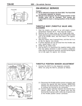
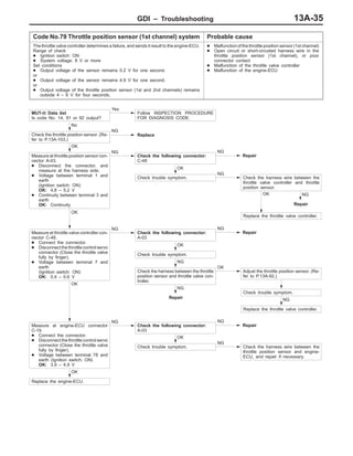
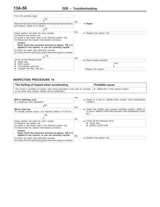
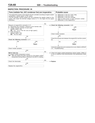
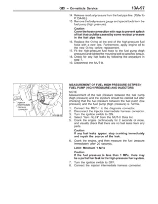
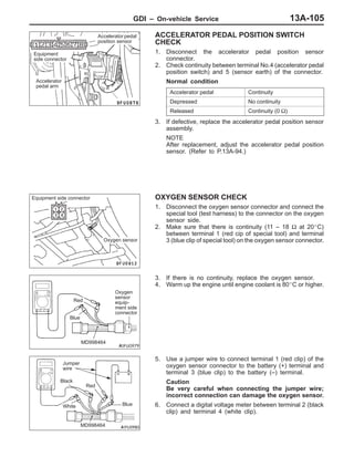
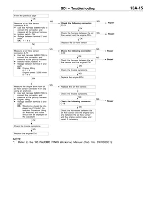
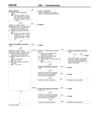
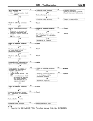
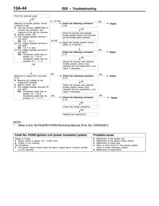
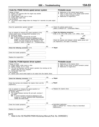
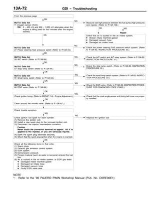
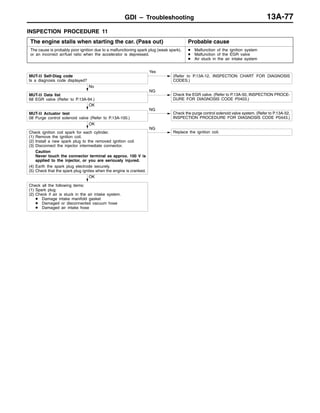
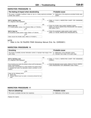
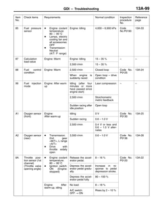
![GDI – On-vehicle Service13A-94
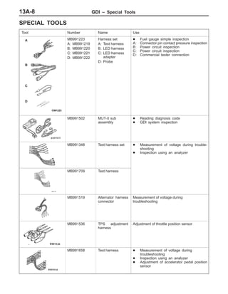
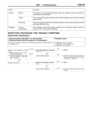
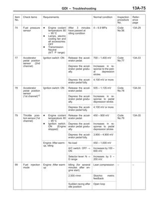
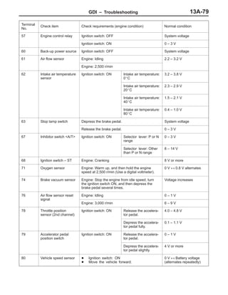
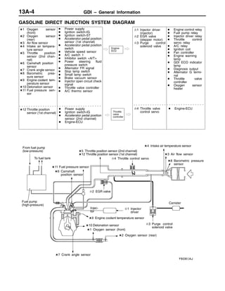
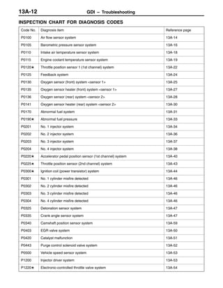
ACCELERATOR PEDAL POSITION SENSOR
ADJUSTMENT
Caution
(1) Never attempt to tamper the accelerator pedal position
sensor. The sensor position is precisely adjusted at
factory.
(2) Should it be tampered, follow the procedure below:
1. Connect the MUT-II to the diagnosis connector.
When not using the MUT-II, proceed as follows:
(1) Disconnect the accelerator pedal position sensor
connector. Connect the special tool (test harness:
MB991658) between the disconnected connectors,
and then connect the digital voltmeter to the terminal
No.3 [output terminal of accelerator pedal position
sensor (1st channel)] and to the terminal No.1 [earth
terminal of accelerator pedal position sensor (1st
channel)].
2. Loosen the accelerator pedal position sensor installation
bolts.
3. Contact the accelerator pedal arm to the stopper.
4. Turn the ignition switch to the ON position (but do not
start the engine).
5. Rotate the accelerator pedal position sensor with the knock
pin as the centre, and adjust the output voltage of the
accelerator pedal position sensor (1st channel) to the
standard value.
Standard value: 0.935 – 1.135 V
6. Tighten the accelerator pedal position sensor installation
bolts fully.
Equipment
side connector
Accelerator pedal
position sensor
Accelerator
pedal arm
MB991658
Accelerator pedal
position sensor
Stopper
Accelerator
pedal arm
Accelerator
pedal assembly
Accelerator pedal
position sensor
Knock pin](https://image.slidesharecdn.com/13agasolinedirectinjectiongdi-160205191742/85/13-a-gasoline-direct-injection-gdi-94-320.jpg)
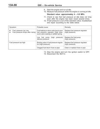

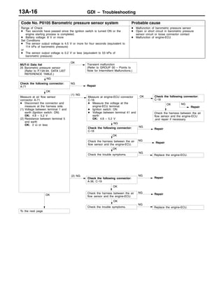
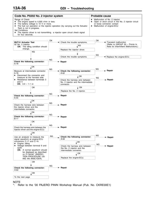

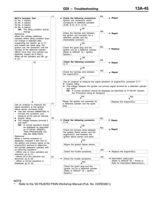
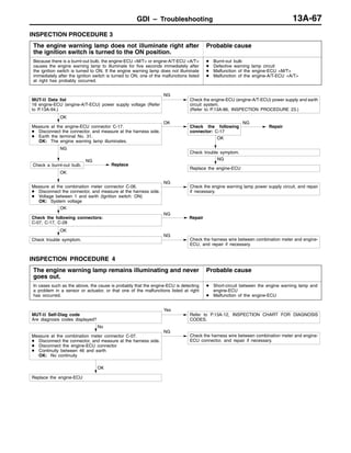

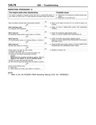
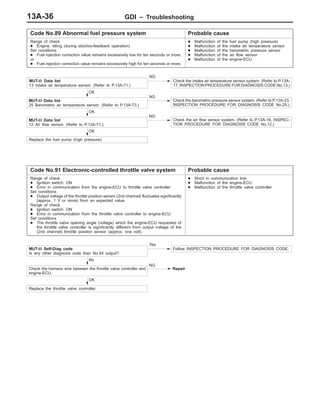
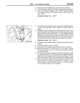
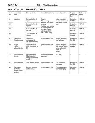
![GDI – Troubleshooting13A-94
DATA LIST REFERENCE TABLE
Caution
When shifting the select lever to D range, the brakes should be applied so that the vehicle does
not move forward.
NOTE
*1: Within four minutes after starting the engine
*2: In a new vehicle [driven approximately 500 km or less], the injector drive time is sometimes 10 %
longer than the standard time.
*3: The accelerator pedal position switch normally turns off when the voltage of the accelerator pedal
position sensor (1st channel) is 200 – 600 mV higher than the voltage at the idle position. If the accelerator
pedal position switch turns back on after the accelerator pedal position sensor voltage has risen by
100 mV and the throttle valve has opened, the accelerator pedal position switch and the accelerator
pedal position sensor (1st channel) need to be adjusted.
Item
No.
Check items Requirements Normal condition Inspection
procedure
No.
Reference
page
11 Oxygen sensor
(front)
Engine: After
warm-up
Idling 0 mV*1 Code No.
P0130
13A-25
(front) warm-up
Sudden racing 600 – 1,000 mV
P0130
2,500 r/min 400 mV or less and
600 – 1,000 mV
alternates.
12 Air flow sensor D Engine coolant
temperature:
80 – 95_C
Idling 24 – 50 Hz Code No.
P0100
13A-14
80 – 95_C
D Lamps, electric
cooling fan and
all accessories:
2,500 r/min 70 – 90 Hz
all accessories:
OFF
D Transmission:
Neutral
(A/T: P range)
Racing Frequency in-
creases in re-
sponse to racing.
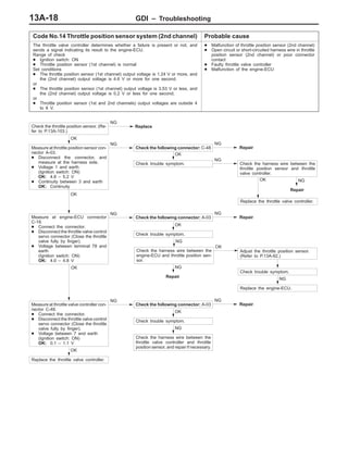
13 Intake air tem-
perature sen-
sor
Ignition switch: ON Intake air tempera-
ture: –20_C
–20_C Code No.
P0110
13A-18
sor
Intake air tempera-
ture: 0_C
0_C
Intake air tempera-
ture: 20_C
20_C
Intake air tempera-
ture: 40_C
40_C
Intake air tempera-
ture: 80_C
80_C](https://image.slidesharecdn.com/13agasolinedirectinjectiongdi-160205191742/85/13-a-gasoline-direct-injection-gdi-211-320.jpg)
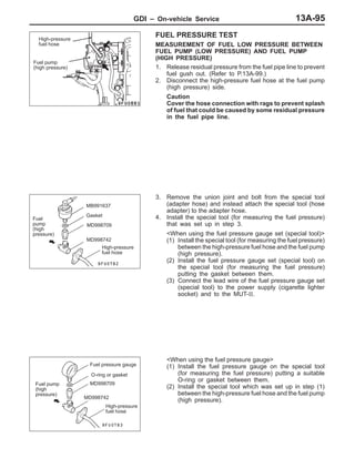
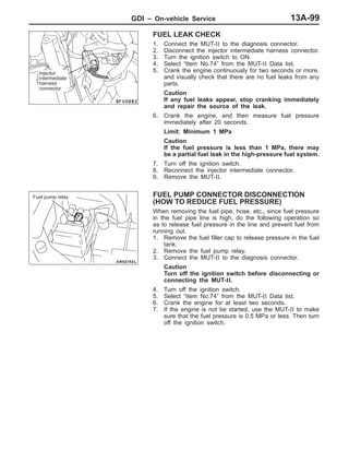
![GDI – Troubleshooting13A-96
Item
No.
Reference
page
Inspection
procedure
No.
Normal conditionRequirementsCheck items
25 Barometric
pressure sen-
Ignition switch: ON Altitude: 0 m 101 kPa Code No.
P0105
13A-16
pressure sen-
sor Altitude: 600 m 95 kPa
P0105
Altitude: 1,200 m 88 kPa
Altitude: 1,800 m 81 kPa
26 Accelerator
pedal position
switch
Ignition switch: ON
(Depress and re-
lease the accelera-
Release the accel-
erator pedal.
ON Procedure
No. 28
13A-90
switch lease the accelera-
tor pedal several
times)
Depress the accel-
erator pedal slight-
ly.
OFF
27 Power steering
fluid pressure
switch
Engine: Idling Steering wheel sta-
tionary
OFF Procedure
No. 30
13A-92
switch
Steering wheel
turning
ON
28 A/C switch Engine: Idling (The
A/C compressor is
A/C switch: OFF OFF Procedure
No. 31
13A-92
A/C com ressor is
running when the
A/C switch is on.)
A/C switch: ON ON
No. 31
29 Inhibitor switch
<A/T>
Ignition switch: ON Selector lever: P or
N
P, N Procedure
No. 27
13A-89
Selector lever: D, 2,
L or R
D, 2, L, R
31 Small lamp
switch
Engine: Idling Lighting switch:
OFF
OFF Procedure
No. 33
13A-93
Lighting switch: ON ON
34 Air flow sensor
reset signal
Engine: After hav-
ing warmed up
Engine is idling ON Code No.
P0100
13A-14
reset signal ing warmed up
3,000 r/min OFF
P0100
37 Volumetric effi-
ciency
D Engine coolant
temperature:
80 – 95_C
Engine is idling 30 – 50 % – –
80 – 95_C
D Lamps, electric
cooling fan and
all accessories:
2,500 r/min 10 – 30 %
all accessories:
OFF
D Transmission:
Neutral
(A/T: P range)
Engine is suddenly
raced
Volumetric effi-
ciency increases in
response to racing
38 Crank angle
sensor
D Engine: Cranking [reading is possible
at 2,000 r/min or less]
D Tachometer: Connected
Engine speeds dis-
played on the
MUT-II and
tachometer are
identical.
– –](https://image.slidesharecdn.com/13agasolinedirectinjectiongdi-160205191742/85/13-a-gasoline-direct-injection-gdi-213-320.jpg)

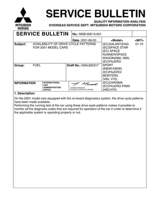
![3
DRIVE CYCLE
Performing the running test of the car using the following five drive cycle patterns makes it possible to
monitor all the diagnosis codes that are required for operation of the car in order to determine if the
applicable system is operating properly or not.
In other words, doing such a drive allows to regenerate any kind of trouble which involves illuminating the
Engine Warning Lamp (Check Engine Lamp) and to verify the repair procedure has eliminated the trouble
[the Engine Warning Lamp (Check Engine Lamp) is no longer illuminated].
Caution
Two technicians should always be in the vehicle when carrying out a test drive.
NOTE
Check that the diagnosis code is not output before traveling in the Drive cycle pattern. Erase the diagnosis
code if it has been output.
DRIVE CYCLE PATTERN LIST
PROCEDURE MONITOR ITEM DIAGNOSIS CODE
1 Catalytic converter monitor P0420
2 Heated oxygen sensor <front> monitor P0130
3 Fuel trim monitor P0170
4 Feed back monitor P0125
5 Other monitor P0136, P0201, P0202, P0203, P0204, P0300,
P0301, P0302, P0303, P0304, P0325
NOTE
The vehicle speed sensor (P0500) and the power steering fluid pressure switch (P0551) are used to
determine if the system is operating properly or not through use of the Data List function of the MUT-II.
3. Details:2001 GALANT Workshop Manual Supplement 4G64
2001 SPACE RUNNER/SPACE WAGON Workshop Manual Supplement 4G64
GDI - Troubleshooting](https://image.slidesharecdn.com/13agasolinedirectinjectiongdi-160205191742/85/13-a-gasoline-direct-injection-gdi-243-320.jpg)
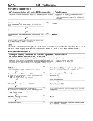
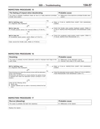
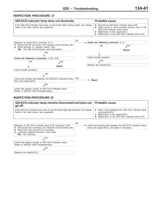
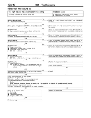
![4
PROCEDURE 1
Monitor item CATALYTIC CONVERTER MONITOR (P0420)
One trip monitor [from start to ignition switch to “LOCK” (OFF) position] will be completed while
traveling with the following drive cycle pattern. It will take 10 minutes or more.
Drive cycle
pattern
Inspection
conditions
• Atmospheric temperature :-10 °C or more
• Condition of A/T :Selector lever D range, overdrive switch “ON” position
Test
procedure
1. Engine : start
2. Accelerate until the vehicle speed is 100 km/h or more.
3. Travel for 5 minutes or more while keeping the vehicle speed is 100 km/h or more.
4. Decelerate until the vehicle speed is 100 – 120 km/h or less.
5. While keeping the accelerator pedal opening degree constant, keep the vehicle speed at 100 –
120 km/h and travel for 5 minutes or more.
• Stopping and braking during this operation are permitted.
6. Return the vehicle to the shop, then turn the ignition switch “LOCK” (OFF) position.
2001 GALANT Workshop Manual Supplement 4G64
2001 SPACE RUNNER/SPACE WAGON Workshop Manual Supplement 4G64
GDI - Troubleshooting
Y6005BY
100 – 120 km/h
Vehicle
speed
5 minutes or more
100 km/h or more
Engine start
Stopping and
braking permitted
Ignition switch ”LOCK”
(OFF) position
Time
5 minutes or more](https://image.slidesharecdn.com/13agasolinedirectinjectiongdi-160205191742/85/13-a-gasoline-direct-injection-gdi-244-320.jpg)
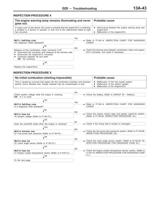
![5
PROCEDURE 2
OXYGEN SENSOR <FRONT> MONITOR (P0130)
One trip monitor [from start to ignition switch to “LOCK” (OFF) position] will be completed while
traveling with the following drive cycle pattern. It will take 5 minutes or more.
Drive cycle
pattern
Inspection
conditions
• Engine coolant temperature : 85 °C or more
• Atmospheric temperature : -10 °C or more
• Condition of A/T :Selector lever D range, overdrive switch “ON” position
Test
procedure
1. Engine : start
2. Accelerate until the vehicle speed is 80 – 100 km/h.
3. While keeping the accelerator pedal opening degree constant, keep the vehicle speed at 80 –
100 km/h and travel for 5 minutes or more.
• Stopping and braking during this operation are permitted. Keep the accelerator pedal
opening degree constant for 1 minute or more after each acceleration.
4. Return the vehicle to the shop, then turn the ignition switch “LOCK” (OFF) position.
2001 GALANT Workshop Manual Supplement 4G64
2001 SPACE RUNNER/SPACE WAGON Workshop Manual Supplement 4G64
GDI - Troubleshooting
Y6002BY
Vehicle
speed
5 minutes or more
80 – 100 km/h
Engine start
Stopping and
braking permitted
Ignition switch ”LOCK”
(OFF) position
Time](https://image.slidesharecdn.com/13agasolinedirectinjectiongdi-160205191742/85/13-a-gasoline-direct-injection-gdi-245-320.jpg)
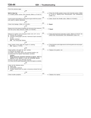
![6
PROCEDURE 3
monitor item FUEL TRIM MONITOR (P0170)
One trip monitor [from start to ignition switch to “LOCK” (OFF) position] will be completed while
traveling with the following drive cycle pattern. It will take 15 minutes or more.
Drive cycle
pattern
Inspection
conditions
• Engine coolant temperature : 85 °C or more
• Atmospheric temperature : -10 °C or more
• Condition of A/T :Selector lever D range, overdrive switch “ON” position
Test
procedure
1. Engine : start
2. Accelerate until the vehicle speed is 80 – 110 km/h.
3. While keeping the accelerator pedal opening degree constant, keep the vehicle speed at 80 –
110 km/h and travel for 15 minutes or more.
4. Return the vehicle to the shop, then turn the ignition switch “LOCK” (OFF) position.
2001 GALANT Workshop Manual Supplement 4G64
2001 SPACE RUNNER/SPACE WAGON Workshop Manual Supplement 4G64
GDI - Troubleshooting
Y6002BY
Vehicle
speed
15 minutes or more
80 – 110 km/h
Engine start
Stopping and
braking permitted
Ignition switch ”LOCK”
(OFF) position
Time](https://image.slidesharecdn.com/13agasolinedirectinjectiongdi-160205191742/85/13-a-gasoline-direct-injection-gdi-246-320.jpg)
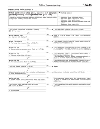
![7
PROCEDURE 4
monitor item FEED BACK MONITOR (PO125)
One trip monitor [from start to ignition switch to “LOCK” (OFF) position] will be completed while
traveling with the following drive cycle pattern. It will take 5 minutes or more.
Drive cycle
pattern
Inspection
conditions
• Engine coolant temperature : 85 °C or more
• Atmospheric temperature : -10 °C or more
• Condition of A/T :Selector lever D range, overdrive switch “ON” position
Test
procedure
1. Engine : start
2. Accelerate until the vehicle speed is 100 – 120 km/h.
3. While keeping the accelerator pedal opening degree constant, keep the vehicle speed at 100 –
120 km/h and travel for 5 minutes or more.
4. Return the vehicle to the shop, then turn the ignition switch “LOCK” (OFF) position.
2001 GALANT Workshop Manual Supplement 4G64
2001 SPACE RUNNER/SPACE WAGON Workshop Manual Supplement 4G64
GDI - Troubleshooting
Y6002BY
Vehicle
speed
5 minutes or more
100 – 120 km/h
Engine start
Stopping and
braking permitted
Ignition switch ”LOCK”
(OFF) position
Time](https://image.slidesharecdn.com/13agasolinedirectinjectiongdi-160205191742/85/13-a-gasoline-direct-injection-gdi-247-320.jpg)
![8
PROCEDURE 5
monitor item OTHER MONITOR
Diagnosis
code No.
P0136, P0201, P0202, P0203, P0204, P0300, P0301, P0302, P0303, P0304, P0325
One trip monitor [from start to ignition switch to “LOCK” (OFF) position] will be completed while
traveling with the following drive cycle pattern. It will take 6 minutes or more.
Drive cycle
pattern
Inspection
conditions
• Engine coolant temperature : 85 °C or more
• Atmospheric temperature : -10 °C or more
• Condition of A/T :Selector lever D range, overdrive switch “ON” position
Test
procedure
1. Engine : start
2. Accelerate until the vehicle speed is 60 km/h.
3. While keeping the accelerator pedal opening degree constant, keep the vehicle speed at
60km/h or more and travel for 5 minutes or more.
4. Return the vehicle to the shop
5. After stopping the vehicle, continue idling for 30 seconds, and then turn the ignition switch to
”LOCK” (OFF) position.
• A/C switch : OFF
• Light and all accessories : OFF
• Transmission : Neutral
2001 GALANT Workshop Manual Supplement 4G64
2001 SPACE RUNNER/SPACE WAGON Workshop Manual Supplement 4G64
GDI - Troubleshooting
Y6009BY
Vehicle
speed
5 minutes or more
60 km/h or more
Engine start
30 seconds or more
Engine: Idling
Transmission: Neutral
Ignition switch ”LOCK”
(OFF) position
Time](https://image.slidesharecdn.com/13agasolinedirectinjectiongdi-160205191742/85/13-a-gasoline-direct-injection-gdi-248-320.jpg)
![9
DRIVE CYCLE
Performing the running test of the car using the following five drive cycle patterns makes it possible to
monitor all the diagnosis codes that are required for operation of the car in order to determine if the
applicable system is operating properly or not.
In other words, doing such a drive allows to regenerate any kind of trouble which involves illuminating the
Engine Warning Lamp (Check Engine Lamp) and to verify the repair procedure has eliminated the trouble
[the Engine Warning Lamp (Check Engine Lamp) is no longer illuminated].
Caution
Two technicians should always be in the vehicle when carrying out a test drive.
NOTE
Check that the diagnosis code is not output before traveling in the Drive cycle pattern. Erase the diagnosis
code if it has been output.
DRIVE CYCLE PATTERN LIST
PROCEDURE MONITOR ITEM DIAGNOSIS CODE
Catalytic converter monitor P04201
Catalyst temperature sensor <M/T> monitor
(DX only)
P0425
2 Heated oxygen sensor <front> monitor P0130
3 Fuel trim monitor P0170
4 Feed back monitor P0125
5 Other monitor P0136, P0201, P0202, P0203, P0204, P0300,
P0301, P0302, P0303, P0304, P0325
NOTE
The vehicle speed sensor (P0500) and the power steering fluid pressure switch (P0551) are used to
determine if the system is operating properly or not through use of the Data List function of the MUT-II.
2001 CARISMA Workshop Manual Supplement 4G93
2001 SPACE STAR Workshop Manual Supplement 4G93
GDI - Troubleshooting](https://image.slidesharecdn.com/13agasolinedirectinjectiongdi-160205191742/85/13-a-gasoline-direct-injection-gdi-249-320.jpg)
![10
PROCEDURE 1
CATALYTIC CONVERTER MONITOR (P0420)monitor item
CATALYTIC TEMPERATURE SENSOR <M/T> MONITOR (P0425)
One trip monitor [from start to ignition switch to “LOCK” (OFF) position] will be completed while
traveling with the following drive cycle pattern. It will take 12 minutes or more.
Drive cycle
pattern
Inspection
conditions
• Engine coolant temperature : 85 °C or more
• Atmospheric temperature : -10 °C or more
• Condition of A/T :Selector lever D range, overdrive switch “ON” position
Test
procedure
1. Engine : start
2. Accelerate until the vehicle speed is 100 km/h.
3. Travel for 5 minutes or more while keeping the vehicle speed is 100 km/h or more.
4. Decelerate until the vehicle speed is 0 km/h within 1 minute and stop for 25 – 30 seconds.
5. Accelerate until the vehicle speed at 100 – 120 km/h within 1 minute.
6. While keeping the accelerator pedal opening degree constant, keep the vehicle speed at
100 - 120 km/h and travel for 3 minutes or more.
7. Repeat the above procedure 4 – 6.
8. Return the vehicle to the shop, then turn the ignition switch ”LOCK” (OFF) position.
2001 CARISMA Workshop Manual Supplement 4G93
2001 SPACE STAR Workshop Manual Supplement 4G93
GDI - Troubleshooting
Y6004BY
Vehicle
speed 5 minutes or more
100 km/h or more
Engine start
Ignition switch
”LOCK” (OFF)
position
Time
*: 1 minute or less
3 minutes or more 3 minutes or more
100 – 120 km/h 100 – 120 km/h
Stop: 25 – 30 seconds Stop: 25 – 30 seconds](https://image.slidesharecdn.com/13agasolinedirectinjectiongdi-160205191742/85/13-a-gasoline-direct-injection-gdi-250-320.jpg)
![11
PROCEDURE 2
monitor item OXYGEN SENSOR <FRONT> MONITOR (P0130)
One trip monitor [from start to ignition switch to “LOCK” (OFF) position] will be completed while
traveling with the following drive cycle pattern. It will take 7 minutes or more.
Drive cycle
pattern
Inspection
conditions
• Engine coolant temperature : 85 °C or more
• Atmospheric temperature : -10 °C or more
• Condition of A/T :Selector lever D range, overdrive switch “ON” position
Test
procedure
1. Engine : start
2. Accelerate until the vehicle speed is 100 – 120 km/h within 1 minute.
3. While keeping the accelerator pedal opening degree constant, keep the vehicle speed at 100 –
120 km/h and travel for 3 minutes or more.
4. Decelerate until the vehicle speed is 0 km/h within 1 minute and stop for 25 – 30 seconds.
5. Repeat the above procedure 2 – 3.
6. Return the vehicle to the shop, then turn the ignition switch “LOCK” (OFF) position.
2001 CARISMA Workshop Manual Supplement 4G93
2001 SPACE STAR Workshop Manual Supplement 4G93
GDI - Troubleshooting
Y6006BY
Vehicle
speed
3 minutes or more
100 – 120 km/h
Engine start
Stop: 25 – 30 seconds
Ignition switch
”LOCK” (OFF)
position
Time
*: 1 minute or less
3 minutes or more
100 – 120 km/h](https://image.slidesharecdn.com/13agasolinedirectinjectiongdi-160205191742/85/13-a-gasoline-direct-injection-gdi-251-320.jpg)
![12
PROCEDURE 3
monitor item FUEL TRIM MONITOR (P0170)
One trip monitor [from start to ignition switch to “LOCK” (OFF) position] will be completed while
traveling with the following drive cycle pattern. It will take 13 minutes or more.
Drive cycle
pattern
Inspection
conditions
• Engine coolant temperature : 85 °C or more
• Atmospheric temperature : -10 °C or more
• Condition of A/T :Selector lever D range, overdrive switch “ON” position
Test
procedure
1. Engine : start
2. Accelerate until the vehicle speed is 100 – 120 km/h within 1 minute.
3. While keeping the accelerator pedal opening degree constant, keep the vehicle speed at 100 –
120 km/h and travel for 3 minutes or more.
4. Decelerate until the vehicle speed is 0 km/h within 1 minute and stop for 25 – 30 seconds.
5. Repeat the above procedure 2 - 4 two times and 2 - 3 one time.
6. Return the vehicle to the shop, then turn the ignition switch “LOCK” (OFF) position.
2001 CARISMA Workshop Manual Supplement 4G93
2001 SPACE STAR Workshop Manual Supplement 4G93
GDI - Troubleshooting
Y6007BY
Vehicle
speed
3 minutes or more
100 – 120 km/h
Engine start
Stop: 25 – 30 seconds
Ignition switch
”LOCK” (OFF)
position
Time
*: 1 minute or less
3 minutes or more
100 – 120 km/h 100 – 120 km/h 100 – 120 km/h
3 minutes or more 3 minutes or more
Stop: 25 – 30 seconds Stop: 25 – 30 seconds](https://image.slidesharecdn.com/13agasolinedirectinjectiongdi-160205191742/85/13-a-gasoline-direct-injection-gdi-252-320.jpg)
![13
PROCEDURE 4
monitor item FEED BACK MONITOR (P0125)
One trip monitor [from start to ignition switch to “LOCK” (OFF) position] will be completed while
traveling with the following drive cycle pattern. It will take 5 minutes or more.
Drive cycle
pattern
Inspection
conditions
• Engine coolant temperature : 85 °C or more
• Atmospheric temperature : -10 °C or more
• Condition of A/T :Selector lever D range, overdrive switch “ON” position
Test
procedure
1. Engine : start
2. Accelerate until the vehicle speed is 90 – 110 km/h within 1 minute.
3. While keeping the accelerator pedal opening degree constant, keep the vehicle speed at 90 –
110 km/h and travel for 5 minutes or more.
4. Return the vehicle to the shop, then turn the ignition switch “LOCK” (OFF) position.
2001 CARISMA Workshop Manual Supplement 4G93
2001 SPACE STAR Workshop Manual Supplement 4G93
GDI - Troubleshooting
Y6008BY
Vehicle
speed
90 – 110 km/h
Engine start Ignition switch
”LOCK” (OFF)
position
Time
1 minute
or less
5 minutes or more
Stopping and
braking permitted](https://image.slidesharecdn.com/13agasolinedirectinjectiongdi-160205191742/85/13-a-gasoline-direct-injection-gdi-253-320.jpg)
![14
PROCEDURE 5
OTHER MONITOR
Diagnosis
code No.
P0136, P0201, P0202, P0203, P0204, P0300, P0301, P0302, P0303, P0304, P0325
One trip monitor [from start to ignition switch to “LOCK” (OFF) position] will be completed while
traveling with the following drive cycle pattern. It will take 6 minutes or more.
Drive cycle
pattern
Inspection
conditions
• Engine coolant temperature : 85 °C or more
• Atmospheric temperature : -10 °C or more
• Condition of A/T :Selector lever D range, overdrive switch “ON” position
Test
procedure
1. Engine : start
2. Accelerate until the vehicle speed is 60 km/h.
3. While keeping the accelerator pedal opening degree constant, keep the vehicle speed at
60km/h or more and travel for 5 minutes or more.
4. Return the vehicle to the shop
5. After stopping the vehicle, continue idling for 30 seconds, and then turn the ignition switch to
”LOCK” (OFF) position.
• A/C switch : OFF
• Light and all accessories : OFF
• Transmission : Neutral
2001 CARISMA Workshop Manual Supplement 4G93
2001 SPACE STAR Workshop Manual Supplement 4G93
GDI - Troubleshooting
Y6009BY
Vehicle
speed
5 minutes or more
60 km/h or more
Engine start
30 seconds or more
Engine: Idling
Transmission: Neutral
Ignition switch ”LOCK”
(OFF) position
Time](https://image.slidesharecdn.com/13agasolinedirectinjectiongdi-160205191742/85/13-a-gasoline-direct-injection-gdi-254-320.jpg)
![15
DRIVE CYCLE
Performing the running test of the car using the following five drive cycle patterns makes it possible to
monitor all the diagnosis codes that are required for operation of the car in order to determine if the
applicable system is operating properly or not.
In other words, doing such a drive allows to regenerate any kind of trouble which involves illuminating the
Engine Warning Lamp (Check Engine Lamp) and to verify the repair procedure has eliminated the trouble
[the Engine Warning Lamp (Check Engine Lamp) is no longer illuminated].
Caution
Two technicians should always be in the vehicle when carrying out a test drive.
NOTE
Check that the diagnosis code is not output before traveling in the Drive cycle pattern. Erase the diagnosis
code if it has been output.
DRIVE CYCLE PATTERN LIST
PROCEDURE MONITOR ITEM DIAGNOSIS CODE
Catalytic converter monitor P04201
Heated oxygen sensor <front> monitor P0130
2 Fuel trim monitor P0170
3 Feed back monitor P0125
4 Other monitor P0136, P0201, P0202, P0203, P0204, P0205,
P0206, P0300, P0301, P0302, P0303, P0304,
P0305, P0306, P0325
NOTE
The vehicle speed sensor (P0500) and the power steering fluid pressure switch (P0551) are used to
determine if the system is operating properly or not through use of the Data List function of the MUT-II.
2001 PAJERO/MONTERO WAGON Workshop Manual 6G74
GDI - Troubleshooting](https://image.slidesharecdn.com/13agasolinedirectinjectiongdi-160205191742/85/13-a-gasoline-direct-injection-gdi-255-320.jpg)
![16
PROCEDURE 1
CATALYTIC CONVERTER MONITOR (P0420)monitor item
OXYGEN SENSOR <FRONT> MONITOR (P0130)
One trip monitor [from start to ignition switch to “LOCK” (OFF) position] will be completed while
traveling with the following drive cycle pattern. It will take 10 minutes or more.
Drive cycle
pattern
Inspection
conditions
• Atmospheric temperature : -10 °C or more
• Condition of A/T :Selector lever D range, overdrive switch “ON” position
Test
procedure
1. Engine : start
2. Accelerate until the vehicle speed is 100 km/h or more.
3. Travel for 5 minutes or more while keeping the vehicle speed is 100 km/h or more.
4. Decelerate until the vehicle speed is 60 - 80 km/h or less.
5. While keeping the accelerator pedal opening degree constant, keep the vehicle speed at 60 - 80
km/h and travel for 5 minutes or more.
• Stopping and braking during this operation are permitted.
6. Return the vehicle to the shop, then turn the ignition switch ”LOCK” (OFF) position.
2001 PAJERO/MONTERO Workshop Manual 6G74
GDI - Troubleshooting
Y6005BY
Vehicle
speed
5 minutes or more
100 km/h or more
Engine start
Stopping and braking
permitted
Ignition switch
”LOCK” (OFF)
position
Time
5 minutes or more
60 – 80 km/h
100 – 120 km/h](https://image.slidesharecdn.com/13agasolinedirectinjectiongdi-160205191742/85/13-a-gasoline-direct-injection-gdi-256-320.jpg)
![17
PROCEDURE 2
monitor item FUEL TRIM MONITOR (P0170)
One trip monitor [from start to ignition switch to “LOCK” (OFF) position] will be completed while
traveling with the following drive cycle pattern. It will take 15 minutes or more.
Drive cycle
pattern
Inspection
conditions
• Engine coolant temperature : 85 °C or more
• Atmospheric temperature : -10 °C or more
• Condition of A/T :Selector lever D range, overdrive switch “ON” position
Test
procedure
1. Engine : start
2. Accelerate until the vehicle speed is 80 – 110 km/h.
3. While keeping the accelerator pedal opening degree constant, keep the vehicle speed at 80 –
110 km/h and travel for 15 minutes or more.
4. Return the vehicle to the shop, then turn the ignition switch “LOCK” (OFF) position.
2001 PAJERO/MONTERO Workshop Manual 6G74
GDI - Troubleshooting
Y6002BY
Vehicle
speed
15 minutes or more
80 – 110 km/h
Engine start
Stopping and
braking permitted
Ignition switch ”LOCK”
(OFF) position
Time](https://image.slidesharecdn.com/13agasolinedirectinjectiongdi-160205191742/85/13-a-gasoline-direct-injection-gdi-257-320.jpg)
![18
PROCEDURE 3
monitor item FEED BACKK MONITOR (P0125)
One trip monitor [from start to ignition switch to “LOCK” (OFF) position] will be completed while
traveling with the following drive cycle pattern. It will take 5 minutes or more.
Drive cycle
pattern
Inspection
conditions
• Engine coolant temperature : 85 °C or more
• Atmospheric temperature : -10 °C or more
• Condition of A/T :Selector lever D range, overdrive switch “ON” position
Test
procedure
1. Engine : start
2. Accelerate until the vehicle speed is 100 – 120 km/h.
3. While keeping the accelerator pedal opening degree constant, keep the vehicle speed at 100 –
120 km/h and travel for 5 minutes or more.
4. Return the vehicle to the shop, then turn the ignition switch “LOCK” (OFF) position.
2001 PAJERO/MONTERO Workshop Manual 6G74
GDI - Troubleshooting
Y6002BY
Vehicle
speed
5 minutes or more
100 – 120 km/h
Engine start
Stopping and
braking permitted
Ignition switch ”LOCK”
(OFF) position
Time](https://image.slidesharecdn.com/13agasolinedirectinjectiongdi-160205191742/85/13-a-gasoline-direct-injection-gdi-258-320.jpg)
![19
PROCEDURE 4
monitor item OTHER MONITOR
Diagnosis
code No.
P0136, P0201, P0202, P0203, P0204, P0205, P0206, P0300, P0301, P0302, P0303, P0304,
P0305, P0306, P0325
One trip monitor [from start to ignition switch to “LOCK” (OFF) position] will be completed while
traveling with the following drive cycle pattern. It will take 6 minutes or more.
Drive cycle
pattern
Inspection
conditions
• Engine coolant temperature : 85 °C or more
• Atmospheric temperature : -10 °C or more
• Condition of A/T :Selector lever D range, overdrive switch “ON” position
Test
procedure
1. Engine : start
2. Accelerate until the vehicle speed is 60 km/h.
3. While keeping the accelerator pedal opening degree constant, keep the vehicle speed at 60
km/h or more and travel for 5 minutes or more.
4. Return the vehicle to the shop
5. After stopping the vehicle, continue idling for 30 seconds, and then turn the ignition switch to
”LOCK” (OFF) position.
• A/C switch : OFF
• Light and all accessories: OFF
• Transmission : Neutral
2001 PAJERO/MONTERO Workshop Manual 6G74
GDI - Troubleshooting
Y6009BY
Vehicle
speed
5 minutes or more
60 km/h or more
Engine start
30 seconds or more
Engine: Idling
Transmission: Neutral
Ignition switch ”LOCK”
(OFF) position
Time](https://image.slidesharecdn.com/13agasolinedirectinjectiongdi-160205191742/85/13-a-gasoline-direct-injection-gdi-259-320.jpg)
![20
DRIVE CYCLE
Performing the running test of the car using the following five drive cycle patterns makes it possible to
monitor all the diagnosis codes that are required for operation of the car in order to determine if the
applicable system is operating properly or not.
In other words, doing such a drive allows to regenerate any kind of trouble which involves illuminating the
Engine Warning Lamp (Check Engine Lamp) and to verify the repair procedure has eliminated the trouble
[the Engine Warning Lamp (Check Engine Lamp) is no longer illuminated].
Caution
Two technicians should always be in the vehicle when carrying out a test drive.
NOTE
Check that the diagnosis code is not output before traveling in the Drive cycle pattern. Erase the diagnosis
code if it has been output.
DRIVE CYCLE PATTERN LIST
PROCEDURE MONITOR ITEM DIAGNOSIS CODE
1 Catalytic converter monitor P0420
2 Heated oxygen sensor <front> monitor P0130
3 Fuel trim monitor P0170
4 Feed back monitor P0125
5 Other monitor P0136, P0201, P0202, P0203, P0204, P0300,
P0301, P0302, P0303, P0304, P0325
NOTE
The vehicle speed sensor (P0500) and the power steering fluid pressure switch (P0551) are used to
determine if the system is operating properly or not through use of the Data List function of the MUT-II.
2000 PAJERO/PININ Workshop Manual Supplement 4G93
GDI - Troubleshooting](https://image.slidesharecdn.com/13agasolinedirectinjectiongdi-160205191742/85/13-a-gasoline-direct-injection-gdi-260-320.jpg)
![21
PROCEDURE 1
monitor item CATALYTIC CONVERTER MONITOR (P0420)
One trip monitor [from start to ignition switch to “LOCK” (OFF) position] will be completed while
traveling with the following drive cycle pattern. It will take 10 minutes or more.
Drive cycle
pattern
Inspection
conditions
• Atmospheric temperature : -10 °C or more
• Condition of A/T :Selector lever D range, overdrive switch “ON” position
Test
procedure
1. Engine : start
2. Accelerate until the vehicle speed is 100 km/h or more.
3. Travel for 5 minutes or more while keeping the vehicle speed is 100 km/h or more.
4. Decelerate until the vehicle speed is 90 –110 km/h or less.
5. While keeping the accelerator pedal opening degree constant, keep the vehicle speed at 90 -
110 km/h and travel for 5 minutes or more.
• Stopping and braking during this operation are permitted.
6. Return the vehicle to the shop, then turn the ignition switch ”LOCK” (OFF) position.
2000 PAJERO/PININ Workshop Manual Supplement 4G93
GDI - Troubleshooting
Y6005BY
Vehicle
speed
5 minutes or more
100 km/h or more
Engine start
Stopping and braking
permitted
Ignition switch
”LOCK” (OFF)
position
Time
5 minutes or more
90 – 110 km/h
100 – 120 km/h](https://image.slidesharecdn.com/13agasolinedirectinjectiongdi-160205191742/85/13-a-gasoline-direct-injection-gdi-261-320.jpg)
![22
PROCEDURE 2
OXYGEN SENSOR <FRONT> MONITOR (P0130)
One trip monitor [from start to ignition switch to “LOCK” (OFF) position] will be completed while
traveling with the following drive cycle pattern. It will take 5 minutes or more.
Drive cycle
pattern
Inspection
conditions
• Engine coolant temperature : 85 °C or more
• Atmospheric temperature : -10 °C or more
• Condition of A/T :Selector lever D range, overdrive switch “ON” position
Test
procedure
1. Engine : start
2. Accelerate until the vehicle speed is 80 – 100 km/h.
3. While keeping the accelerator pedal opening degree constant, keep the vehicle speed at 80 –
100 km/h and travel for 5 minutes or more.
• Stopping and braking during this operation are permitted. Keep the accelerator pedal
opening degree constant for 1 minute or more after each acceleration.
4. Return the vehicle to the shop, then turn the ignition switch “LOCK” (OFF) position.
2000 PAJERO/PININ Workshop Manual Supplement 4G93
GDI - Troubleshooting
Y6002BY
Vehicle
speed
5 minutes or more
80 – 100 km/h
Engine start
Stopping and
braking permitted
Ignition switch ”LOCK”
(OFF) position
Time](https://image.slidesharecdn.com/13agasolinedirectinjectiongdi-160205191742/85/13-a-gasoline-direct-injection-gdi-262-320.jpg)
![23
PROCEDURE 3
Monitor item FUEL TRIM MONITOR (P0170)
One trip monitor [from start to ignition switch to “LOCK” (OFF) position] will be completed while
traveling with the following drive cycle pattern. It will take 15 minutes or more.
Drive cycle
pattern
Inspection
conditions
• Engine coolant temperature : 85 °C or more
• Atmospheric temperature : -10 °C or more
• Condition of A/T :Selector lever D range, overdrive switch “ON” position
Test
procedure
1. Engine : start
2. Accelerate until the vehicle speed is 80 – 100 km/h.
3. While keeping the accelerator pedal opening degree constant, keep the vehicle speed at 80 –
110 km/h and travel for 15 minutes or more.
4. Return the vehicle to the shop, then turn the ignition switch “LOCK” (OFF) position.
2000 PAJERO/PININ Workshop Manual Supplement 4G93
GDI - Troubleshooting
Y6002BY
Vehicle
speed
15 minutes or more
80 – 110 km/h
Engine start
Stopping and
braking permitted
Ignition switch ”LOCK”
(OFF) position
Time](https://image.slidesharecdn.com/13agasolinedirectinjectiongdi-160205191742/85/13-a-gasoline-direct-injection-gdi-263-320.jpg)
![24
PROCEDURE 4
Monitor item FEED BACK MONITOR (P0125)
One trip monitor [from start to ignition switch to “LOCK” (OFF) position] will be completed while
traveling with the following drive cycle pattern. It will take 5 minutes or more.
Drive cycle
pattern
Inspection
conditions
• Engine coolant temperature : 85 °C or more
• Atmospheric temperature : -10 °C or more
• Condition of A/T :Selector lever D range, overdrive switch “ON” position
Test
procedure
1. Engine : start
2. Accelerate until the vehicle speed is 100 – 120 km/h.
3. While keeping the accelerator pedal opening degree constant, keep the vehicle speed at 100 –
120 km/h and travel for 15 minutes or more.
4. Return the vehicle to the shop, then turn the ignition switch “LOCK” (OFF) position.
2000 PAJERO/PININ Workshop Manual Supplement 4G93
GDI - Troubleshooting
Y6002BY
Vehicle
speed
5 minutes or more
100 – 120 km/h
Engine start
Stopping and
braking permitted
Ignition switch ”LOCK”
(OFF) position
Time](https://image.slidesharecdn.com/13agasolinedirectinjectiongdi-160205191742/85/13-a-gasoline-direct-injection-gdi-264-320.jpg)
![25
PROCEDURE 5
monitor item OTHER MONITOR
Diagnosis
code No.
P0136, P0201, P0202, P0203, P0204, P0300, P0301, P0302, P0303, P0304, P0325
One trip monitor [from start to ignition switch to “LOCK” (OFF) position] will be completed while
traveling with the following drive cycle pattern. It will take 6 minutes or more.
Drive cycle
pattern
Inspection
conditions
• Engine coolant temperature : 85 °C or more
• Atmospheric temperature : -10 °C or more
• Condition of A/T :Selector lever D range, overdrive switch “ON” position
Test
procedure
1. Engine : start
2. Accelerate until the vehicle speed is 60 km/h.
3. While keeping the accelerator pedal opening degree constant, keep the vehicle speed at 60
km/h or more and travel for 5 minutes or more.
4. Return the vehicle to the shop
5. After stopping the vehicle, continue idling for 30 seconds, and then turn the ignition switch to
”LOCK” (OFF) position.
• A/C switch : OFF
• Light and all accessories: OFF
• Transmission : Neutral
2000 PAJERO/PININ Workshop Manual Supplement 4G93
GDI - Troubleshooting
Y6009BY
Vehicle
speed
5 minutes or more
60 km/h or more
Engine start
30 seconds or more
Engine: Idling
Transmission: Neutral
Ignition switch ”LOCK”
(OFF) position
Time](https://image.slidesharecdn.com/13agasolinedirectinjectiongdi-160205191742/85/13-a-gasoline-direct-injection-gdi-265-320.jpg)
![26
DRIVE CYCLE
Performing the running test of the car using the following five drive cycle patterns makes it possible to
monitor all the diagnosis codes that are required for operation of the car in order to determine if the
applicable system is operating properly or not.
In other words, doing such a drive allows to regenerate any kind of trouble which involves illuminating the
Engine Warning Lamp (Check Engine Lamp) and to verify the repair procedure has eliminated the trouble
[the Engine Warning Lamp (Check Engine Lamp) is no longer illuminated].
Caution
Two technicians should always be in the vehicle when carrying out a test drive.
NOTE
Check that the diagnosis code is not output before traveling in the Drive cycle pattern. Erase the diagnosis
code if it has been output.
DRIVE CYCLE PATTERN LIST
PROCEDURE MONITOR ITEM DIAGNOSIS CODE (DTC)
1 Catalytic converter monitor P0420*
1
, P0421*
2
, P0431*
3
,
2 Heated oxygen sensor <front> monitor P0130
3 Other monitor P0136, P0201, P0202, P0203, P0204,
P0205*
3
, P0300, P0301, P0302, P0303,
P0304, P0305*
3
, P0306*
3
, P0325*
4
NOTE
*1: 4G63
*2: 4G13, 4G92, 4G93, 6A13, 6G72
*3: 6A13, 6G72
*4: 4G13, 4G63, 4G92, 4G93, 6A13
2001 GALANT Workshop Manual Supplement 4G63, 6A13
2001 SPACE RUNNER/SPACE WAGON Workshop Manual Supplement 4G63
2001 CARISMA Workshop Manual Supplement 4G92
2001 SPACE STAR Workshop Manual Supplement 4G13
2001 COLT Workshop Manual Supplement 4G13, 4G93
2001 PAJERO SPORT Workshop Manual Supplement 6G72
GDI - Troubleshooting](https://image.slidesharecdn.com/13agasolinedirectinjectiongdi-160205191742/85/13-a-gasoline-direct-injection-gdi-266-320.jpg)
![27
PROCEDURE 1
CATALYTIC CONVERTER MONITOR
Diagnosis
code No.
P0420, P0421, P0431
One trip monitor [from start to ignition switch to “LOCK” (OFF) position] will be completed while
traveling with the following drive cycle pattern. It will take 16 minutes or more.
Drive cycle
pattern
Inspection
conditions
• Atmospheric temperature : -10 °C or more
• Condition of A/T :Selector lever D range, overdrive switch “ON” position
Test
procedure
1. Engine : start
2. Accelerate until the vehicle speed is 90 km/h or more.
3. Travel for 6 minutes or more while keeping the vehicle speed is 90 km/h or more.
4. Decelerate until the vehicle speed is 80 km/h or less.
5. While traveling at 55 – 80 km/h for 10 minutes or more, fully close the throttle at least once in 2
minutes and decelerate for 10 seconds or more.
• Do not repeat deceleration too often.
• Vehicle speed may go below 55 km/h after the deceleration.
• Stopping and braking during this operation are permitted.
(If stopped or drive at 55 km/h or less for more than 5 minutes the monitoring may be
stopped. In this case please restart monitoring from the beginning.)
6. After completing the above deceleration, bring the vehicle speed back to 55 – 80 km/h and keep
it in the range until starting the deceleration again.
• Repeat the above deceleration at least 5 times.
7. Return the vehicle to the shop, the turn the ignition switch ”LOCK” (OFF) position.
2001 GALANT Workshop Manual Supplement 4G63, 6A13
2001 SPACE RUNNER/SPACE WAGON Workshop Manual Supplement 4G63
2001 CARISMA Workshop Manual Supplement 4G92
2001 SPACE STAR Workshop Manual Supplement 4G13
2001 COLT Workshop Manual Supplement 4G13, 4G93
2001 PAJERO SPORT Workshop Manual Supplement 6G72
GDI - Troubleshooting
Y6001BY
Vehicle
speed
6 minutes or more
90 km/h or more
Engine start
Stopping and braking
permitted
Ignition switch
”LOCK” (OFF)
position
Time
10 minutes or more
55 – 80 km/h](https://image.slidesharecdn.com/13agasolinedirectinjectiongdi-160205191742/85/13-a-gasoline-direct-injection-gdi-267-320.jpg)
![28
PROCEDURE 2
OXYGEN SENSOR <FRONT> MONITOR
Diagnosis
code No.
P0130
One trip monitor [from start to ignition switch to “LOCK” (OFF) position] will be completed while
traveling with the following drive cycle pattern. It will take 16 minutes or more.
Drive cycle
pattern
Inspection
conditions
• Engine coolant temperature : After engine warm up.
• Atmospheric temperature : -10 °C or more
• Condition of A/T :Selector lever D range, overdrive switch “ON” position
Test
procedure
1. Engine : start
2. Accelerate until the vehicle speed is 55 – 80 km/h.
3. While keeping the accelerator pedal opening degree constant, keep the vehicle speed at 55 –80
km/h and travel for 16 minutes or more.
• Stopping and braking during this operation are permitted.
4. Return the vehicle to the shop, then turn the ignition switch “LOCK” (OFF) position.
2001 GALANT Workshop Manual Supplement 4G63, 6A13
2001 SPACE RUNNER/SPACE WAGON Workshop Manual Supplement 4G63
2001 CARISMA Workshop Manual Supplement 4G92
2001 SPACE STAR Workshop Manual Supplement 4G13
2001 COLT Workshop Manual Supplement 4G13, 4G93
2001 PAJERO SPORT Workshop Manual Supplement 6G72
GDI - Troubleshooting
Y6002BY
Vehicle
speed
16 minutes or more
55 – 80 km/h
Engine start
Stopping and
braking permitted
Ignition switch ”LOCK”
(OFF) position
Time](https://image.slidesharecdn.com/13agasolinedirectinjectiongdi-160205191742/85/13-a-gasoline-direct-injection-gdi-268-320.jpg)
![29
PROCEDURE 3
OTHER MONITOR
Diagnosis
code No.
P0136, P0201, P0202, P0203, P0204, P0205, P0206, P0300, P0301, P0302, P0303, P0304,
P0305, P0306, P0325, P0500, P0551
One trip monitor [from start to ignition switch to “LOCK” (OFF) position] will be completed while
traveling with the following drive cycle pattern. It will take 21 minutes or more.
Drive cycle
pattern
Inspection
conditions
• Engine coolant temperature : After engine warm up.
• Atmospheric temperature : -10 °C or more
• Condition of A/T :Selector lever D range, overdrive switch “ON” position
Test
procedure
1. Engine : start
2. Accelerate until the vehicle speed is 55 km/h.
3. While keeping the accelerator pedal opening degree constant, keep the vehicle speed at 55
km/h or more and travel for 16 minutes or more.
4. Return the vehicle to the shop
5. After stopping the vehicle, continue idling for 5 minutes, and then turn the ignition switch to
”LOCK” (OFF) position.
2001 GALANT Workshop Manual Supplement 4G63, 6A13
2001 SPACE RUNNER/SPACE WAGON Workshop Manual Supplement 4G63
2001 CARISMA Workshop Manual Supplement 4G92
2001 SPACE STAR Workshop Manual Supplement 4G13
2001 COLT Workshop Manual Supplement 4G13, 4G93
2001 PAJERO SPORT Workshop Manual Supplement 6G72
GDI - Troubleshooting
Y6003BY
Vehicle
speed
16 minutes or more
55 km/h or more
Engine start
5 minutes or more
Engine: Idling
Transmission: Neutral
Ignition switch ”LOCK”
(OFF) position
Time](https://image.slidesharecdn.com/13agasolinedirectinjectiongdi-160205191742/85/13-a-gasoline-direct-injection-gdi-269-320.jpg)


![Land cruiser (engine_[1_vd-ftv]) (2)](https://cdn.slidesharecdn.com/ss_thumbnails/landcruiserengine1vd-ftv2-150603112342-lva1-app6891-thumbnail.jpg?width=640&height=640&fit=bounds)


![Electronic fuel injection system [EFI]](https://cdn.slidesharecdn.com/ss_thumbnails/efibilkulfinal-171227111232-thumbnail.jpg?width=640&height=640&fit=bounds)


