Downloaded 144 times
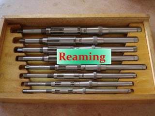
![IFS-2011
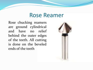
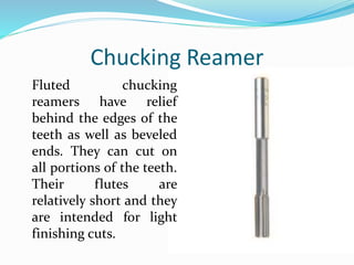
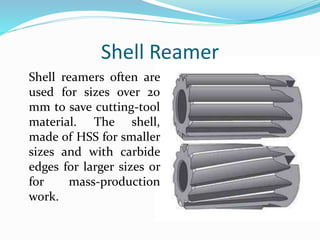
What is the main difference between rose reamer
and chucking reamer ? Write in short about shell
reamer.
[5-marks]](https://image.slidesharecdn.com/ch-6reamingboringbroaching-170423125016/85/Ch-6-reaming-boring-broaching-13-320.jpg)

![IAS-2009 Main
Define the term ‘ rose reamer’ . [2-Marks]](https://image.slidesharecdn.com/ch-6reamingboringbroaching-170423125016/85/Ch-6-reaming-boring-broaching-26-320.jpg)
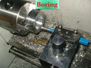
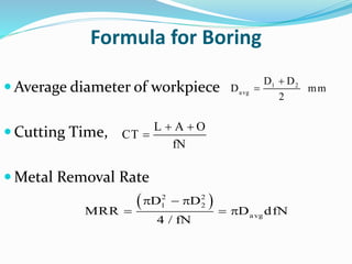

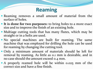
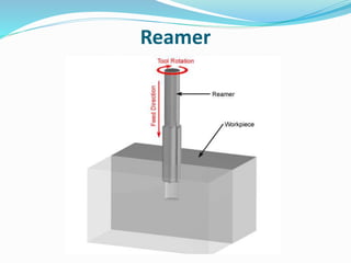
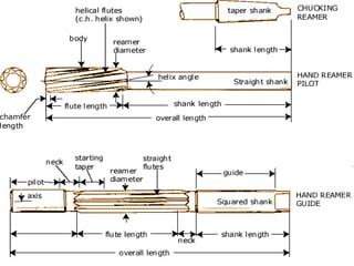
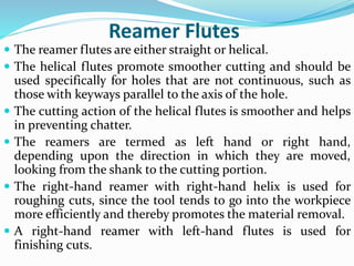
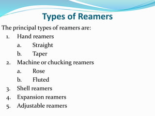
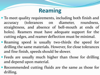
1. Reaming is a machining process that removes a small amount of material from the surface of holes to bring them to a more exact size and improve surface finish. It uses multi-flute cutting tools with straight or helical flutes. 2. There are different types of reamers including hand, machine, shell, expansion, and adjustable reamers. Rose reamers cut only on the beveled ends of teeth while chucking reamers can cut on all portions of teeth. 3. Boring is used to enlarge existing holes and make them concentric to the axis of rotation. It is essentially internal turning where the tool feeds parallel to the workpiece rotation axis. Boring


