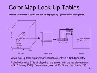
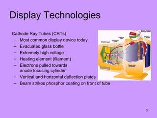
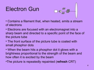
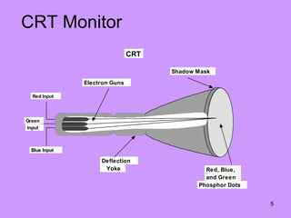
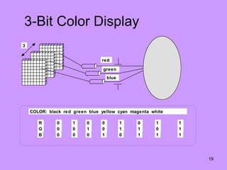
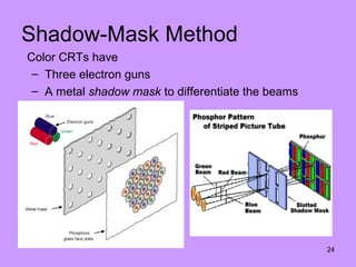
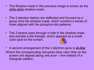
3. 3
Display Technologies
Cathode Ray Tubes (CRTs)
– Most common display device today
– Evacuated glass bottle
– Extremely high voltage
– Heating element (filament)
– Electrons pulled towards
anode focusing cylinder
– Vertical and horizontal deflection plates
– Beam strikes phosphor coating on front of tube
4. 4
Electron Gun
• Contains a filament that, when heated, emits a stream
of electrons
• Electrons are focused with an electromagnet into a
sharp beam and directed to a specific point of the face of
the picture tube
• The front surface of the picture tube is coated with
small phosphor dots
• When the beam hits a phosphor dot it glows with a
brightness proportional to the strength of the beam and
how often it is excited by the beam
•The picture is repeatedly repainted (refresh CRT)
5. 5
CRT Monitor
Electron Guns
Red Input
Green
Input
Blue Input
Deflection
Yoke
Shadow Mask
Red, Blue,
and Green
Phosphor Dots
CRT
6. 6
List the properties of CRT
1. Persistence
2. Resolution
3. Addressability
4. Aspect ratio
7. 7
Persistence
How long small spots continue to emit light after the
beam is moved. How long it takes for the emitted light
from the screen to decay to one-tenth of its original
intensity.
– Lower persistence requires high refresh rate & it is
good for animation.
– High persistence is useful for displaying highly
complex static pictures.
– Graphics monitors are usually constructed with 10 to
60 microseconds.
8. 8
Resolution
• The maximum number of points that can be displayed
without an overlap on a CRT is referred to as the resolution.
• The smaller the spot size, the higher the resolution.
• The higher the resolution, the better is the graphics system
• High quality resolution is 1280x1024
• The intensity distribution of spots on the screen have
Gaussian shape.
• Adjacent points will appear distinct as long as their
separation is greater than the diameter at which each spot
has intensity of about 60% of that at the center of the spot.
Intensity distribution
9. 9
Addressability
• Addressability is the number of individual dots
per inch (d.p.i.) that can be created. If the
address of the current dot is (x, y) then the next
dot will be (x + y), (x + y + 1)
• The picture on a screen consists of intensified
points.
• The smallest addressable point on the screen
is called pixel or picture element
10. 10
Aspect ratio
This number gives the ratio between vertical points and
horizontal points necessary to produce equal length lines
in both directions on the screen. Aspect ratio = Âľ means
that a vertical line plotted with 3 points is equal in length
to a horizontal line plotted with 4 points.
13. 13
Raster Scan Displays (1)
– Raster: A rectangular array of points or dots
– Pixel: One dot or picture element of the raster. Its
intensity range for pixels depends on capability of the
system
– Scan line: A row of pixels
– Picture elements are stored in a memory called frame
buffer
14. 14
Raster Scan Displays (2)
– Frame must be “refreshed” to draw new images
– As new pixels are struck by electron beam, others
are decaying
– Electron beam must hit all pixels frequently to
eliminate flicker
– Critical fusion frequency
• Typically 60 times/sec
15. 15
Raster Scan Displays (3)
– Intensity of pixels depends on the system for
example black and white screens each point can
be on or off thus it needs one bit of memory to
represent each pixel.
– To paint color screen additional bits are needed.
If three bits are used, then number of different
colors are 2*2*2.
– A special memory is used to store the image with
scan-out synchronous to the raster. We call this
the frame buffer.
17. 17
Frame
Buffers
• A frame buffer may be thought of as computer memory
organized as a two-dimensional array with each (x,y)
addressable location corresponding to one pixel.
• Bit Planes or Bit Depth is the number of bits corresponding to
each pixel.
• A typical frame buffer resolution might be
– 640 x 480 x 8
– 1280 x 1024 x 8
– 1280 x 1024 x 24
20. 20
True Color Display
24 bit planes, 8 bits per color gun.
224
= 16,777,216
Green
Red
Blue
N
N
N
21. 21
Color Map Look-Up Tables
Extends the number of colors that can be displayed by a given number of bit-planes.
0
1
0
0
0
0
1
1
67
100110100001
0
67
255
1001 1010 0001
R G B
RED
GREEN
BLUE
Pixel displayed
at x', y'
Pixel in
bit map
at x', y'
0 x
0
y
x
max
max
y
Bit map Look-up table Display
Video look-up table organization: each table entry is a 12 bit per entry.
A pixel with value 67 is displayed on the screen with the red electron gun
at 9/15 (binary 1001) of maximum, green at 10/15, and the blue is 1/15.
22. 2 Basic Techniques for Color Display
Beam-Penetration
Method
Shadow-Mask
Method
23. 23
Beam-Penetration Method
• Used with random scan monitors
• The screen has two layers of phosphor: usually red
and green
• The displayed color depends on how far the electron
beam penetrates through the two layers.
• A beam of slow electrons excites only the outer of the
red layer, a beam of fast electrons penetrates through
the red layer and excites the inner green layer, and at
intermediate beam speeds, combinations of the two
colors are emitted to show other colors (yellow &
orange)
25. • The Shadow mask in the previous image is known as the
delta-delta shadow-mask.
• The 3 electron beams are deflected and focused as a
group onto the shadow mask, which contains a series of
holes aligned with the phosphor-dot patterns.
• The 3 beams pass through a hole in the shadow mask
and activate a dot triangle, which appears as a small
color spot on the screen.
• A second arrangement of the 3 electron guns is in-line
Where the corresponding red-green-blue color dots on the
screen are aligned along one scan – line instead of a
triangular pattern.
26. Controlling Colors in shadow mask
• Different colors can be obtained by varying the intensity levels of the
three electron beams.
• Example: Simply turning off the red and green guns, we get only the
color coming from the blue phosphor.
• Yellow = Green + Red
• Magenta = Blue + Red
• Cyan = Blue + Green
• White is produced when all the 3 guns possess equal amount of
intensity.
27. Application:
• Color CRT’s in graphics systems are designed as RGB
monitors, which employ the shadow mask technique.
• The color CRT takes the intensity level for each electron
gun ( red, green and blue) directly from the computer
system without any intermediate processing.
• An RGB color system with 24 bits of storage per pixel is
generally referred to as full-color system or a true-
color system. It allows 256 voltage settings for each
electron gun and nearly 17 million colors.
28. 28
Display Processor
• Also called either a Graphics Controller or Display
CoProcessor
• Specialized hardware to assist in scan converting
output primitives into the frame buffer.
• Fundamental difference among display systems is how
much the display processor does versus how much
must be done by the graphics subroutine package
executing on the general-purpose CPU.
29. 29
Video
ControllerCycles through the frame buffer, one scan line at a time. Contents of the memory are
used the control the CRT's beam intensity or color.
X address
Y address
Pixel
value(s)
Raster scan
generator
Data
Horizontal
and vertical
deflection
signals
Intensity
or color
Linear
address
Set or increment
Set or decrement
M
e
m
o
r
y
31. 31
Input
Devices
• Locator Devices:
– to indicate a position and/or orientation
– to select a displayed entity
– Tablet, Mouse, Trackball, Joystick, Touch Panel, Light Pen
• Keyboard devices:
– to input a character string
– Alphanumeric keyboard (coded - get single ASCII character,
unencoded - get state of all keys - more flexible)
• Valuator Devices:
– to input a single value in the space of real numbers
– Rotary dials (Bounded or Unbounded), Linear sliders
• Choice Devices:
– to select from a set of possible actions or choices
– Function keys
Editor's Notes
Addressability is a measure of the spacing between the centers of vertical and horizontal lines.
In graphics mode there are 800x600