Downloaded 50 times


![ISOMETRIC VIEW ISOMETRIC PROJECTION
H H
TYPES OF ISOMETRIC DRAWINGS
Drawn by using Isometric scale
( Reduced dimensions )
Drawn by using True scale
( True dimensions )
450
300
0
1
2
3
4
0
1
2
3
4
Isometric scale [ Line AC ]
required for Isometric Projection
A B
C
D
CONSTRUCTION OF ISOM.SCALE.
From point A, with line AB draw 300 and
450 inclined lines AC & AD resp on AD.
Mark divisions of true length and from
each division-point draw vertical lines
upto AC line.
The divisions thus obtained on AC
give lengths on isometric scale.](https://image.slidesharecdn.com/engineeringgraphics-isometric-140417065413-phpapp01/85/Engineering-graphics-isometric-4-320.jpg)
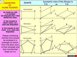
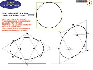
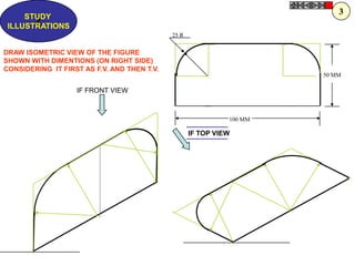
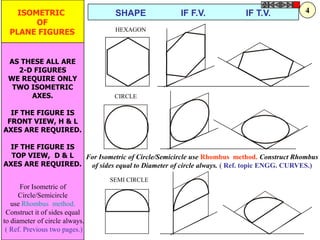
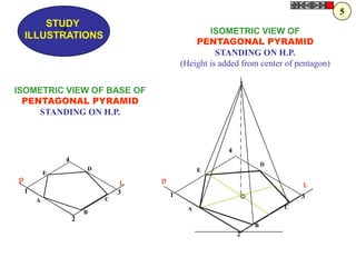
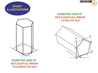
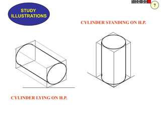
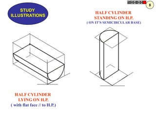
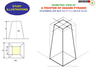
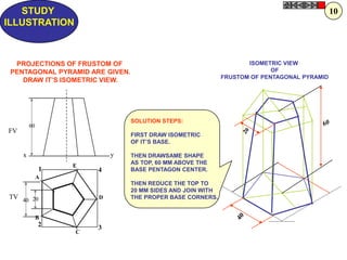
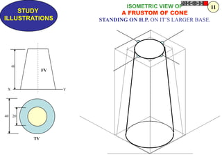
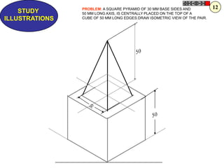
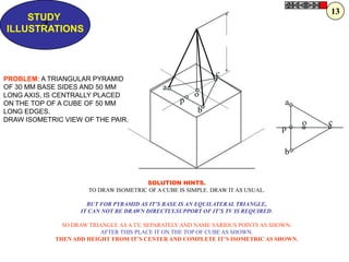
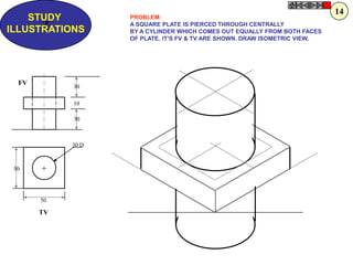
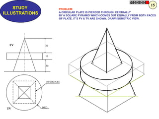
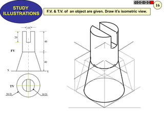
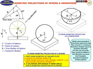
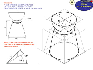
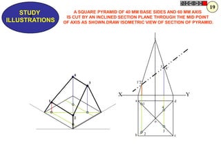
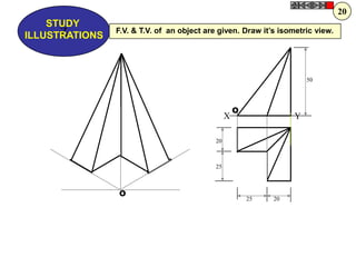
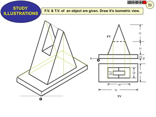
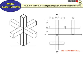
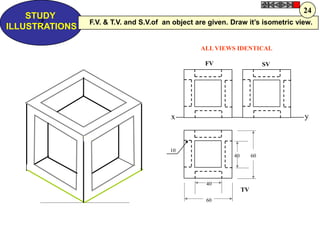
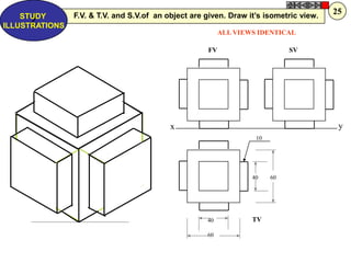
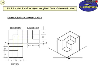
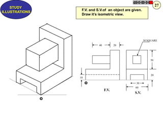
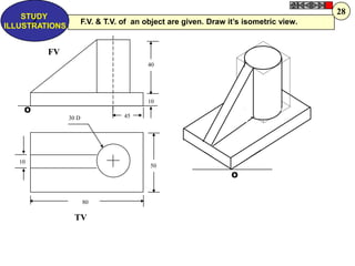
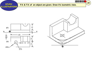
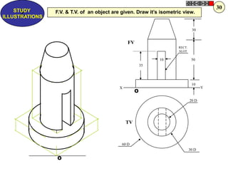
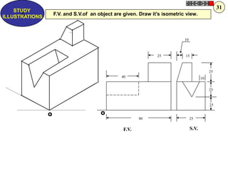
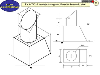
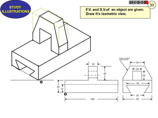
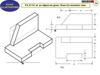
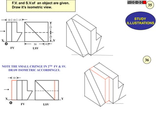
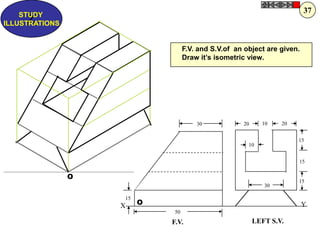
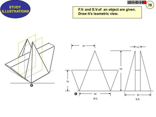

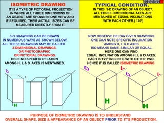
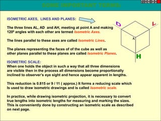
This document provides information about isometric drawings and projections. It begins with an introduction to 3D drawings and defines isometric drawings as having specific equal inclinations between height, length, and depth axes. Several examples of isometric views of objects like prisms, pyramids, and cylinders are shown. The document also discusses isometric scales, axes, lines, and planes. It concludes with examples of how to draw isometric views when given front, top, or side views of objects.


