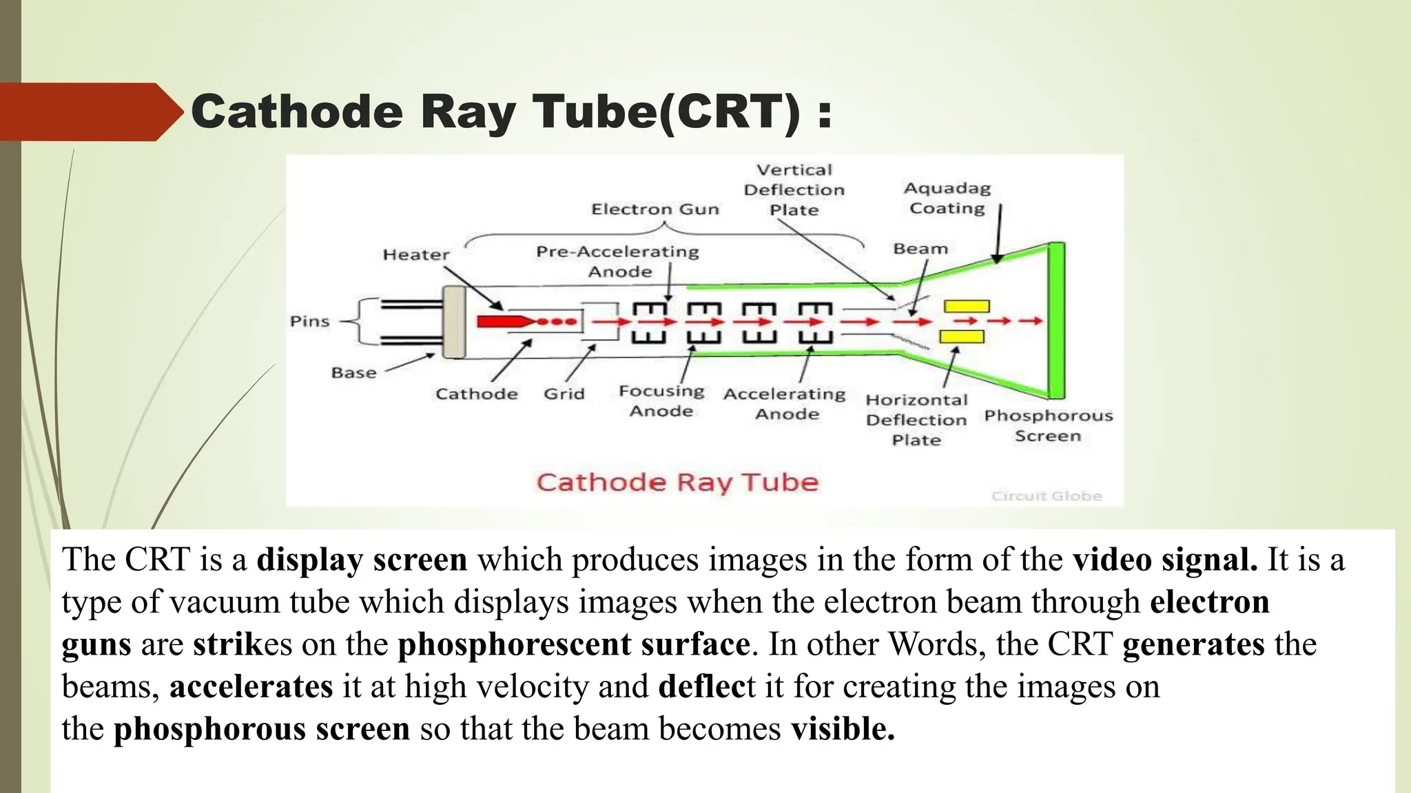
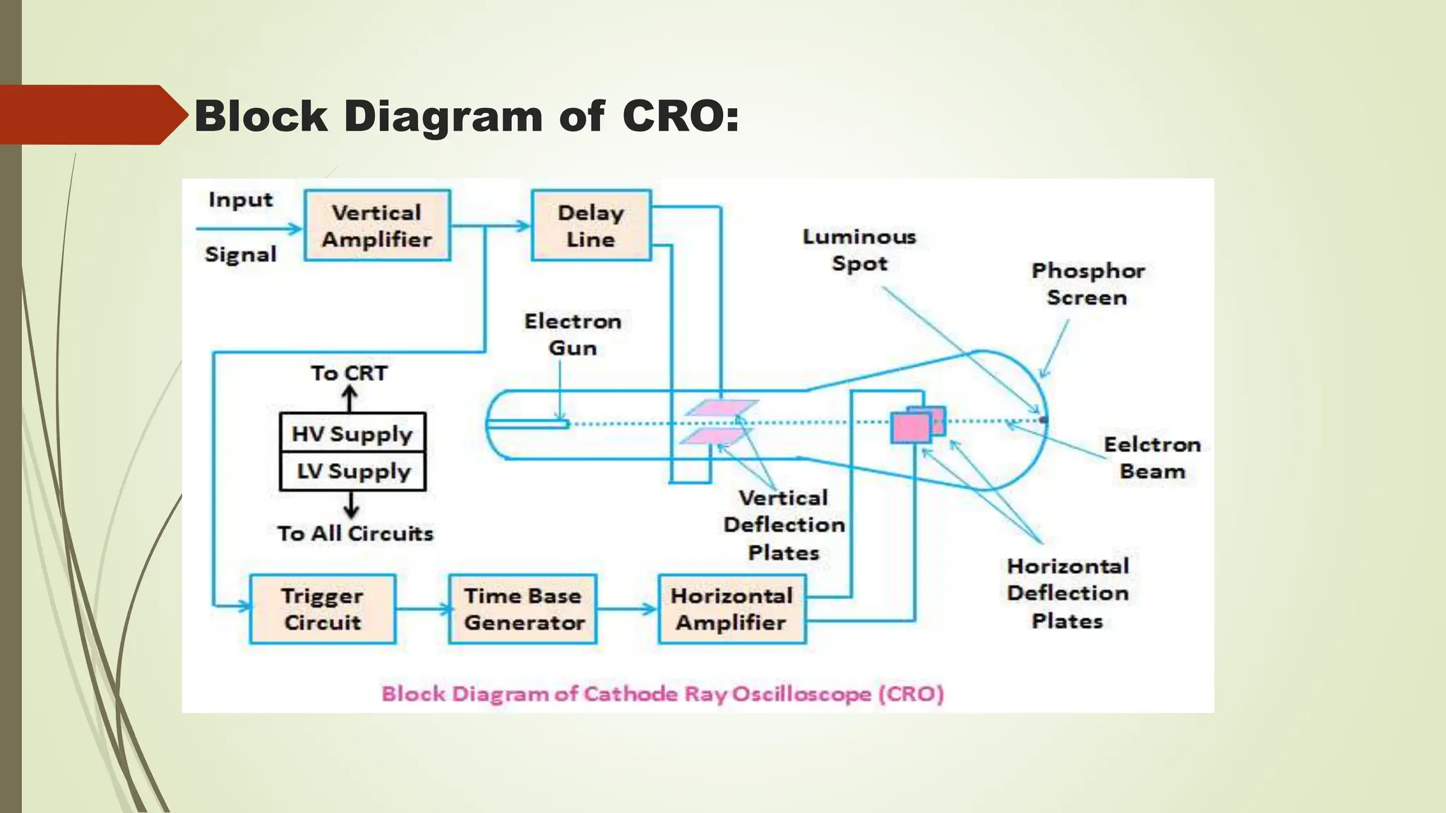
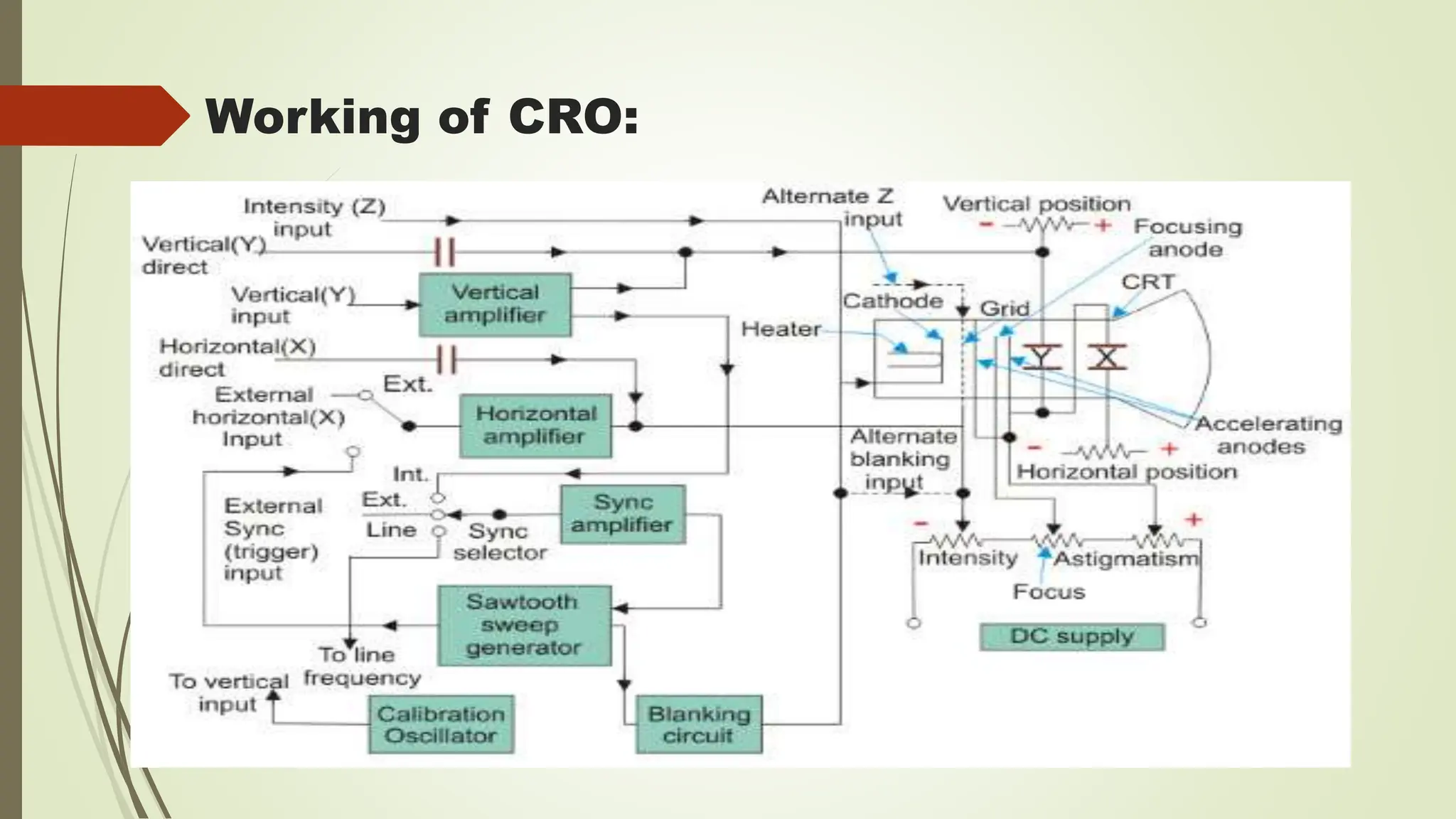
Cathode Ray Oscilloscope
Introduction :
 The CRO stands for a cathode ray oscilloscope. It is typically divided into four
sections which are display, vertical controllers, horizontal controllers, and Triggers.
Most of the oscilloscopes are used the probes and they are used for the input of any
instrument. We can analyse the waveform by plotting amplitude along with the x-axis
and y-axis. The applications of CRO’s mainly involve in the radio, TV receivers, also
in laboratory work involving research and design. In modern electronics, the CRO
plays an important role in the electronic circuits.
 The CRO depends on the movement of an electron beam ,which is bombarded on the
screen coated with the fluorescent screen material, to produce visible spot . If the
electron beam is deflected on the both conventional axis, i.e. X-axis and Y-axis ,a two
dimensional display is produced .
What is CRO?
 The cathode ray oscilloscope is an electronic test instrument, it is used to obtain
waveforms when the different input signals are given. In the early days, it is called as
an Oscillograph. The oscilloscope observes the changes in the electrical signals over
time, thus the voltage and time describe a shape and it is continuously graphed beside
a scale. By seeing the waveform, we can analyse some properties like amplitude,
frequency, rise time, distortion, time interval and etc..
 The Oscilloscope is basically an electron beam voltmeter. The heart of the
oscilloscope is the Cathode Ray Tube (CRT) which makes the applied signal visible
by the deflection of the thin beam of electrons .Since the electron has pratically no
weight ,and hence no inertia, therefore the beam of electrons can be moved to follow
waveforms varying at a rate of millions of time/second. Thus, the electron beam
faithfully follows rapid variations in Signal voltage and traces a visible path on the
CRT screen.
Cathode Ray Tube(CRT) :
The CRT is a display screen which produces images in the form of the video signal. It is a
type of vacuum tube which displays images when the electron beam through electron
guns are strikes on the phosphorescent surface. In other Words, the CRT generates the
beams, accelerates it at high velocity and deflect it for creating the images on
the phosphorous screen so that the beam becomes visible.
Working of CRT:
 The working of CRT depends on the movement of electrons beams. The electron guns
generate sharply focused electrons which are accelerated at high voltage. This high-
velocity electron beam when strikes on the fluorescent screen creates luminous spot.
 After exiting from the electron gun, the beam passes through the pairs of electrostatic
deflection plate. These plates deflected the beams when the voltage applied across it.
The one pair of plate moves the beam upward and the second pair of plate moves the
beam from one side to another. The horizontal and vertical movement of the electron
are independent of each other, and hence the electron beam positioned anywhere on
the screen.
 The working parts of a CRT are enclosed in a vacuum glass envelope so that the
emitted electron can easily move freely from one end of the tube to the other.
CRT Features:
Size : size refers to the screen diameter. CRTs for oscilloscopes are available in the in
sizes of 1,2,3,5, and 7 inches. 3 inches is the most common for the portable instruments.
For example a CRT having a number of 5GP1. The first number 5 indicates that it is
5inch tube .Both round and rectangle CRTs are found in the scopes today. The vertical
viewing size is 8cm and horizontal is 10 cm.
 Phosphor : The screen is coated with a fluorescent material called phosphor. The trace
colors in the electrostatic CRTs for oscilloscope are blue , green and blue green. White is
used for in the TVS, and blue-white , Orange and yellow are used for radar.
 The phosphor of the oscilloscope is designed as P1- Green Medium,P2 – Blue green
Medium, P5 – Blue very short and P11 – Blue short.
 Operating Voltages : The CRT requires a heater of 6.3 volts ac or dc at 600 mA.
 Several dc voltages are listed below. The voltages vary with the type of tube used.
 1. Negative grid voltage -14v to -200v.
 2. Positive anode no.1(focusing anode ) -100v to -1100v.
 3. Positive anode no.2(accelerating anode ) -600v to -6000v
 4. Positive anode no.3(accelerating anode ) 200v to 20000v in some cases.
 Deflection voltages : Either ac or dc voltage will deflect the beam. The distance
through which the spot moves on the screen is proportional to the dc, or peak ac
amplitude . The deflection sensitivity of the tube is usually stated as dc voltage(peak ac
voltage) required for each cm of deflection of the spot on the screen.
 Viewing screen : Rectangle glass plate coated with phosphor material. 8cm x 10cm
Block Diagram of CRO:
 The following block diagram shows the general purpose CRO contraction. The CRO
recruit the cathode ray tube and acts as a heat of the oscilloscope. In an oscilloscope, the
CRT produces the electron beam which is accelerated to a high velocity and brings to the
focal point on a fluorescent screen. Thus, the screen produces a visible spot where the
electron beam strikes with it. By detecting the beam above the screen in reply to the
electrical signal, the electrons can act as an electrical pencil of light which produces a light
where it strikes.
 If the electron beam is detected in the X-axis and the Y- axis a trigger To complete
this task we need various electrical signals and voltages. This provides the power
supply circuit of the oscilloscope. Here we will use high voltage and low voltage.
The low voltage is used for the heater of the electron gun to generate the electron
beam. The high voltage is required for the cathode ray tube to speed up the beam.
The normal voltage supply is necessary for other control units of the oscilloscope.
Block diagram Explanation :
 The horizontal and vertical plates are placed between the electron gun and the
screen, thus it can detect the beam according to the input signal. Just before
detecting the electron beam on the screen in the horizontal direction which is in X-
axis a constant time-dependent rate, a time base generator is given by the oscillator.
The signals are passed from the vertical deflection plate through the vertical
amplifier. Thus, it can amplify the signal to a level will be provided the deflection of
the circuit is given for the synchronizing these two types detections. Hence the
horizontal deflection starts at the same point of the input signal.
Working of CRO:
basic circuit of a cathode ray oscilloscope. In this, we will discuss
important parts of the oscilloscope.
 Vertical Deflection System
 The main function of this amplifier is to amplify the weak signal so that the amplified
signal can produce the desired signal. To examine the input signals are penetrated to
the vertical deflection plates through the input attenuator and number of amplifier
stages.
 Horizontal Deflection System
 The vertical and horizontal system consists of horizontal amplifiers to amplify the
weak input signals, but it is different to the vertical deflection system. The horizontal
deflection plates are penetrated by a sweep voltage that gives a time base. By seeing
the circuit diagram the sawtooth sweep generator is triggered by the synchronizing
amplifier while the sweep selector switches in the internal position. So the trigger saw
tooth generator gives the input to the horizontal amplifier by following the
mechanism.Here we will discuss the four types of sweeps.
 Recurrent Sweep
 As the name, itself says that the saw tooth is respective that is a new sweep is started
immodestly at the end of the previous sweep.
 Triggered Sweep
 Sometimes the waveform should be observed that it may not be predicted, thus the desired
that the sweep circuit remains inoperative and the sweep should be initiated by the
waveform under the examination. In these cases, we will use the triggered sweep.
 Driven Sweep
 In general, the drive sweep is used when the sweep is a free running but it is a triggered by
the signal under the test.
 Non-Saw Tooth Sweep
 This sweep is used to find the difference between the two voltages. By using the non-
sawtooth sweep we can compare the frequency of the input voltages.
 Synchronization
 The synchronization is done to produce the stationary pattern. The synchronization is
between the sweep and the signal should measure. There are some sources of
synchronization which can be selected by the synchronization selector. Which are
discussed below.
 Internal
 In this the signal is measured by the vertical amplifier and the trigger is abstained by
the signal.
 External
 In the external trigger, the external trigger should be present.
 Line
 The line trigger is produced by the power supply.
 Intensity Modulation
 This modulation is produced by inserting the signal between the ground and cathode.
This modulation causes by brightening the display.
 Positioning Control
 By applying the small independent internal direct voltage source to the detecting
plates through the potentiometer the position can be controlled and also we can
control the position of the signal.
 Intensity Control
 The intensity has a difference by changing the grid potential with respect to the cathode.
Applications of CRO:
Voltage measurement
Current measurement
Examination of waveform
Measurement of phase and frequency
Uses of CRO:
In laboratory, the CRO can be used as
It can display different types of waveforms
It can measure short time interval
In voltmeter, it can measure potential difference
Thank you

Cathode ray oscilloscope bsc notes vi sem

  • 1.
  • 2.
    Introduction :  TheCRO stands for a cathode ray oscilloscope. It is typically divided into four sections which are display, vertical controllers, horizontal controllers, and Triggers. Most of the oscilloscopes are used the probes and they are used for the input of any instrument. We can analyse the waveform by plotting amplitude along with the x-axis and y-axis. The applications of CRO’s mainly involve in the radio, TV receivers, also in laboratory work involving research and design. In modern electronics, the CRO plays an important role in the electronic circuits.  The CRO depends on the movement of an electron beam ,which is bombarded on the screen coated with the fluorescent screen material, to produce visible spot . If the electron beam is deflected on the both conventional axis, i.e. X-axis and Y-axis ,a two dimensional display is produced .
  • 3.
    What is CRO? The cathode ray oscilloscope is an electronic test instrument, it is used to obtain waveforms when the different input signals are given. In the early days, it is called as an Oscillograph. The oscilloscope observes the changes in the electrical signals over time, thus the voltage and time describe a shape and it is continuously graphed beside a scale. By seeing the waveform, we can analyse some properties like amplitude, frequency, rise time, distortion, time interval and etc..  The Oscilloscope is basically an electron beam voltmeter. The heart of the oscilloscope is the Cathode Ray Tube (CRT) which makes the applied signal visible by the deflection of the thin beam of electrons .Since the electron has pratically no weight ,and hence no inertia, therefore the beam of electrons can be moved to follow waveforms varying at a rate of millions of time/second. Thus, the electron beam faithfully follows rapid variations in Signal voltage and traces a visible path on the CRT screen.
  • 4.
    Cathode Ray Tube(CRT): The CRT is a display screen which produces images in the form of the video signal. It is a type of vacuum tube which displays images when the electron beam through electron guns are strikes on the phosphorescent surface. In other Words, the CRT generates the beams, accelerates it at high velocity and deflect it for creating the images on the phosphorous screen so that the beam becomes visible.
  • 5.
    Working of CRT: The working of CRT depends on the movement of electrons beams. The electron guns generate sharply focused electrons which are accelerated at high voltage. This high- velocity electron beam when strikes on the fluorescent screen creates luminous spot.  After exiting from the electron gun, the beam passes through the pairs of electrostatic deflection plate. These plates deflected the beams when the voltage applied across it. The one pair of plate moves the beam upward and the second pair of plate moves the beam from one side to another. The horizontal and vertical movement of the electron are independent of each other, and hence the electron beam positioned anywhere on the screen.  The working parts of a CRT are enclosed in a vacuum glass envelope so that the emitted electron can easily move freely from one end of the tube to the other.
  • 6.
    CRT Features: Size :size refers to the screen diameter. CRTs for oscilloscopes are available in the in sizes of 1,2,3,5, and 7 inches. 3 inches is the most common for the portable instruments. For example a CRT having a number of 5GP1. The first number 5 indicates that it is 5inch tube .Both round and rectangle CRTs are found in the scopes today. The vertical viewing size is 8cm and horizontal is 10 cm.  Phosphor : The screen is coated with a fluorescent material called phosphor. The trace colors in the electrostatic CRTs for oscilloscope are blue , green and blue green. White is used for in the TVS, and blue-white , Orange and yellow are used for radar.  The phosphor of the oscilloscope is designed as P1- Green Medium,P2 – Blue green Medium, P5 – Blue very short and P11 – Blue short.
  • 7.
     Operating Voltages: The CRT requires a heater of 6.3 volts ac or dc at 600 mA.  Several dc voltages are listed below. The voltages vary with the type of tube used.  1. Negative grid voltage -14v to -200v.  2. Positive anode no.1(focusing anode ) -100v to -1100v.  3. Positive anode no.2(accelerating anode ) -600v to -6000v  4. Positive anode no.3(accelerating anode ) 200v to 20000v in some cases.  Deflection voltages : Either ac or dc voltage will deflect the beam. The distance through which the spot moves on the screen is proportional to the dc, or peak ac amplitude . The deflection sensitivity of the tube is usually stated as dc voltage(peak ac voltage) required for each cm of deflection of the spot on the screen.  Viewing screen : Rectangle glass plate coated with phosphor material. 8cm x 10cm
  • 8.
  • 9.
     The followingblock diagram shows the general purpose CRO contraction. The CRO recruit the cathode ray tube and acts as a heat of the oscilloscope. In an oscilloscope, the CRT produces the electron beam which is accelerated to a high velocity and brings to the focal point on a fluorescent screen. Thus, the screen produces a visible spot where the electron beam strikes with it. By detecting the beam above the screen in reply to the electrical signal, the electrons can act as an electrical pencil of light which produces a light where it strikes.  If the electron beam is detected in the X-axis and the Y- axis a trigger To complete this task we need various electrical signals and voltages. This provides the power supply circuit of the oscilloscope. Here we will use high voltage and low voltage. The low voltage is used for the heater of the electron gun to generate the electron beam. The high voltage is required for the cathode ray tube to speed up the beam. The normal voltage supply is necessary for other control units of the oscilloscope. Block diagram Explanation :
  • 10.
     The horizontaland vertical plates are placed between the electron gun and the screen, thus it can detect the beam according to the input signal. Just before detecting the electron beam on the screen in the horizontal direction which is in X- axis a constant time-dependent rate, a time base generator is given by the oscillator. The signals are passed from the vertical deflection plate through the vertical amplifier. Thus, it can amplify the signal to a level will be provided the deflection of the circuit is given for the synchronizing these two types detections. Hence the horizontal deflection starts at the same point of the input signal.
  • 11.
  • 12.
    basic circuit ofa cathode ray oscilloscope. In this, we will discuss important parts of the oscilloscope.  Vertical Deflection System  The main function of this amplifier is to amplify the weak signal so that the amplified signal can produce the desired signal. To examine the input signals are penetrated to the vertical deflection plates through the input attenuator and number of amplifier stages.  Horizontal Deflection System  The vertical and horizontal system consists of horizontal amplifiers to amplify the weak input signals, but it is different to the vertical deflection system. The horizontal deflection plates are penetrated by a sweep voltage that gives a time base. By seeing the circuit diagram the sawtooth sweep generator is triggered by the synchronizing amplifier while the sweep selector switches in the internal position. So the trigger saw tooth generator gives the input to the horizontal amplifier by following the mechanism.Here we will discuss the four types of sweeps.
  • 13.
     Recurrent Sweep As the name, itself says that the saw tooth is respective that is a new sweep is started immodestly at the end of the previous sweep.  Triggered Sweep  Sometimes the waveform should be observed that it may not be predicted, thus the desired that the sweep circuit remains inoperative and the sweep should be initiated by the waveform under the examination. In these cases, we will use the triggered sweep.  Driven Sweep  In general, the drive sweep is used when the sweep is a free running but it is a triggered by the signal under the test.
  • 14.
     Non-Saw ToothSweep  This sweep is used to find the difference between the two voltages. By using the non- sawtooth sweep we can compare the frequency of the input voltages.  Synchronization  The synchronization is done to produce the stationary pattern. The synchronization is between the sweep and the signal should measure. There are some sources of synchronization which can be selected by the synchronization selector. Which are discussed below.  Internal  In this the signal is measured by the vertical amplifier and the trigger is abstained by the signal.
  • 15.
     External  Inthe external trigger, the external trigger should be present.  Line  The line trigger is produced by the power supply.  Intensity Modulation  This modulation is produced by inserting the signal between the ground and cathode. This modulation causes by brightening the display.  Positioning Control  By applying the small independent internal direct voltage source to the detecting plates through the potentiometer the position can be controlled and also we can control the position of the signal.
  • 16.
     Intensity Control The intensity has a difference by changing the grid potential with respect to the cathode.
  • 17.
    Applications of CRO: Voltagemeasurement Current measurement Examination of waveform Measurement of phase and frequency
  • 18.
    Uses of CRO: Inlaboratory, the CRO can be used as It can display different types of waveforms It can measure short time interval In voltmeter, it can measure potential difference
  • 19.