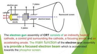
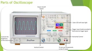
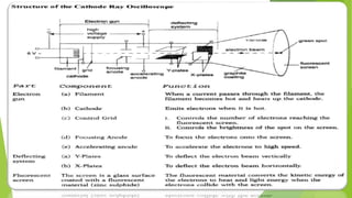
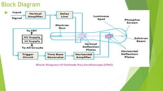
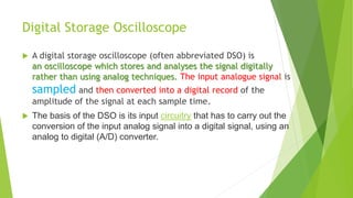
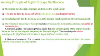
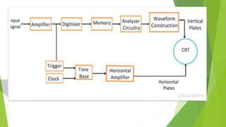
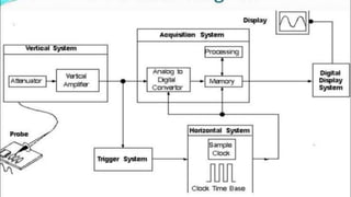
General Purpose CRO
Waqar Ali Bhatti (K-18ES35)
Ayaz Gul Hingorjo (k-18es21)
Abdul Qayoom Mangrio (k-18es31)
 The Cathode-ray-Oscilloscope (CRO) is a common laboratory
instruments that provides;
 1-Accurate time & amplitude
 2-Measurements of voltage signals over a wide range of frequencies.
Its reliability, Stability, and ease of operation make it suitable as a
general purpose laboratory instrument. The heart of the CRO is a
cathode-ray tube shown in figure
By watching This Animated
video you will understand
easily…!
The electron gun assembly of CRT consists of an indirectly heated
cathode, a control grid surrounding the cathode, a focusing anode and an
accelerating anode. The main function of the electron gun assembly
is to provide a focused electron beam which is accelerated
towards the phosphor screen.
Parts of Oscilloscope
 A basic oscilloscope consists of three different systems
 the vertical system, horizontal system, and trigger system.
 Each system contributes to the oscilloscope's ability to accurately reconstruct a signal.
 The front panel of an oscilloscope is divided into three sections labeled
 i-Vertical ii- Horizontal iii-Trigger.
Control of Oscilloscope
 The control available on most oscilloscopes provides a wide range of operating condition and this make
the instrument specially versatile.
Many of these controls are common to most oscilloscope; a brief description below;
 Power ans Scale Illumination control: Turns instrument on and controls illumination.
 Focus control: Focus the spot or trace on the screen.
 Intensity control: Regulates the brightness of the spot or trace.
 front-panel controls of oscilloscope are divided into four main
groups — the horizontal and vertical controls, input controls and
the triggering controls.
 the horizontal controls of the oscilloscope allow users to adjust
the display’s horizontal scale. This section includes the control for the
horizontal delay (offset) as well as the control that indicates the time
per division on the x-axis.
 the oscilloscope’s vertical controls are generally located in a section
specifically marked Vertical. The controls found in this section allow
users to adjust the display’s vertical aspect, and include the control
that indicates the number of volts per division on the display grid’s y-
axis.
 The trigger controls of the oscilloscope allow users to choose the
vertical trigger level as well as the desired triggering capability.
Common triggering types include glitch triggering, edge triggering and
pulse-width triggering.
Advantages & Usage
 Applications of CRO
 Voltage measurement
 Current measurement
 Examination of waveform
 Measurement of phase and frequency
 Uses of CRO
 In laboratory, the CRO can be used as
 It can display different types of waveforms
 It can measure short time interval
 In voltmeter, it can measure potential difference
Block Diagram
 The following block diagram shows the general purpose CRO
contraction. The CRO recruit the cathode ray tube and acts
as a heat of the oscilloscope. In an oscilloscope, the CRT
produces the electron beam which is accelerated to a high
velocity and brings to the focal point on a fluorescent
screen. Thus, the screen produces a visible spot where the
electron beam strikes with it. By detecting the beam above
the screen in reply to the electrical signal, the electrons can
act as an electrical pencil of light which produces a light
where it strikes.
Digital Storage Oscilloscope
 A digital storage oscilloscope (often abbreviated DSO) is
an oscilloscope which stores and analyses the signal digitally
rather than using analog techniques. The input analogue signal is
sampled and then converted into a digital record of the
amplitude of the signal at each sample time.
 The basis of the DSO is its input circuitry that has to carry out the
conversion of the input analog signal into a digital signal, using an
analog to digital (A/D) converter.
Working Principle of Digital Storage Oscilloscope
 The digital oscilloscope digitizes and stores the input signal
 This can be done by the use of CRT (Cathode ray tube) and digital memory.
 The digitization can be done by taking the sample input signals at periodic waveforms.
 The maximum frequency of the signal which is measured by the digital oscilloscope depends on
the two factors.
The sampling theory states that the sampling rate of the signal must be
twice as fast as the highest frequency of the input signal. The sampling rate means
analogue to digital converter has a high fast conversion rate.
: The converter uses the expensive flash whose resolution decreases
with the increases of a sampling rate.
Thank You.

Cathode Ray Oscilloscope CRO & Digital Oscilloscope 'S WORKING

  • 1.
    General Purpose CRO WaqarAli Bhatti (K-18ES35) Ayaz Gul Hingorjo (k-18es21) Abdul Qayoom Mangrio (k-18es31)
  • 2.
     The Cathode-ray-Oscilloscope(CRO) is a common laboratory instruments that provides;  1-Accurate time & amplitude  2-Measurements of voltage signals over a wide range of frequencies. Its reliability, Stability, and ease of operation make it suitable as a general purpose laboratory instrument. The heart of the CRO is a cathode-ray tube shown in figure
  • 3.
    By watching ThisAnimated video you will understand easily…!
  • 5.
    The electron gunassembly of CRT consists of an indirectly heated cathode, a control grid surrounding the cathode, a focusing anode and an accelerating anode. The main function of the electron gun assembly is to provide a focused electron beam which is accelerated towards the phosphor screen.
  • 6.
    Parts of Oscilloscope A basic oscilloscope consists of three different systems  the vertical system, horizontal system, and trigger system.  Each system contributes to the oscilloscope's ability to accurately reconstruct a signal.  The front panel of an oscilloscope is divided into three sections labeled  i-Vertical ii- Horizontal iii-Trigger.
  • 8.
    Control of Oscilloscope The control available on most oscilloscopes provides a wide range of operating condition and this make the instrument specially versatile. Many of these controls are common to most oscilloscope; a brief description below;  Power ans Scale Illumination control: Turns instrument on and controls illumination.  Focus control: Focus the spot or trace on the screen.  Intensity control: Regulates the brightness of the spot or trace.
  • 10.
     front-panel controlsof oscilloscope are divided into four main groups — the horizontal and vertical controls, input controls and the triggering controls.  the horizontal controls of the oscilloscope allow users to adjust the display’s horizontal scale. This section includes the control for the horizontal delay (offset) as well as the control that indicates the time per division on the x-axis.  the oscilloscope’s vertical controls are generally located in a section specifically marked Vertical. The controls found in this section allow users to adjust the display’s vertical aspect, and include the control that indicates the number of volts per division on the display grid’s y- axis.  The trigger controls of the oscilloscope allow users to choose the vertical trigger level as well as the desired triggering capability. Common triggering types include glitch triggering, edge triggering and pulse-width triggering.
  • 11.
    Advantages & Usage Applications of CRO  Voltage measurement  Current measurement  Examination of waveform  Measurement of phase and frequency  Uses of CRO  In laboratory, the CRO can be used as  It can display different types of waveforms  It can measure short time interval  In voltmeter, it can measure potential difference
  • 12.
    Block Diagram  Thefollowing block diagram shows the general purpose CRO contraction. The CRO recruit the cathode ray tube and acts as a heat of the oscilloscope. In an oscilloscope, the CRT produces the electron beam which is accelerated to a high velocity and brings to the focal point on a fluorescent screen. Thus, the screen produces a visible spot where the electron beam strikes with it. By detecting the beam above the screen in reply to the electrical signal, the electrons can act as an electrical pencil of light which produces a light where it strikes.
  • 13.
    Digital Storage Oscilloscope A digital storage oscilloscope (often abbreviated DSO) is an oscilloscope which stores and analyses the signal digitally rather than using analog techniques. The input analogue signal is sampled and then converted into a digital record of the amplitude of the signal at each sample time.  The basis of the DSO is its input circuitry that has to carry out the conversion of the input analog signal into a digital signal, using an analog to digital (A/D) converter.
  • 14.
    Working Principle ofDigital Storage Oscilloscope  The digital oscilloscope digitizes and stores the input signal  This can be done by the use of CRT (Cathode ray tube) and digital memory.  The digitization can be done by taking the sample input signals at periodic waveforms.  The maximum frequency of the signal which is measured by the digital oscilloscope depends on the two factors. The sampling theory states that the sampling rate of the signal must be twice as fast as the highest frequency of the input signal. The sampling rate means analogue to digital converter has a high fast conversion rate. : The converter uses the expensive flash whose resolution decreases with the increases of a sampling rate.
  • 17.