Download as PDF, PPTX


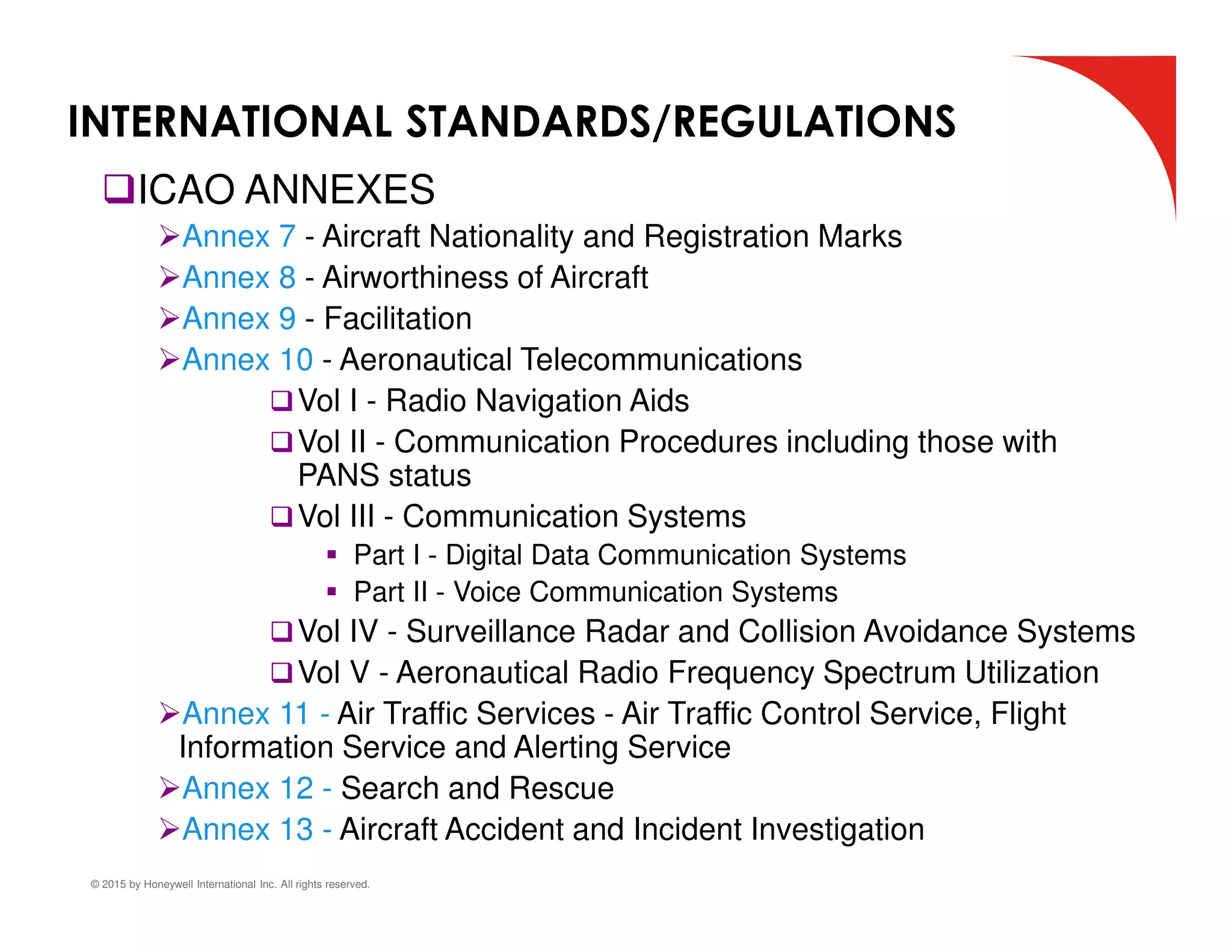


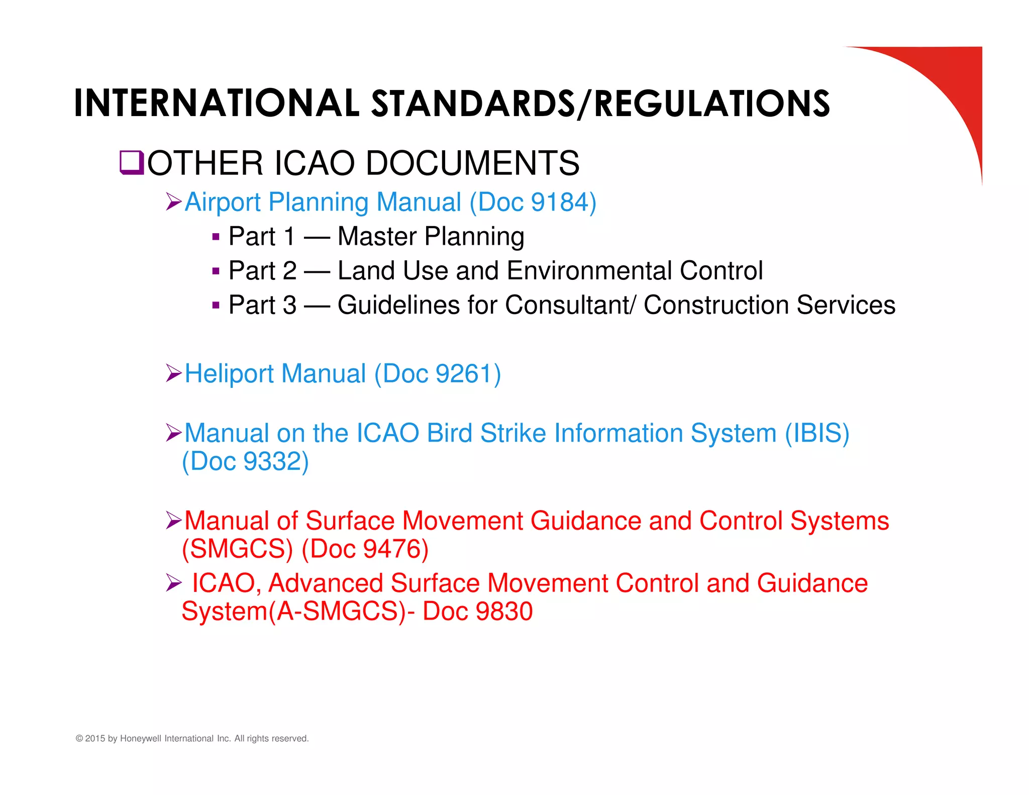
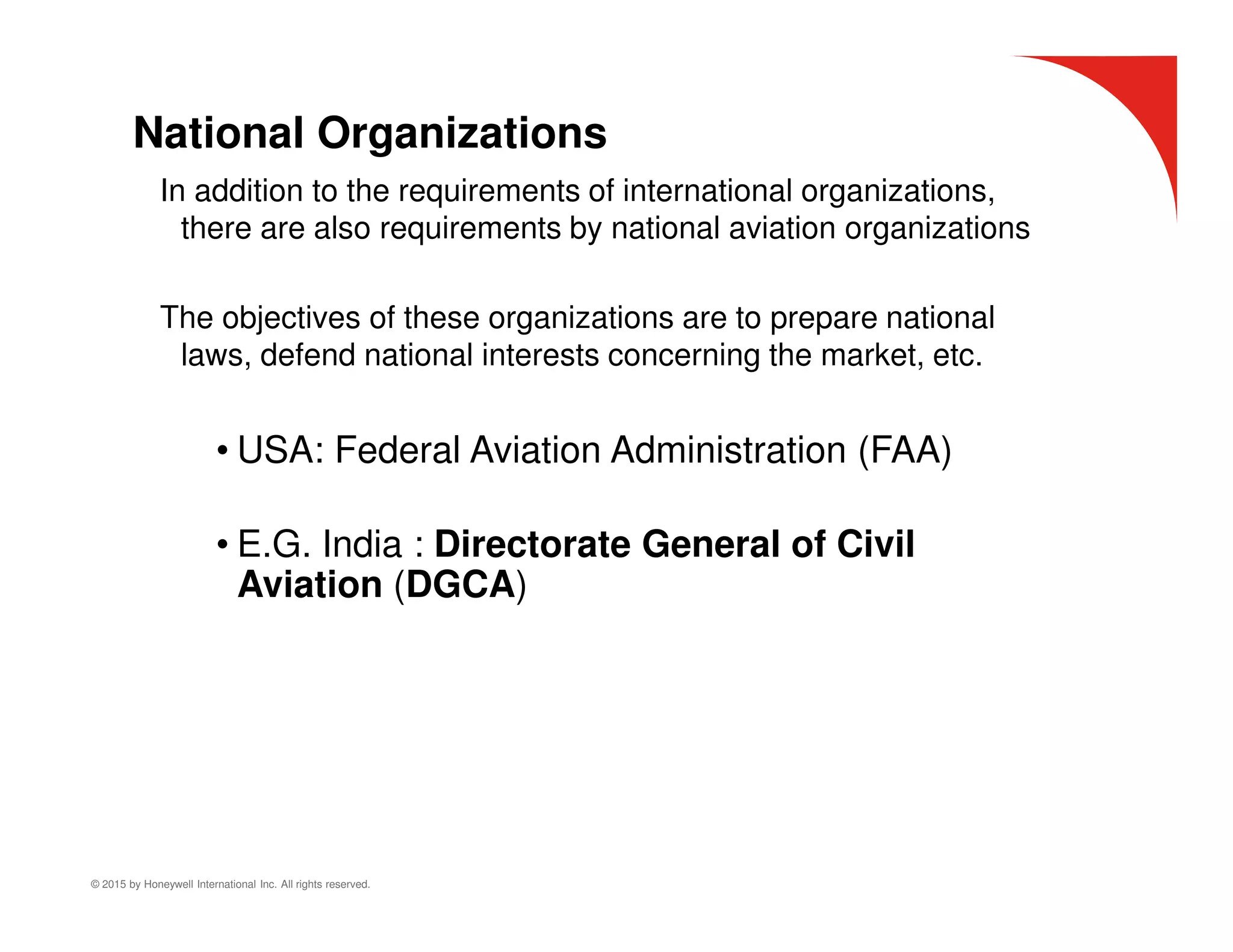


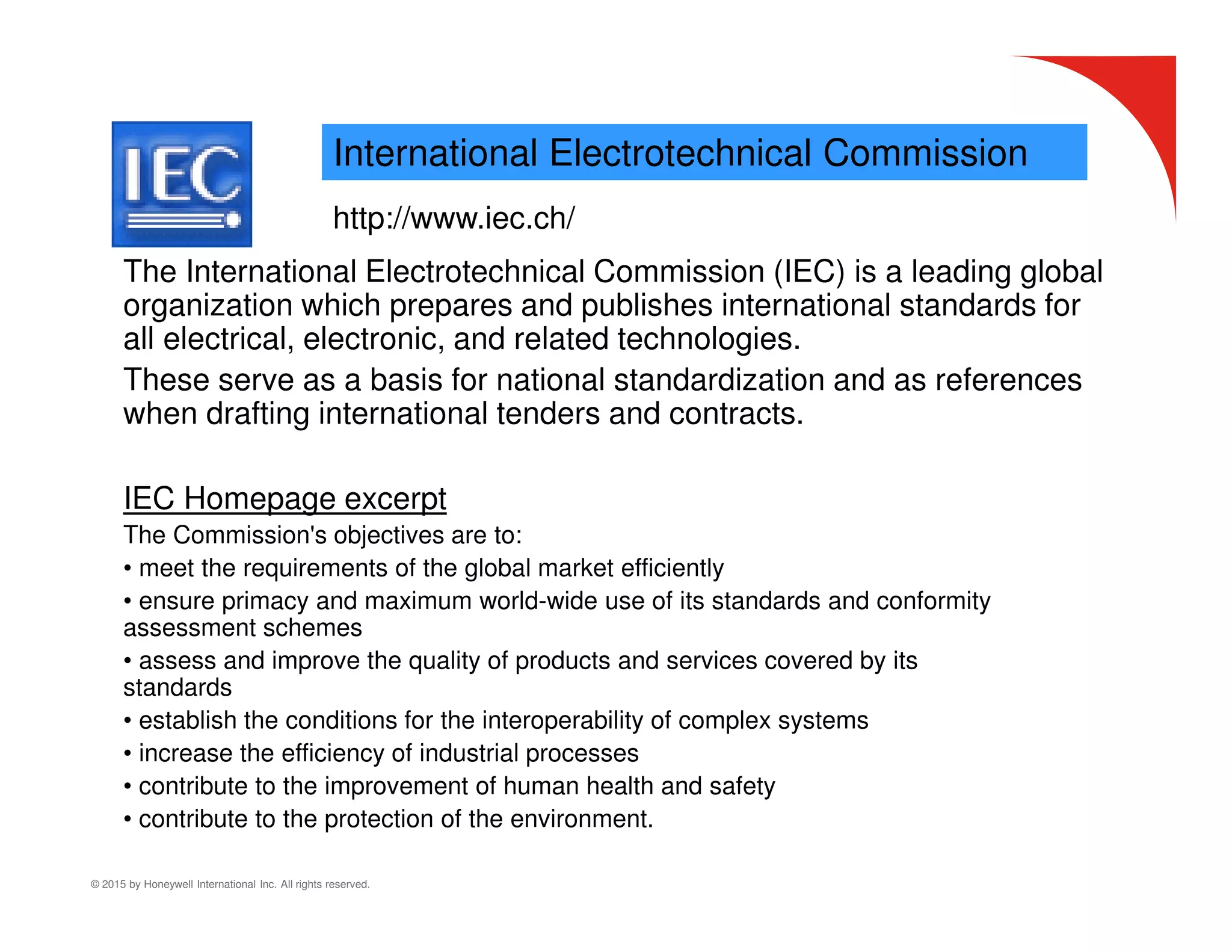


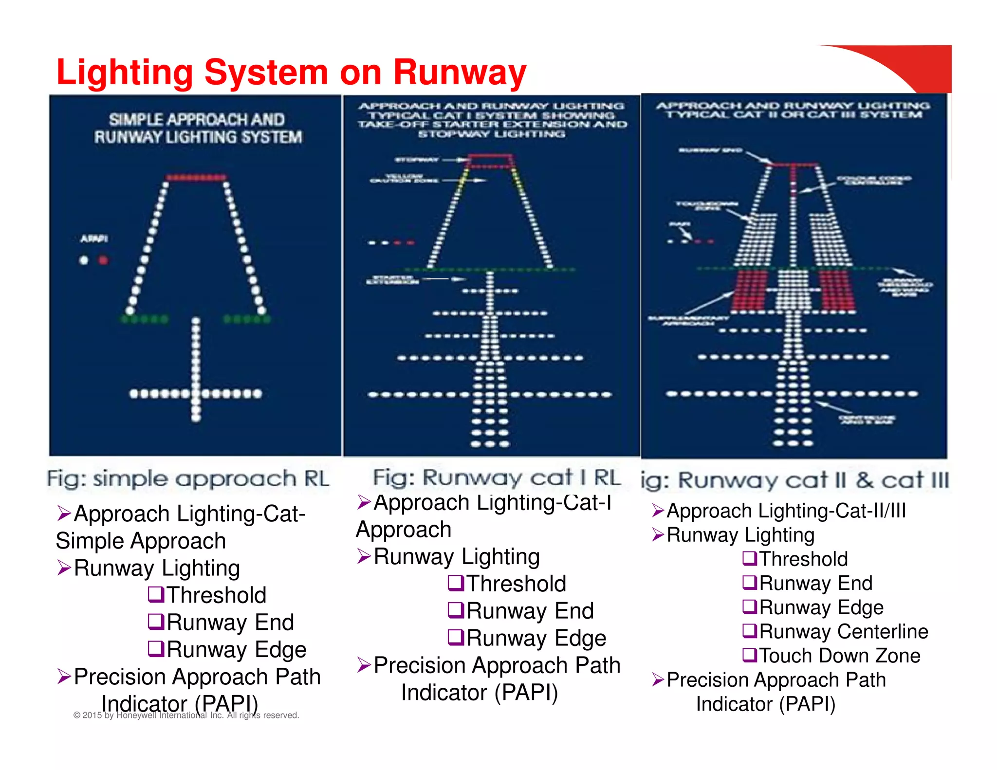


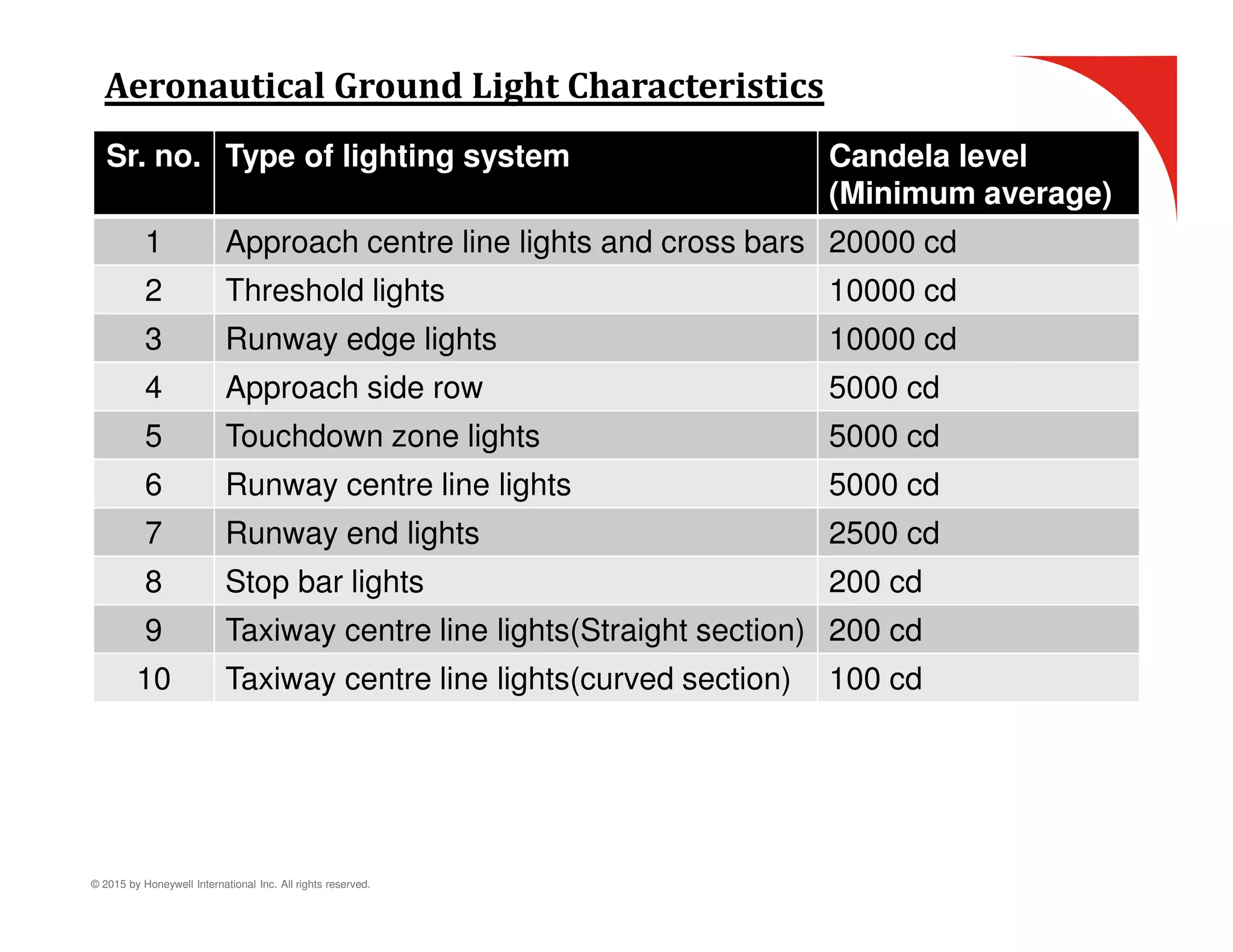


The document discusses airfield ground lighting (AGL) systems. It explains that AGL provides visual aids for aircraft navigation through communication, visual aids like lighting systems, and surveillance. It then defines various aeronautical terms like aerodrome and airfield. It also lists international organizations that set standards for AGL, such as ICAO, FAA, and DGCA, as well as the types of documents they publish to regulate AGL.


