Downloaded 21 times


![Analysis Case Study-2
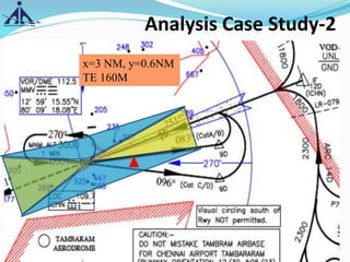
X=3 NM
Y=0.6 NM
AGA=45M+THR ELEV(12 M)=57M
PANS OPS=154M
[{(0.00355X3+0.143X.6)X1852-36.66}+12(THR Ele.)]
REQUESTED TE=160M
6/20/2020 32](https://image.slidesharecdn.com/instrumentapproachproceduresgsr751eprovisionpans-ops-200620085306/85/Instrument-approach-procedures-GSR-751-E-provision-PANS-OPS-ops-32-320.jpg)


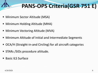
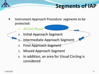
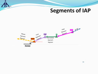
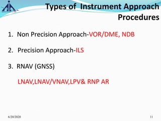
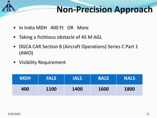
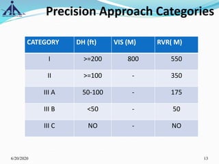
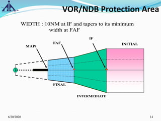
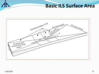
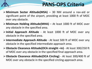
The document outlines the Instrument Approach Procedures (IAP) and their significance in aviation safety, particularly in managing obstacles around airports. It details the criteria set by PANS-OPS for various flight operations and both precision and non-precision approaches, emphasizing critical obstacle clearance requirements and minimum altitudes. Case studies are analyzed to illustrate the impact of these procedures on aircraft operations and safety.


