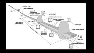
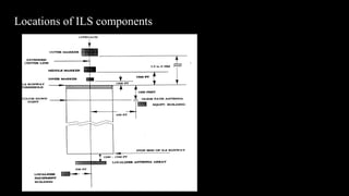
SlideShare a Scribd company logo
Internship At Vadodara Airport
Name: Shubham Sehrawat
Institution: Institute of Technology, Nirma University
Session: 26 April 2016 – 7 July 2016
Index
 Why Airports?
 Facilities at Airports
 Operations of an Airport
 About AAI
 Communication
 Navigation
 ILS(Instrument Landing System)
 Localizer
 Glide path
 Makers
 DVOR
 DME
 Surveillance
 Radar
WHY AIRPORTS?
• An airport is an aerodrome with facilities for flights to take off and land. Airports often
have facilities to store and maintain aircraft, and a control tower. An airport consists of
a landing area, which comprises an aerially accessible open space including at least one
operationally active surface such as a runway for a plane to take off or a helipad, and
often includes adjacent utility buildings such as control towers, hangars and terminals.
Larger airports may have fixed-base operator services, airport aprons, air traffic control
centres, passenger facilities such as restaurants and lounges, and emergency services.
FACILITIES AT AIRPORTS:
1. Most major airports provide commercial outlets for products and services. Most of these
companies, many of which are internationally known brands, are located within the departure
areas. These include clothing boutiques and restaurants. Prices charged for items sold at these
outlets are generally higher than those outside the
2. Cargo Terminal Facilities are areas where international airports export cargo has to be stored
after customs clearance and prior to loading on the aircraft. Similarly import cargo that is
offloaded needs to be in bond before the consignee decides to take delivery. Areas have to be
kept aside for examination of export and import cargo by the airport authorities. Designated
areas or sheds may be given to airlines or freight forward ring agencies.
3. Aircraft and Passenger Boarding Bridges Maintenance, Pilot Operations, Commissioning, Training
Services, aircraft rental, and hangar rental are most often performed by a fixed-base operator
(FBO). At major airports, particularly those used as hubs, airlines may operate their own support
facilities.
OPERATIONS OF AN AIRPORT
• Air traffic control responsibilities at airports are usually divided into at least two main areas: ground and tower,
though a single controller may work both stations. The busiest airports also have clearance delivery, apron control,
and other specialized ATC stations.
• A visual approach slope indicator (VASI) helps pilots fly the approach for landing. Some airports are equipped with a
VHF omnidirectional range (VOR) to help pilots find the direction to the airport. VORs are often accompanied by a
distance measuring equipment (DME) to determine the distance to the VOR. In poor weather, pilots will use an
instrument landing system (ILS) to find the runway and fly the correct approach, even if they cannot see the ground.
The number of instrument approaches based on the use of the Global Positioning System (GPS) is rapidly increasing
and may eventually be the primary means for instrument landings. Larger airports sometimes offer precision
approach radar (PAR), but these systems are more common at military air bases than civilian airports.
• Airport guidance signs provide direction and information to taxiing aircraft and airport vehicles. Smaller aerodromes
may have few or no signs, relying instead on diagrams and charts.
• Many airports have lighting that help guide planes using the runways and taxiways at night or in rain or fog.On
runways, green lights indicate the beginning of the runway for landing, while red lights indicate the end of the runway.
Runway edge lighting consists of white lights spaced out on both sides of the runway, indicating the edge. Along
taxiways, blue lights indicate the taxiway's edge, and some airports have embedded green lights that indicate the
centerline.
• Weather observations at the airport are crucial to safe takeoffs and landings. These weather observations,
predominantly in the METAR format, are available over the radio, through Automatic Terminal Information Service (ATIS),
via the ATC or the Flight Service Station.
• Air safety is an important concern in the operation of an airport, and almost every airfield includes equipment and
procedures for handling emergency situations. Airport crash tender crews are equipped for dealing with airfield
accidents, crew and passenger extractions, and the hazards of highly flammable aviation fuel. The crews are also
trained to deal with situations such as bomb threats, hijacking, and terrorist activities.
ABOUT AAI
• The Airports Authority of India (AAI) (Hindi: भारतीय विमानपत्तन प्राविकरण) under the Ministry of Civil Aviation is
responsible for creating, upgrading, maintaining and managing civil aviation infrastructure in India. It provides Air traffic
management (ATM) services over Indian airspace and adjoining oceanic areas. It also manages a total of 125 Airports,
including 18 International Airports, 7 Customs Airports, 78 Domestic Airports and 26 Civil enclaves at Military Airfields.
AAI covers all major air-routes over Indian landmass via 29 Radar installations at 11 locations along with 700VOR/DVOR
installations co-located with Distance Measuring Equipment (DME). 52 runways are provided with Instrument landing
system (ILS) installations with Night Landing Facilities at most of these airports and Automatic Message Switching System
at 15 Airports.
• Implementation of GPS And Geo Augmented Navigation (GAGAN) jointly with ISRO which when put to operation would be
one of the four such systems in the world.
• Most of AAI's revenue is generated from landing/parking fees and fees collected by providing CNS & ATC services to
aircraft over the Indian airspace.
COMMUNICATION
• Communication is the exchange of voice and data information between the pilot and air traffic controllers or
flight information centres.
• VHF (Very High Frequency)(Frequency range : 30 – 300 Mhz.) propogation characteristics are ideal for short-
distance terrestrial communication. VHF is also less affected by atmospheric and interference from electrical
equipment.
• The VHF airband uses the frequencies between 108 and 137 MHz. The lowest 10 MHz of the band, from 108–
117.95 MHz, is split into 200 narrow-band channels of 50 kHz. These are reserved for navigational aids such
as VOR beacons, and precision approach systems such as ILS localizers.
• At Vadodara airport the VHF RT frequency is 123.250 Mhz.
• Emergency frequency is 121.500 MHZ.
NAVIGATION(IMPORTANT PARTS)
• Instrument Landing System(ILS)
• The Instrument Landing System (ILS) is an instrument presented, pilot interpreted, precision approach aid. The system
provides the pilot with instrument indications for predetermined final approach path.
• The Instrument Landing System (ILS) is an internationally normalized system for navigation of aircrafts upon the final
approach for landing. It was accepted as a standard system by the ICAO, (International Civil Aviation Organization) in 1947.
• DVOR (Doppler VHF Omni Range)
• DVOR ground station sends out an omnidirectional master signal, and a highly directional second signal is propagated by a
phased antenna array and rotates clockwise in space 30 times a second. This signal is timed so that its phase (compared to
the master) varies as the secondary signal rotates, and this phase difference is the same as the angular direction of the
'spinning' signal, (so that when the signal is being sent 90 degrees clockwise from north, the signal is 90 degrees out of
phase with the master)
• The predictable accuracy of the VOR system is ±1.4°. However, test data indicate that 99.94% of the time a VOR system has
less than ±0.35° of error. Internal monitoring of a VOR station will shut it down, or change-over to a Standby system if the
station error exceeds some limit. A Doppler VOR beacon will typically change-over or shutdown when the bearing error
exceeds 1.0
INSTRUMENT LANDING SYSTEM(ILS)
• There are three main elements in the complete ILS:
• A localizer radio beam to furnish directional guidance to and along the runway
• A glide path radio beam to furnish vertical guidance at the correct descent angle to the runway touchdown point
• Fan markers (outer marker and middle marker).
• In some cases DME has been authorized for use when markers are not available or cannot be installed.
• A suitable radio navigation aid is provided on most installations to assist in interception of the localizer and holding procedures. At
some locations two of these aids are provided. This aid can be either a VOR or a low-powered NDB (Locator).
ILS Parameter ILS Component
a. Azimuth Approach Guidance Provided by Localizer
b. Elevation Approach Guidance Provided by Glide Path
c. Fixed Distances from Threshold Provided by Marker Beacons
d. Range from touch down point Provided by DME
LOCALIZER
• The localizer aerial is on the runway extended centerline at the opposite end to the approach end,
at a distance which ensures that it lies below the runway take-off obstruction clearance plane. The
transmitter building is usually located 100–120 meters to the side of the aerial. The field pattern
radiated by the localizer is with the course line lying along the extended runway centerline. The
localizer beam ‘width’, as it is interpreted by the travel of the localizer needle on the aircraft cross
pointer indicator from full deflection in the blue sector (150-hertz) to full deflection in the yellow
sector (90- hertz) is normally 5° for uncategorized systems and all other systems are adjusted to
210 meters wide at the landing threshold. Total width in terms of degrees will depend on position
of aerials and length of runway. The equipment is designed to provide a usable on-course signal at
a minimum distance of 25 nautical miles from the runway at a minimum altitude of 2,000 feet
above the threshold.
• Picture on next slide is representation of ILS.
• The localizer frequency at Vadodara airport:110.5 Mhz. The ident Code: IVDD.
Locations of ILS components
GLIDE PATH
• The glide slope, or angle of the descent plane provides the vertical guidance for the pilot during an approach. It’s created by a ground UHF
transmitter containing an antenna system operating in the range of 329.30-335.00 MHz, with a channel separation of 50 kHz. The
transmitter is located 750-1250 ft. from the beginning of the runway and 400-600 ft. from it’s axis. The observed tolerance is ±0.5°. The
UHF glide slope is paired with the corresponding frequency of the VHF localizer.
• Like the signal of the localizer, so does the signal of the glide slope consist of two intersected radiation patterns, modulated at 90 and 150
Hz. However unlike the localizer, these signals are arranged on top of each other and emitted along the path of approach. The thickness of
the overlapping field is 0.7° over as well as under the optimal glide slope.
• Vadodara airport frequency : 329.6 Mhz.
MARKERS
• The marker beacons used with the ILS are low powered, operate on a frequency of 75 MHz and radiate a fan shaped field
pattern. There are usually two marker beacons:
• Outer Marker The outer marker is located approximately 3.9 nautical miles from the runway threshold and is aligned across
the front beam of the localizer. Its purpose is to provide height, distance and equipment functioning checks to aircraft on final
approach. It is modulated at 400-hertz and keyed to transmit dashes continuously at a rate of two per second.
• Middle Marker The middle marker, also a fan marker, is aligned across the front beam of the localizer and is situated
approximately 1050 meters from the runway threshold. Its purpose is to indicate the imminence, in low visibility conditions,
of visual approach guidance. This marker is modulated at 1300-hertz and keyed to transmit alternate dots and dashes. Some
overseas installations utilize a third marker beacon (inner marker) which is modulated at 3000-hertz, identified by a keyed
continuous signal of six dots per second and is located 75–450 meters from the runway threshold. There are no inner
markers associated with ILS installations in Australia.
DOPPLER VHF OMNI RANGE(DVOR)
 Using the VOR receiver installed in the aircraft the pilot is able to obtain the following information .
• The azimuth indication of the aircraft’s position relative to the ground beacon, i.e. the angle
between magnetic North and the direction ground beacon to aircraft.
• The bearing which indicates whether the aircraft is flying to the left or right of the preselected
course (position line) or whether it is exactly on it.
• The "from/to" indication which shows whether the aircraft is flying toward the DVOR beacon or
away from it
• Vadodara airport DVOR frequency: 117.300 Mhz. Ident Code: QQZ.
PRINCIPLE OF DVOR
• Reference Signal : the 30 Hz modulation which amplitude−modulates (AM) the VHF carrier now acts as
the reference signal. The modulated carrier signal is transmitted Omni directionally by a center
antenna. It is amplitude−modulated with the voice (300...3000 Hz) and the identity Morse code in
addition to the 30 Hz reference signal.
• Variable Signal: the 30 Hz modulation which frequency−modulated (FM) 30 Hz modulation (variable
signal) is contained in the 9960 Hz subcarrier. The 9960 Hz subcarrier signal is transmitted directionally
by a sideband radiator antenna, which can be considered to be rotating along a circular path. The
radiated sideband frequency is offset by +9960 Hz or −9960 Hz with respect to the carrier frequency.
• ICAO stipulated ±480 Hz signal in order to obtain the frequency deviation.
FREQUENCY SPECTRUM OF THE DVOR RADIO BEACON
DVOR EQUIPMENT
DISTANCE MEASURING EQUIPMENT(DME)
• Distance measuring equipment (DME) is a transponder-based radio navigation technology that measures slant range distance by timing the
propagation delay of VHF or UHF radio signals.
• Frequency Bands : UHF (300 MHz to 3GHz)
• 960 MHz to 1215 MHz(For DME)
• Aircraft use DME to determine their distance from a land-based transponder by sending and receiving pulse pairs – two pulses of fixed
duration and separation. The ground stations are typically co-located with VORs. A typical DME ground transponder system for en-route or
terminal navigation will have a 1 kW peak pulse output on the assigned UHF channel.
• A low-power DME can be co-located with an ILS Localizer antenna installation where it provides an accurate distance to touchdown function,
similar to that otherwise provided by ILS Marker Beacons.
• The DME system is composed of a UHF transmitter/receiver (interrogator) in the aircraft and a UHF receiver/transmitter (transponder) on
the ground.
• Vadodara airport has two DME’s.
• One High power DME(1 KW) paired with the DVOR. Frequency : TX -1144 RX-1207 . ID : QQZ.
• One Low power DME(100 W) paired with the ILS. It is placed at GP. Frequency : TX -1003 RX-1066.
SURVELIANCE
• AMSS is a computer based system, centered on the Aeronautical Fixed Telecommunication Network
(AFTN) for exchange of Aeronautical messages by means of auto-switching for distribution of
messages to its destination(s). This system works on store and forward principle.
• AMSS is an acronym for Automatic Message Switching System. It has four major areas:
• (1) System (2) Switching (3) Messages (4) Automation
• System: AMSS is a dual architecture computer based system which consists of few servers and
workstations which are linked to each other over a local area network as well as other
equipment/devices for data communication.
• Messages: AMSS is mainly for exchange of AFTN messages, but at the same time AMSS can handle
some non-AFTN messages like AMS messages (formally known as HFRT/Radio messages).
• Switching: AMSS receives the messages from the terminals connected via other switches, and after
analysing, stores the messages as well as automatically retransmits the messages to their destination.
During the above process it uses switching system, which allows on demand basis the connection of any
combination of source and sink stations. AFTN switching system can be classified into three major
categories:
• 1)Line Switching 2)Message Switching 3)Packet Switching
• AMSS consists of three major components: 1) Core System 2) Recording System 3) User’s terminal
• Core System: It incorporates communication adapters, protocols/suites, routing and gateway facilities. The
core system is composed of two identical computer machines (known as AMSS main servers) which run in an
operational/hot standby combination. Both units supervise each other‘s software and hardware
• Recording System: It has two identical mass data storage devices for storing of all incoming and outgoing
AFTN messages. It also has two identical mirrored Database servers which are operated in parallel. The
mirroring between the two database servers is performed in the background to store specified type
messages like NOTAM, MET, ATC, HFRT, with no effect on the regular operation.
• User’s Terminals: It is the interface between user and the system with capability for uniform administration
and monitoring facilities for all system components, networks and data as well as exchange of data as per
requirement of users vide different type application software. Any number of user terminals (maximum 60)
can be installed and used simultaneously.
RADAR
• RADAR is an acronym coined by the US Navy from the words RAdio Detection And Ranging.
Radar is basically a means for gathering information about distant objects called “targets” by sending
electromagnetic waves at them and analysing the returns called the “echoes”.
• CLASSIFICATION OF RADARS
• Primary Radar: Cooperation of targets are not required for detection.
• Secondary Radar: Active cooperation of targets are required for finding range and other details of the targets.
• CW Radar: Can detect moving targets and it’s velocity.
• CW FM Radar: Can detect range using FM Signals. Pulsed Radar: Uses pulse modulated micro wave signals for
detecting range and velocity of targets.
• AAI RADAR’s are available at Guwahati, Ahmedabad, Berhampur, Nagpur, Varanasi, Mangalore, Hyderabad ,
Bangalore, Kolkata, Chennai, Bellary, Vizag, Katihar, Jharsuguda, Bhopal, Porbandar , Udaipur, Mumbai,
Trivandrum, and Delhi.
318099023-Internship-at-AAI-Baroda.pdf

More Related Content

Similar to 318099023-Internship-at-AAI-Baroda.pdf

PIA internship report
PIA internship reportPIA internship report
PIA internship report
Muhammad Dildar
 
cnsreportpresentation-200726152923.pdf
cnsreportpresentation-200726152923.pdfcnsreportpresentation-200726152923.pdf
cnsreportpresentation-200726152923.pdf
ChitranshKadare
 
CNS AAI Internship Presentation
CNS AAI Internship PresentationCNS AAI Internship Presentation
CNS AAI Internship Presentation
PRAJJWAL ROHELA
 
Presentation on AAI, Jaipur
Presentation on AAI, JaipurPresentation on AAI, Jaipur
Presentation on AAI, Jaipur
Khushboo Goyal
 
Airports authority of india (aai) training report
Airports authority of india (aai) training reportAirports authority of india (aai) training report
Airports authority of india (aai) training report
Arnab Bhattacharya
 
Airport Authority of India
Airport Authority of IndiaAirport Authority of India
Airport Authority of India
Uma Mahesh
 
AAI Regional Training Center bhopal ,.pptx
AAI Regional Training  Center bhopal ,.pptxAAI Regional Training  Center bhopal ,.pptx
AAI Regional Training Center bhopal ,.pptx
ChitranshKadare
 
Instrument landing system
Instrument landing systemInstrument landing system
Instrument landing system
Vishwa Fonseka
 
Training report on airport authority of india(a
Training report on airport authority of india(aTraining report on airport authority of india(a
Training report on airport authority of india(aUtkarshSingh UT
 
Quick reference guide ans
Quick reference guide  ansQuick reference guide  ans
Quick reference guide ans
Zameer Basha
 
(CNS)Submited-Dr Donohue.ppt
(CNS)Submited-Dr Donohue.ppt(CNS)Submited-Dr Donohue.ppt
(CNS)Submited-Dr Donohue.ppt
AhwanPradhan1
 
Air Traffic Control.pptx
Air Traffic Control.pptxAir Traffic Control.pptx
Air Traffic Control.pptx
bharathikv29
 
Industrial Training at Airports Authority of India
Industrial Training at Airports Authority of IndiaIndustrial Training at Airports Authority of India
Industrial Training at Airports Authority of India
Nikhil Gupta
 
Avionics-Embedded systems-basic
Avionics-Embedded systems-basicAvionics-Embedded systems-basic
Avionics-Embedded systems-basic
Sejj Lingayat
 
Airports Authority of India Industrial Training Presentation
Airports Authority of India Industrial Training PresentationAirports Authority of India Industrial Training Presentation
Airports Authority of India Industrial Training Presentation
Anubhav Mahajan
 
Nav_Aids_Presentation_NA.pptx
Nav_Aids_Presentation_NA.pptxNav_Aids_Presentation_NA.pptx
Nav_Aids_Presentation_NA.pptx
mancangkul1
 
RADIO NAVIGATION.pptx
RADIO NAVIGATION.pptxRADIO NAVIGATION.pptx
RADIO NAVIGATION.pptx
ssuser99ea8e
 

Similar to 318099023-Internship-at-AAI-Baroda.pdf (20)

PIA internship report
PIA internship reportPIA internship report
PIA internship report
 
cnsreportpresentation-200726152923.pdf
cnsreportpresentation-200726152923.pdfcnsreportpresentation-200726152923.pdf
cnsreportpresentation-200726152923.pdf
 
CNS AAI Internship Presentation
CNS AAI Internship PresentationCNS AAI Internship Presentation
CNS AAI Internship Presentation
 
Presentation on AAI, Jaipur
Presentation on AAI, JaipurPresentation on AAI, Jaipur
Presentation on AAI, Jaipur
 
Airports authority of india (aai) training report
Airports authority of india (aai) training reportAirports authority of india (aai) training report
Airports authority of india (aai) training report
 
Airport Authority of India
Airport Authority of IndiaAirport Authority of India
Airport Authority of India
 
Navigation aids
Navigation aidsNavigation aids
Navigation aids
 
AAI Regional Training Center bhopal ,.pptx
AAI Regional Training  Center bhopal ,.pptxAAI Regional Training  Center bhopal ,.pptx
AAI Regional Training Center bhopal ,.pptx
 
FINAL
FINALFINAL
FINAL
 
report
reportreport
report
 
Instrument landing system
Instrument landing systemInstrument landing system
Instrument landing system
 
Training report on airport authority of india(a
Training report on airport authority of india(aTraining report on airport authority of india(a
Training report on airport authority of india(a
 
Quick reference guide ans
Quick reference guide  ansQuick reference guide  ans
Quick reference guide ans
 
(CNS)Submited-Dr Donohue.ppt
(CNS)Submited-Dr Donohue.ppt(CNS)Submited-Dr Donohue.ppt
(CNS)Submited-Dr Donohue.ppt
 
Air Traffic Control.pptx
Air Traffic Control.pptxAir Traffic Control.pptx
Air Traffic Control.pptx
 
Industrial Training at Airports Authority of India
Industrial Training at Airports Authority of IndiaIndustrial Training at Airports Authority of India
Industrial Training at Airports Authority of India
 
Avionics-Embedded systems-basic
Avionics-Embedded systems-basicAvionics-Embedded systems-basic
Avionics-Embedded systems-basic
 
Airports Authority of India Industrial Training Presentation
Airports Authority of India Industrial Training PresentationAirports Authority of India Industrial Training Presentation
Airports Authority of India Industrial Training Presentation
 
Nav_Aids_Presentation_NA.pptx
Nav_Aids_Presentation_NA.pptxNav_Aids_Presentation_NA.pptx
Nav_Aids_Presentation_NA.pptx
 
RADIO NAVIGATION.pptx
RADIO NAVIGATION.pptxRADIO NAVIGATION.pptx
RADIO NAVIGATION.pptx
 

Recently uploaded

power quality voltage fluctuation UNIT - I.pptx
power quality voltage fluctuation UNIT - I.pptxpower quality voltage fluctuation UNIT - I.pptx
power quality voltage fluctuation UNIT - I.pptx
ViniHema
 
在线办理(ANU毕业证书)澳洲国立大学毕业证录取通知书一模一样
在线办理(ANU毕业证书)澳洲国立大学毕业证录取通知书一模一样在线办理(ANU毕业证书)澳洲国立大学毕业证录取通知书一模一样
在线办理(ANU毕业证书)澳洲国立大学毕业证录取通知书一模一样
obonagu
 
The Benefits and Techniques of Trenchless Pipe Repair.pdf
The Benefits and Techniques of Trenchless Pipe Repair.pdfThe Benefits and Techniques of Trenchless Pipe Repair.pdf
The Benefits and Techniques of Trenchless Pipe Repair.pdf
Pipe Restoration Solutions
 
Democratizing Fuzzing at Scale by Abhishek Arya
Democratizing Fuzzing at Scale by Abhishek AryaDemocratizing Fuzzing at Scale by Abhishek Arya
Democratizing Fuzzing at Scale by Abhishek Arya
abh.arya
 
addressing modes in computer architecture
addressing modes  in computer architectureaddressing modes  in computer architecture
addressing modes in computer architecture
ShahidSultan24
 
Industrial Training at Shahjalal Fertilizer Company Limited (SFCL)
Industrial Training at Shahjalal Fertilizer Company Limited (SFCL)Industrial Training at Shahjalal Fertilizer Company Limited (SFCL)
Industrial Training at Shahjalal Fertilizer Company Limited (SFCL)
MdTanvirMahtab2
 
Architectural Portfolio Sean Lockwood
Architectural Portfolio Sean LockwoodArchitectural Portfolio Sean Lockwood
Architectural Portfolio Sean Lockwood
seandesed
 
WATER CRISIS and its solutions-pptx 1234
WATER CRISIS and its solutions-pptx 1234WATER CRISIS and its solutions-pptx 1234
WATER CRISIS and its solutions-pptx 1234
AafreenAbuthahir2
 
Quality defects in TMT Bars, Possible causes and Potential Solutions.
Quality defects in TMT Bars, Possible causes and Potential Solutions.Quality defects in TMT Bars, Possible causes and Potential Solutions.
Quality defects in TMT Bars, Possible causes and Potential Solutions.
PrashantGoswami42
 
Courier management system project report.pdf
Courier management system project report.pdfCourier management system project report.pdf
Courier management system project report.pdf
Kamal Acharya
 
ASME IX(9) 2007 Full Version .pdf
ASME IX(9)  2007 Full Version       .pdfASME IX(9)  2007 Full Version       .pdf
ASME IX(9) 2007 Full Version .pdf
AhmedHussein950959
 
HYDROPOWER - Hydroelectric power generation
HYDROPOWER - Hydroelectric power generationHYDROPOWER - Hydroelectric power generation
HYDROPOWER - Hydroelectric power generation
Robbie Edward Sayers
 
DESIGN A COTTON SEED SEPARATION MACHINE.docx
DESIGN A COTTON SEED SEPARATION MACHINE.docxDESIGN A COTTON SEED SEPARATION MACHINE.docx
DESIGN A COTTON SEED SEPARATION MACHINE.docx
FluxPrime1
 
Forklift Classes Overview by Intella Parts
Forklift Classes Overview by Intella PartsForklift Classes Overview by Intella Parts
Forklift Classes Overview by Intella Parts
Intella Parts
 
Standard Reomte Control Interface - Neometrix
Standard Reomte Control Interface - NeometrixStandard Reomte Control Interface - Neometrix
Standard Reomte Control Interface - Neometrix
Neometrix_Engineering_Pvt_Ltd
 
Hybrid optimization of pumped hydro system and solar- Engr. Abdul-Azeez.pdf
Hybrid optimization of pumped hydro system and solar- Engr. Abdul-Azeez.pdfHybrid optimization of pumped hydro system and solar- Engr. Abdul-Azeez.pdf
Hybrid optimization of pumped hydro system and solar- Engr. Abdul-Azeez.pdf
fxintegritypublishin
 
ethical hacking-mobile hacking methods.ppt
ethical hacking-mobile hacking methods.pptethical hacking-mobile hacking methods.ppt
ethical hacking-mobile hacking methods.ppt
Jayaprasanna4
 
Pile Foundation by Venkatesh Taduvai (Sub Geotechnical Engineering II)-conver...
Pile Foundation by Venkatesh Taduvai (Sub Geotechnical Engineering II)-conver...Pile Foundation by Venkatesh Taduvai (Sub Geotechnical Engineering II)-conver...
Pile Foundation by Venkatesh Taduvai (Sub Geotechnical Engineering II)-conver...
AJAYKUMARPUND1
 
The role of big data in decision making.
The role of big data in decision making.The role of big data in decision making.
The role of big data in decision making.
ankuprajapati0525
 
LIGA(E)11111111111111111111111111111111111111111.ppt
LIGA(E)11111111111111111111111111111111111111111.pptLIGA(E)11111111111111111111111111111111111111111.ppt
LIGA(E)11111111111111111111111111111111111111111.ppt
ssuser9bd3ba
 

Recently uploaded (20)

power quality voltage fluctuation UNIT - I.pptx
power quality voltage fluctuation UNIT - I.pptxpower quality voltage fluctuation UNIT - I.pptx
power quality voltage fluctuation UNIT - I.pptx
 
在线办理(ANU毕业证书)澳洲国立大学毕业证录取通知书一模一样
在线办理(ANU毕业证书)澳洲国立大学毕业证录取通知书一模一样在线办理(ANU毕业证书)澳洲国立大学毕业证录取通知书一模一样
在线办理(ANU毕业证书)澳洲国立大学毕业证录取通知书一模一样
 
The Benefits and Techniques of Trenchless Pipe Repair.pdf
The Benefits and Techniques of Trenchless Pipe Repair.pdfThe Benefits and Techniques of Trenchless Pipe Repair.pdf
The Benefits and Techniques of Trenchless Pipe Repair.pdf
 
Democratizing Fuzzing at Scale by Abhishek Arya
Democratizing Fuzzing at Scale by Abhishek AryaDemocratizing Fuzzing at Scale by Abhishek Arya
Democratizing Fuzzing at Scale by Abhishek Arya
 
addressing modes in computer architecture
addressing modes  in computer architectureaddressing modes  in computer architecture
addressing modes in computer architecture
 
Industrial Training at Shahjalal Fertilizer Company Limited (SFCL)
Industrial Training at Shahjalal Fertilizer Company Limited (SFCL)Industrial Training at Shahjalal Fertilizer Company Limited (SFCL)
Industrial Training at Shahjalal Fertilizer Company Limited (SFCL)
 
Architectural Portfolio Sean Lockwood
Architectural Portfolio Sean LockwoodArchitectural Portfolio Sean Lockwood
Architectural Portfolio Sean Lockwood
 
WATER CRISIS and its solutions-pptx 1234
WATER CRISIS and its solutions-pptx 1234WATER CRISIS and its solutions-pptx 1234
WATER CRISIS and its solutions-pptx 1234
 
Quality defects in TMT Bars, Possible causes and Potential Solutions.
Quality defects in TMT Bars, Possible causes and Potential Solutions.Quality defects in TMT Bars, Possible causes and Potential Solutions.
Quality defects in TMT Bars, Possible causes and Potential Solutions.
 
Courier management system project report.pdf
Courier management system project report.pdfCourier management system project report.pdf
Courier management system project report.pdf
 
ASME IX(9) 2007 Full Version .pdf
ASME IX(9)  2007 Full Version       .pdfASME IX(9)  2007 Full Version       .pdf
ASME IX(9) 2007 Full Version .pdf
 
HYDROPOWER - Hydroelectric power generation
HYDROPOWER - Hydroelectric power generationHYDROPOWER - Hydroelectric power generation
HYDROPOWER - Hydroelectric power generation
 
DESIGN A COTTON SEED SEPARATION MACHINE.docx
DESIGN A COTTON SEED SEPARATION MACHINE.docxDESIGN A COTTON SEED SEPARATION MACHINE.docx
DESIGN A COTTON SEED SEPARATION MACHINE.docx
 
Forklift Classes Overview by Intella Parts
Forklift Classes Overview by Intella PartsForklift Classes Overview by Intella Parts
Forklift Classes Overview by Intella Parts
 
Standard Reomte Control Interface - Neometrix
Standard Reomte Control Interface - NeometrixStandard Reomte Control Interface - Neometrix
Standard Reomte Control Interface - Neometrix
 
Hybrid optimization of pumped hydro system and solar- Engr. Abdul-Azeez.pdf
Hybrid optimization of pumped hydro system and solar- Engr. Abdul-Azeez.pdfHybrid optimization of pumped hydro system and solar- Engr. Abdul-Azeez.pdf
Hybrid optimization of pumped hydro system and solar- Engr. Abdul-Azeez.pdf
 
ethical hacking-mobile hacking methods.ppt
ethical hacking-mobile hacking methods.pptethical hacking-mobile hacking methods.ppt
ethical hacking-mobile hacking methods.ppt
 
Pile Foundation by Venkatesh Taduvai (Sub Geotechnical Engineering II)-conver...
Pile Foundation by Venkatesh Taduvai (Sub Geotechnical Engineering II)-conver...Pile Foundation by Venkatesh Taduvai (Sub Geotechnical Engineering II)-conver...
Pile Foundation by Venkatesh Taduvai (Sub Geotechnical Engineering II)-conver...
 
The role of big data in decision making.
The role of big data in decision making.The role of big data in decision making.
The role of big data in decision making.
 
LIGA(E)11111111111111111111111111111111111111111.ppt
LIGA(E)11111111111111111111111111111111111111111.pptLIGA(E)11111111111111111111111111111111111111111.ppt
LIGA(E)11111111111111111111111111111111111111111.ppt
 

318099023-Internship-at-AAI-Baroda.pdf

  • 1. Internship At Vadodara Airport Name: Shubham Sehrawat Institution: Institute of Technology, Nirma University Session: 26 April 2016 – 7 July 2016
  • 2. Index  Why Airports?  Facilities at Airports  Operations of an Airport  About AAI  Communication  Navigation  ILS(Instrument Landing System)  Localizer  Glide path  Makers  DVOR  DME  Surveillance  Radar
  • 3. WHY AIRPORTS? • An airport is an aerodrome with facilities for flights to take off and land. Airports often have facilities to store and maintain aircraft, and a control tower. An airport consists of a landing area, which comprises an aerially accessible open space including at least one operationally active surface such as a runway for a plane to take off or a helipad, and often includes adjacent utility buildings such as control towers, hangars and terminals. Larger airports may have fixed-base operator services, airport aprons, air traffic control centres, passenger facilities such as restaurants and lounges, and emergency services.
  • 4. FACILITIES AT AIRPORTS: 1. Most major airports provide commercial outlets for products and services. Most of these companies, many of which are internationally known brands, are located within the departure areas. These include clothing boutiques and restaurants. Prices charged for items sold at these outlets are generally higher than those outside the 2. Cargo Terminal Facilities are areas where international airports export cargo has to be stored after customs clearance and prior to loading on the aircraft. Similarly import cargo that is offloaded needs to be in bond before the consignee decides to take delivery. Areas have to be kept aside for examination of export and import cargo by the airport authorities. Designated areas or sheds may be given to airlines or freight forward ring agencies. 3. Aircraft and Passenger Boarding Bridges Maintenance, Pilot Operations, Commissioning, Training Services, aircraft rental, and hangar rental are most often performed by a fixed-base operator (FBO). At major airports, particularly those used as hubs, airlines may operate their own support facilities.
  • 5. OPERATIONS OF AN AIRPORT • Air traffic control responsibilities at airports are usually divided into at least two main areas: ground and tower, though a single controller may work both stations. The busiest airports also have clearance delivery, apron control, and other specialized ATC stations. • A visual approach slope indicator (VASI) helps pilots fly the approach for landing. Some airports are equipped with a VHF omnidirectional range (VOR) to help pilots find the direction to the airport. VORs are often accompanied by a distance measuring equipment (DME) to determine the distance to the VOR. In poor weather, pilots will use an instrument landing system (ILS) to find the runway and fly the correct approach, even if they cannot see the ground. The number of instrument approaches based on the use of the Global Positioning System (GPS) is rapidly increasing and may eventually be the primary means for instrument landings. Larger airports sometimes offer precision approach radar (PAR), but these systems are more common at military air bases than civilian airports.
  • 6. • Airport guidance signs provide direction and information to taxiing aircraft and airport vehicles. Smaller aerodromes may have few or no signs, relying instead on diagrams and charts. • Many airports have lighting that help guide planes using the runways and taxiways at night or in rain or fog.On runways, green lights indicate the beginning of the runway for landing, while red lights indicate the end of the runway. Runway edge lighting consists of white lights spaced out on both sides of the runway, indicating the edge. Along taxiways, blue lights indicate the taxiway's edge, and some airports have embedded green lights that indicate the centerline. • Weather observations at the airport are crucial to safe takeoffs and landings. These weather observations, predominantly in the METAR format, are available over the radio, through Automatic Terminal Information Service (ATIS), via the ATC or the Flight Service Station. • Air safety is an important concern in the operation of an airport, and almost every airfield includes equipment and procedures for handling emergency situations. Airport crash tender crews are equipped for dealing with airfield accidents, crew and passenger extractions, and the hazards of highly flammable aviation fuel. The crews are also trained to deal with situations such as bomb threats, hijacking, and terrorist activities.
  • 7. ABOUT AAI • The Airports Authority of India (AAI) (Hindi: भारतीय विमानपत्तन प्राविकरण) under the Ministry of Civil Aviation is responsible for creating, upgrading, maintaining and managing civil aviation infrastructure in India. It provides Air traffic management (ATM) services over Indian airspace and adjoining oceanic areas. It also manages a total of 125 Airports, including 18 International Airports, 7 Customs Airports, 78 Domestic Airports and 26 Civil enclaves at Military Airfields. AAI covers all major air-routes over Indian landmass via 29 Radar installations at 11 locations along with 700VOR/DVOR installations co-located with Distance Measuring Equipment (DME). 52 runways are provided with Instrument landing system (ILS) installations with Night Landing Facilities at most of these airports and Automatic Message Switching System at 15 Airports. • Implementation of GPS And Geo Augmented Navigation (GAGAN) jointly with ISRO which when put to operation would be one of the four such systems in the world. • Most of AAI's revenue is generated from landing/parking fees and fees collected by providing CNS & ATC services to aircraft over the Indian airspace.
  • 8. COMMUNICATION • Communication is the exchange of voice and data information between the pilot and air traffic controllers or flight information centres. • VHF (Very High Frequency)(Frequency range : 30 – 300 Mhz.) propogation characteristics are ideal for short- distance terrestrial communication. VHF is also less affected by atmospheric and interference from electrical equipment. • The VHF airband uses the frequencies between 108 and 137 MHz. The lowest 10 MHz of the band, from 108– 117.95 MHz, is split into 200 narrow-band channels of 50 kHz. These are reserved for navigational aids such as VOR beacons, and precision approach systems such as ILS localizers. • At Vadodara airport the VHF RT frequency is 123.250 Mhz. • Emergency frequency is 121.500 MHZ.
  • 9. NAVIGATION(IMPORTANT PARTS) • Instrument Landing System(ILS) • The Instrument Landing System (ILS) is an instrument presented, pilot interpreted, precision approach aid. The system provides the pilot with instrument indications for predetermined final approach path. • The Instrument Landing System (ILS) is an internationally normalized system for navigation of aircrafts upon the final approach for landing. It was accepted as a standard system by the ICAO, (International Civil Aviation Organization) in 1947. • DVOR (Doppler VHF Omni Range) • DVOR ground station sends out an omnidirectional master signal, and a highly directional second signal is propagated by a phased antenna array and rotates clockwise in space 30 times a second. This signal is timed so that its phase (compared to the master) varies as the secondary signal rotates, and this phase difference is the same as the angular direction of the 'spinning' signal, (so that when the signal is being sent 90 degrees clockwise from north, the signal is 90 degrees out of phase with the master) • The predictable accuracy of the VOR system is ±1.4°. However, test data indicate that 99.94% of the time a VOR system has less than ±0.35° of error. Internal monitoring of a VOR station will shut it down, or change-over to a Standby system if the station error exceeds some limit. A Doppler VOR beacon will typically change-over or shutdown when the bearing error exceeds 1.0
  • 10. INSTRUMENT LANDING SYSTEM(ILS) • There are three main elements in the complete ILS: • A localizer radio beam to furnish directional guidance to and along the runway • A glide path radio beam to furnish vertical guidance at the correct descent angle to the runway touchdown point • Fan markers (outer marker and middle marker). • In some cases DME has been authorized for use when markers are not available or cannot be installed. • A suitable radio navigation aid is provided on most installations to assist in interception of the localizer and holding procedures. At some locations two of these aids are provided. This aid can be either a VOR or a low-powered NDB (Locator). ILS Parameter ILS Component a. Azimuth Approach Guidance Provided by Localizer b. Elevation Approach Guidance Provided by Glide Path c. Fixed Distances from Threshold Provided by Marker Beacons d. Range from touch down point Provided by DME
  • 11. LOCALIZER • The localizer aerial is on the runway extended centerline at the opposite end to the approach end, at a distance which ensures that it lies below the runway take-off obstruction clearance plane. The transmitter building is usually located 100–120 meters to the side of the aerial. The field pattern radiated by the localizer is with the course line lying along the extended runway centerline. The localizer beam ‘width’, as it is interpreted by the travel of the localizer needle on the aircraft cross pointer indicator from full deflection in the blue sector (150-hertz) to full deflection in the yellow sector (90- hertz) is normally 5° for uncategorized systems and all other systems are adjusted to 210 meters wide at the landing threshold. Total width in terms of degrees will depend on position of aerials and length of runway. The equipment is designed to provide a usable on-course signal at a minimum distance of 25 nautical miles from the runway at a minimum altitude of 2,000 feet above the threshold. • Picture on next slide is representation of ILS. • The localizer frequency at Vadodara airport:110.5 Mhz. The ident Code: IVDD.
  • 12.
  • 13. Locations of ILS components
  • 14. GLIDE PATH • The glide slope, or angle of the descent plane provides the vertical guidance for the pilot during an approach. It’s created by a ground UHF transmitter containing an antenna system operating in the range of 329.30-335.00 MHz, with a channel separation of 50 kHz. The transmitter is located 750-1250 ft. from the beginning of the runway and 400-600 ft. from it’s axis. The observed tolerance is ±0.5°. The UHF glide slope is paired with the corresponding frequency of the VHF localizer. • Like the signal of the localizer, so does the signal of the glide slope consist of two intersected radiation patterns, modulated at 90 and 150 Hz. However unlike the localizer, these signals are arranged on top of each other and emitted along the path of approach. The thickness of the overlapping field is 0.7° over as well as under the optimal glide slope. • Vadodara airport frequency : 329.6 Mhz.
  • 15. MARKERS • The marker beacons used with the ILS are low powered, operate on a frequency of 75 MHz and radiate a fan shaped field pattern. There are usually two marker beacons: • Outer Marker The outer marker is located approximately 3.9 nautical miles from the runway threshold and is aligned across the front beam of the localizer. Its purpose is to provide height, distance and equipment functioning checks to aircraft on final approach. It is modulated at 400-hertz and keyed to transmit dashes continuously at a rate of two per second. • Middle Marker The middle marker, also a fan marker, is aligned across the front beam of the localizer and is situated approximately 1050 meters from the runway threshold. Its purpose is to indicate the imminence, in low visibility conditions, of visual approach guidance. This marker is modulated at 1300-hertz and keyed to transmit alternate dots and dashes. Some overseas installations utilize a third marker beacon (inner marker) which is modulated at 3000-hertz, identified by a keyed continuous signal of six dots per second and is located 75–450 meters from the runway threshold. There are no inner markers associated with ILS installations in Australia.
  • 16. DOPPLER VHF OMNI RANGE(DVOR)  Using the VOR receiver installed in the aircraft the pilot is able to obtain the following information . • The azimuth indication of the aircraft’s position relative to the ground beacon, i.e. the angle between magnetic North and the direction ground beacon to aircraft. • The bearing which indicates whether the aircraft is flying to the left or right of the preselected course (position line) or whether it is exactly on it. • The "from/to" indication which shows whether the aircraft is flying toward the DVOR beacon or away from it • Vadodara airport DVOR frequency: 117.300 Mhz. Ident Code: QQZ.
  • 17. PRINCIPLE OF DVOR • Reference Signal : the 30 Hz modulation which amplitude−modulates (AM) the VHF carrier now acts as the reference signal. The modulated carrier signal is transmitted Omni directionally by a center antenna. It is amplitude−modulated with the voice (300...3000 Hz) and the identity Morse code in addition to the 30 Hz reference signal. • Variable Signal: the 30 Hz modulation which frequency−modulated (FM) 30 Hz modulation (variable signal) is contained in the 9960 Hz subcarrier. The 9960 Hz subcarrier signal is transmitted directionally by a sideband radiator antenna, which can be considered to be rotating along a circular path. The radiated sideband frequency is offset by +9960 Hz or −9960 Hz with respect to the carrier frequency. • ICAO stipulated ±480 Hz signal in order to obtain the frequency deviation.
  • 18. FREQUENCY SPECTRUM OF THE DVOR RADIO BEACON
  • 20. DISTANCE MEASURING EQUIPMENT(DME) • Distance measuring equipment (DME) is a transponder-based radio navigation technology that measures slant range distance by timing the propagation delay of VHF or UHF radio signals. • Frequency Bands : UHF (300 MHz to 3GHz) • 960 MHz to 1215 MHz(For DME) • Aircraft use DME to determine their distance from a land-based transponder by sending and receiving pulse pairs – two pulses of fixed duration and separation. The ground stations are typically co-located with VORs. A typical DME ground transponder system for en-route or terminal navigation will have a 1 kW peak pulse output on the assigned UHF channel. • A low-power DME can be co-located with an ILS Localizer antenna installation where it provides an accurate distance to touchdown function, similar to that otherwise provided by ILS Marker Beacons. • The DME system is composed of a UHF transmitter/receiver (interrogator) in the aircraft and a UHF receiver/transmitter (transponder) on the ground. • Vadodara airport has two DME’s. • One High power DME(1 KW) paired with the DVOR. Frequency : TX -1144 RX-1207 . ID : QQZ. • One Low power DME(100 W) paired with the ILS. It is placed at GP. Frequency : TX -1003 RX-1066.
  • 21. SURVELIANCE • AMSS is a computer based system, centered on the Aeronautical Fixed Telecommunication Network (AFTN) for exchange of Aeronautical messages by means of auto-switching for distribution of messages to its destination(s). This system works on store and forward principle. • AMSS is an acronym for Automatic Message Switching System. It has four major areas: • (1) System (2) Switching (3) Messages (4) Automation • System: AMSS is a dual architecture computer based system which consists of few servers and workstations which are linked to each other over a local area network as well as other equipment/devices for data communication. • Messages: AMSS is mainly for exchange of AFTN messages, but at the same time AMSS can handle some non-AFTN messages like AMS messages (formally known as HFRT/Radio messages).
  • 22. • Switching: AMSS receives the messages from the terminals connected via other switches, and after analysing, stores the messages as well as automatically retransmits the messages to their destination. During the above process it uses switching system, which allows on demand basis the connection of any combination of source and sink stations. AFTN switching system can be classified into three major categories: • 1)Line Switching 2)Message Switching 3)Packet Switching • AMSS consists of three major components: 1) Core System 2) Recording System 3) User’s terminal • Core System: It incorporates communication adapters, protocols/suites, routing and gateway facilities. The core system is composed of two identical computer machines (known as AMSS main servers) which run in an operational/hot standby combination. Both units supervise each other‘s software and hardware • Recording System: It has two identical mass data storage devices for storing of all incoming and outgoing AFTN messages. It also has two identical mirrored Database servers which are operated in parallel. The mirroring between the two database servers is performed in the background to store specified type messages like NOTAM, MET, ATC, HFRT, with no effect on the regular operation. • User’s Terminals: It is the interface between user and the system with capability for uniform administration and monitoring facilities for all system components, networks and data as well as exchange of data as per requirement of users vide different type application software. Any number of user terminals (maximum 60) can be installed and used simultaneously.
  • 23. RADAR • RADAR is an acronym coined by the US Navy from the words RAdio Detection And Ranging. Radar is basically a means for gathering information about distant objects called “targets” by sending electromagnetic waves at them and analysing the returns called the “echoes”. • CLASSIFICATION OF RADARS • Primary Radar: Cooperation of targets are not required for detection. • Secondary Radar: Active cooperation of targets are required for finding range and other details of the targets. • CW Radar: Can detect moving targets and it’s velocity. • CW FM Radar: Can detect range using FM Signals. Pulsed Radar: Uses pulse modulated micro wave signals for detecting range and velocity of targets. • AAI RADAR’s are available at Guwahati, Ahmedabad, Berhampur, Nagpur, Varanasi, Mangalore, Hyderabad , Bangalore, Kolkata, Chennai, Bellary, Vizag, Katihar, Jharsuguda, Bhopal, Porbandar , Udaipur, Mumbai, Trivandrum, and Delhi.