Download to read offline
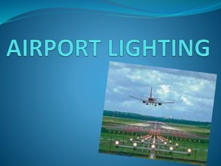
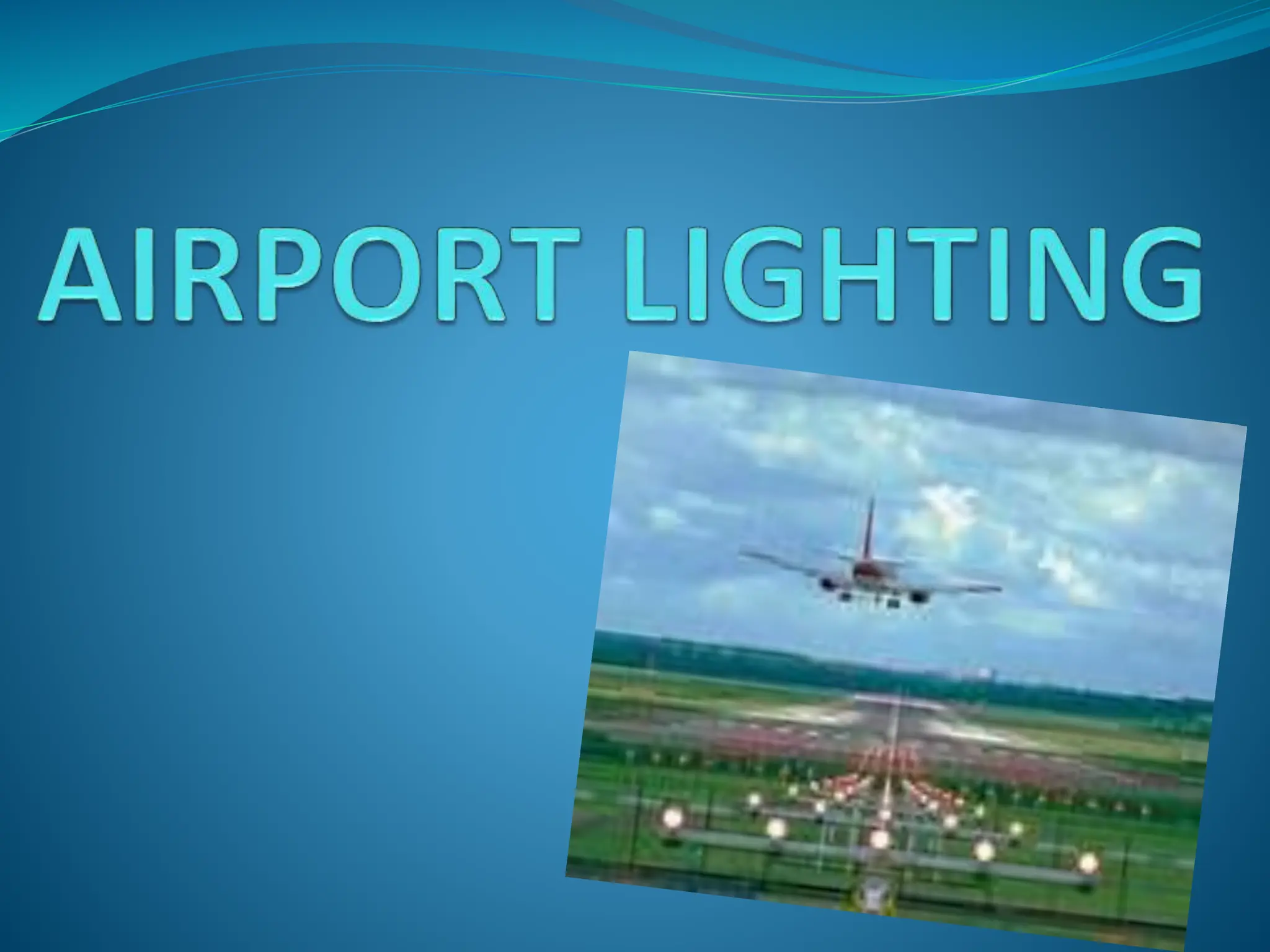
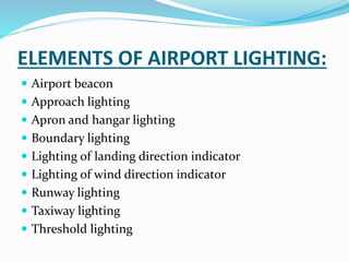


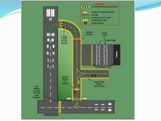
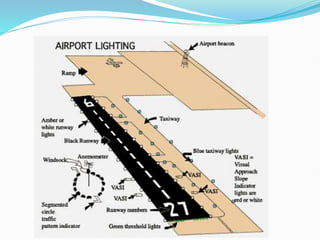
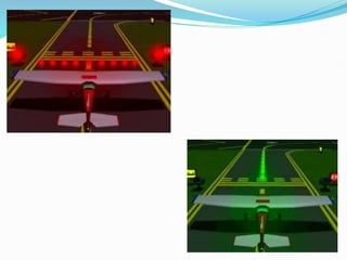
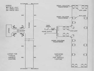


The document discusses factors that affect airport lighting and the various elements of airport lighting systems. It describes key components like airport beacons, approach lighting, apron and hangar lighting, boundary lighting, runway edge lights, taxiway lighting, and threshold lighting. The types, placement, and functions of different lights are explained to provide guidance to pilots for takeoffs and landings during nighttime and low visibility conditions. Standardization of lighting systems, maintenance, and emergency backup power are also covered.


