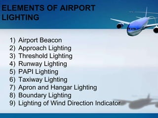
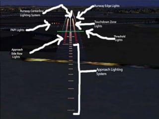
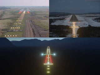
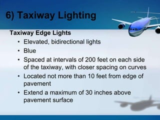
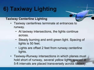
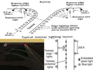
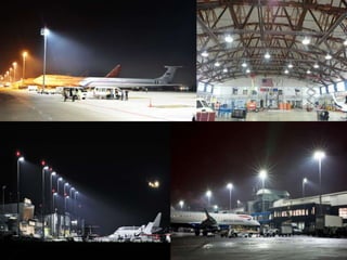
This document discusses the various lighting systems used at airports to guide pilots and provide safety. It describes 9 key elements: airport beacon, approach lighting, threshold lighting, runway lighting including edge and centerline lights, PAPI lights, taxiway lighting, apron and hangar lighting, boundary lighting, and lighting for the wind direction indicator. For each element, it provides details on the purpose, configuration, colors used, and specifications to achieve standardization and ensure pilot guidance.


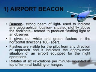
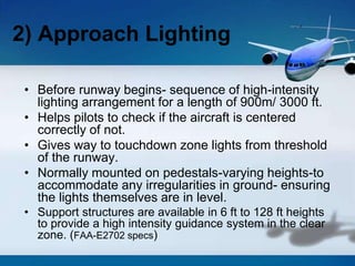
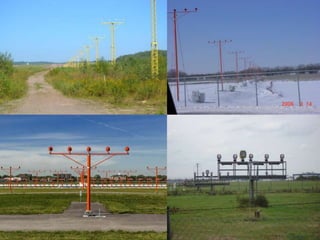
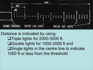
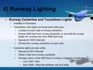
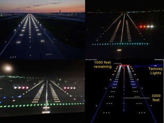


![Getting Started with Apache Spark: Big Data Made Simple [Free Meetup]](https://cdn.slidesharecdn.com/ss_thumbnails/apachesparkgettingstarted-260203175547-8361bcc3-thumbnail.jpg?width=640&height=640&fit=bounds)


