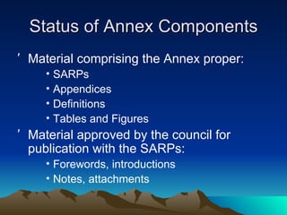
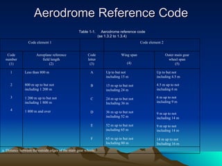
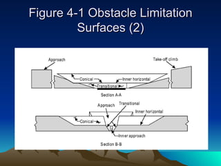
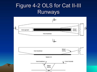
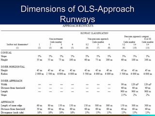
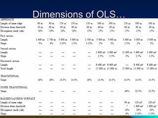
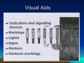
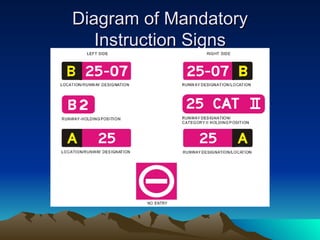
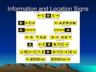
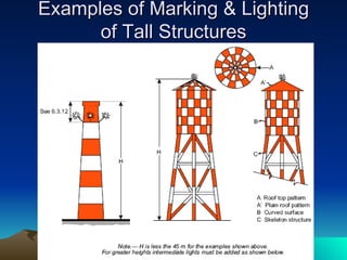
Annex 14 Aerodromes Volume 1 Aerodrome Design and Operations By:- Cheng Ling Perng
The Objectives Understanding the philosophy of ICAO’s Annex 14 SARP for Aerodromes Identify, explain and discuss the more important Standard And Recommended Practices (SARPs) of Annex 14
Methodology Classroom manual text review (referring to Annex 14 text & review accordingly)  Study of texts, tables, figures & charts Discussions on important topics and how to resolve the issues Technical visit to an aerodrome (if necessary)
Development of SARPs ICAO adopted Aerodrome SARPs in 1951 & designated it as Annex 14 Many amendments since 1951 1990, Annex 14 split into 2 volumes Vol. 1 - Aerodrome Design & Operations Vol. 2 - Heliports Signatories agree to abide by or to exceed the standards If signatories choose to differ, they must file a difference with ICAO
Annex 14 Amending Process A country submits an issue to ICAO If pertinent, ICAO forms a Project Team Research, risk analysis & impact assessments are done over a few years Brought before the aerodrome ICAO main meeting Draft and consultation Final amendments Ex. International Runway Friction Index (IRFI)
Annex 14 – Table of Contents Abbreviations and Symbols Manuals – related to this Annex Foreword Chapter 1 - General Chapter 2 – Aerodrome Data Chapter 3 – Physical Characteristics  Chapter 4 – Obstacle Restriction & Removal Chapter 5 – Visual Aids for Navigation
Annex 14 – Table of Contents Chapter 6 – Visual Aids for Denoting Obstacles Chapter 7 – Visual Aids for Denoting Restricted  Use Areas Chapter 8 – Electrical Systems Chapter 9 – Aerodrome operational services Chapter 10 – Aerodrome maintenance Appendices 1 to 6 Attachment A – Suppl. Guidance Material Attachment B – Obstacle Limitation Surface Index
Editorial Practices Standards:- light face roman Recommended practices:- light face italics Status of RPs:- prefix as  Recommendation Notes:-light face italics Status of Notes:- prefix as  Notes
Standard Any specification, the uniform application of which is recognized as necessary for the safety or regularity of international air navigation and to which Contracting States  will conform  in accordance with the Convention
Recommended Practice Any specification, the uniform application of which is recognized  as desirable  in the interest of safety, regularity or efficiency of international air navigational, and to which Contracting states  will endeavour  to conform in accordance to the Convention
SARPs Standards are identified by the verb < shall > and are  mandatory Recommended practices are identified by the verb < should > and are only  recommendations
Critical Aircraft The aeroplane identified from among the aeroplanes the aerodrome is intended to serve has having the most demanding operational requirements
Aeroplane reference Field Length The minimum field length required for take-off at maximum certificated take-off mass, sea level, standard atmospheric conditions, still air an zero runway slope, as shown in the appropriate aeroplane field manual
The First Premise: The Aerodrome Reference Code The aerodromes are coded according to the physical requirements of the critical aircraft The aerodrome facilities (or part of) must meet physical requirements of the critical aircraft
Motivation Understanding the rationale applied in the development of Annex 14 will help the aerodrome inspector/operator to be more consistent in their interpretation and application of SARPs It will be helpful for them to have a thorough knowledge of SARPs that are more difficult to understand
Methodology Formal presentation and review of SARPs Study of texts, tables, figures, graphs and charts Discussions on topics, of problems and solutions Technical visit of an aerodrome
Outline Part I Rationale Part II Physical Characteristics & OLS Part III Visual Aids and other SARPs
Rationale Part I
Part I Outline Development of SARPs Amending Process Annex 14 Table of Contents Aerodrome Coding Concept
Status of Annex Components Material comprising the Annex proper: SARPs Appendices Definitions Tables and Figures Material approved by the council for publication with the SARPs: Forewords, introductions Notes, attachments
The Aerodrome Coding Concept Based on two premises Aerodrome reference code Type of approach Example: 3C NP Designed as a planning tool Applied in reverse when aerodrome built
Aerodrome Reference Code Table 1-1. Aerodrome reference code (se 1.3.2 to 1.3.4) a. Distance between the outside edges of the main gear wheels. Up to but not including 4.5 m 4.5 m up to not including 6 m 6 m up to not including 9 m 9 m up to not including 14 m 9 m up to not including 14 m 14 m up to not Including 16 m Up to but not including 15 m 15 m up to but not including 24 m 24 m up to but not   Including 36 m 36 m up to but not including 52 m 52 m up to but not including 65 m 65 m up to but not Including 80 m  A B C D E F Less than 800 m  800 m up to but not including 1 200 m 1 200 m up to but not including 1 800 m 1 800 m and over 1 2 3 4 Outer main gear wheel span (5) Wing span (4) Code letter (3) Aeroplane reference field length (2) Code number (1) Code element 2 Code element 1
Non-Instrument Runway (NI) A runway intended for the operation of aircraft using visual approach procedures
Non-Precision Runway (NP) An instrument runway served by visual aids and a non-visual aid providing at least lateral guidance adequate for a straight-in approach
Precision Runway (P) Category I An instrument runway served by ILS and/or MLS and visual aids intended for operations with a decision height not lower than 60m (200 ft) and either a visibility not less than 800 m or a runway visual range (RVR) not less than 550 m
Precision Runway (P) Category I Lateral and vertical guidance Down to 60 m (DH) Operating visibility not less than 880 m or RVR 550 m Most common of P runways
Precision Runway (P) Cat II - III Same as Cat I except Cat II has DH down to 30 m (100 ft) with visibility not less than RVR 350 m Same as Cat I except Cat III has DH and visibility from an RVR of 200 m (600 ft) down to no visual range limitations
The Second Premise: The Type of Approach  The SARPs translate the combination of the Aerodrome Reference Code and the type of approach procedure available for the runway (Ex. 3C NP) into specific aerodrome physical requirements The safety margin is increased as the approach minima is lowered
Review What differentiates a non-instrument runway from a non-precision runway? What two factors establish the rationale behind the SARPs? Aerodrome reference codes are based on two elements.  What are they? How do SARPs change with lower approach minima?
Physical Characteristics and Obstacle Limitation Surfaces  (OLS) Part II
Part II Outline Obstacle Limitation Surfaces (OLS) Displaced Threshold The strip and the inner edge Stopway Runway end safety area (RESA) Clearway Declared distances
Runway Characteristics Primary runway should be adequate to meet operational requirements of critical aircraft Length of runway corrected for elevation, temperature, slope, humidity and surface Length or runway need not be for maximum mass operations of critical aircraft Similar rationale for secondary runway
Runway Strip Defined in Annex 14 A defined area including the runway and stopway, if provided, intended: To reduce the risk of damage to aircraft running off a runway ; and To protect aircraft flying over it during take-off or landing operations
Graded Area Not defined in Annex 14 Included in the strip Intended to serve in the event of an aeroplane running off the runway Obstacle free and free of ditches, holes  Supportive of vehicles and aircraft
Obstacle Limitation Surfaces (OLS) Purpose To define the airspace around aerodromes to be maintained free of  obstacles so as to permit safe aerodrome operations and to prevent the growth of obstacles around aerodromes
Obstacles Limitation Surfaces (OLS) Requirements For NI, NP & P runways (4.2) Inner horizontal surface Conical surface Approach surface Transitional surfaces
Figure 4-1 Obstacle Limitation Surfaces (1)
Figure 4-1 Obstacle Limitation Surfaces (2)
Obstacle… For Cat II-III runways (4.2) Conical surface  Inner horizontal surface Approach surface & inner approach surface Transitional surface Inner transitional surface Balked landing surface
Figure 4-2 OLS for Cat II-III Runways
Dimensions of OLS-Approach Runways
Dimensions of OLS…
Dimensions of OLS for Runways Meant for Take-Off RUNWAYS MEANT FOR TAKE-OFF All dimensions are measured horizontally unless specified otherwise. The take-off climb surface starts at the end of the clearway if the clearway length exceeds the specified distance. 1 800 m when the intended track includes changes of  heading greater than 15 for operations conducted in IMC, VMC by night. See 4.2.24 and 4.2.26. 180 m 60 m 12.5% 1 200 m 1 800 m 15 000 m 2% 80 m 60 m 10% 580 m 2 500 m 4% 60 m 30 m 10% 380 m 1 600 m 5% TAKE-OFF CLIMB Length of inner edge Distance from runway end Divergence (each side) Final width Length Slope 3 or 4 (4) Code number 2 (3) 1 (2) Surface and dimensions (1)
Displaced Threshold Defined in Annex 14: A threshold not located at the extremity of a runway Provides obstacle free approach slope May be used for take-off Affects LDA Temporary or permanent Specific markings
Diagram of Displaced Threshold Markings
Relocation of a Threshold Not defined in Annex 14 Pre-threshold usually not suitable for a/c Affects all declared distances Specific markings: chevrons (7.2), closed runway markings (7.1)
The Strip & the Inner Edge Strip provides protection for a/c on the ground & in flight Usually slope of OLS starts at outer edge of strip In a displaced threshold, the inner edge of OLS is at the point of displacement The inner edge is the point at which the approach surface commences So, strip end & inner edge are not always co-located
Questions If a runway is 1000 m long, how long is the strip? Runway 06/24 is 2500 m long.  Threshold of 06 is displaces 300 m and the threshold of runway 24 is displaced 250 m.  How long is the strip? Where is the inner edge on runway 06?
Stopway Defined in annex 14 & explained (3.6) A defined rectangular area on the ground at the end of the take-off run available (TORA) prepared as a suitable area in which an a/c can be stopped in the case of an abandoned take-off Within the strip & has the width of the runway Included in ASDA Width equal to runway Expensive
Runway End Safety Area (RESA) Defined in Annex 14 & Explained (3.4) At each end of runway strip Purpose: to reduce the risk of damage to an aeroplane undershooting or overrunning the runway Not included in declared distances Minimum length: 90 m Width: twice that of runway
Clearway Defined in Annex 14 & explained (3.5) A defined area on the ground or water under the control of the appropriate authority, selected or prepared as a suitable area over which an aeroplane may make a portion of its initial climb to a specified height Commences at the end of TORA, may extend beyond the strip Included in TODA Length: not more than 50% of TORA Width: 75 m on each side of extended centre line Inexpensive & common
`Declared Dstances TORA & TODA TORA: Take-off run available.  The length of runway declared available and suitable for the ground run of an aeroplane taking-off TODA: Take-off distance available.  The length of the take-off run available (TORA) plus the length of the clearway, if provided
ASDA & LDA ASDA: Accelerate-stop distance available. The length of the take-off available (TODA) plus the length of the stopway, if provided LDA: Landing distance available.  The length of runway which is declared available and suitable for the ground run of an aeroplane landing.  LDA is TORA less any displacement of the threshold
Diagrams of Declared Distances
Exercise <<ABC International Airport>> Declared Distances
Declared Distances of  <<ABC International Airport>> Runway 09/27 is 200 m long Rwy 09: clearway 580 m, stopway 300m, displaced threshold 150 m Rwy 27: stopway 350 m, clearway 350 m What are the declared distances for this airport?
Runway Diagram of <<ABC International Airport>>
Declared distances 2000 2350 2350 2000 27 1850 2580 2300 2000 09 m m m m LDA TODA ASDA TORA RWY
End of Parts 1 and 2
Visual Aids and Other SARPs Part III
Outline of Part 3 Markings Lighting Signs Secondary power supply Fencing Maintenance Appendices and attachments
Visual Aids
Foreword The longest chapter in Annex 14 Visual aids increase in number and complexity as aerodrome code number increases and approach minima decreases The presentation will be centered on markings, lights and signs Visual aids require daily inspections and proper maintenance by specialized personnel
Markings Order of importance: P, NP, NI Colour of runway: white Colour of taxiway and a/c stands: yellow Outlining in black of white markings For night operations: reflective materials Markings: solid areas or series of longitudinal stripes
Runway Markings Rwy designation: two-digit, magnetic,  letter for parallel rwys (L,C,R) Runway Centre line Threshold markings Transverse stripe  Arrows Aiming point Touchdown zone Side stripe
Diagram of runway markings
Other markings Taxiway centre line, (de-icing, apron) Runway holding position Aircraft stand Apron safety lines and passenger safety lines Road holding position Mandatory instruction Information
Apron Safety Lines and Passenger Path Lines
Lights: General Comments Lights which may cause confusion Frangibility Surface lights Intensity and control Emergency lighting Aerodrome beacon Identification beacon Maintenance
Approach Lighting Systems Simple approach lighting system Precision approach lighting system Precision approach category I-II lighting system
Visual Approach Slope Indicators When: turbojet service, inadequate visual guidance, misleading ground information, obstacles, slope of runway or terrain Suitability for day and night operations Obstacle protection surface & slope of rwy T-V ASIS, AT-VASIS PAPI, APAPI Maintenance and calibration
Diagram of Visual Approach Slope Indicator Systems
Runway Lights Runway Threshold Lights (RIL) Runway edge lights: white, 60m spacing for instrument rwy and 100m for NI rwy Runway threshold lights: min. of 6, green Runway end lights: min. of 6, red Runway centre lights: Cat.II-III, for take-off Rwy tdz lights: Cat.II-III Stopway lights: red Figure 5-19, p.79
Other Lights Taxiway centre line ( on taxiway, on exit) Taxiway edge lights: blue Taxiway stop bars: red Runway guard lights: yellow, fig.5-23 p.86 Apron floodlighting Visual docking system Figure 5-20 p.80 Inspection and maintenance
Signs Purpose: to convey mandatory instructions, information on a specific location or destination and other information Characteristics: Frangible Clear of props & engine pods Rectangular Red for mandatory instructions Illuminated: instrument rwy/ cat. 3-4 NI rwy
Mandatory Signs White on red background Identifies a position not to proceed beyond unless authorized or cleared Runway designation Co-location with holding position markings No entry
Information Signs Black on yellow Includes direction, destination and runway exit signs Provided where there is an operational need
Location Signs Yellow on black Indicates location on an aerodrome Only sign which may be located with a mandatory instruction sign Outboard of a runway designation sign Where signs are combined to form an array, the individual signs are delineated by a black stripe
Diagram of Mandatory Instruction Signs
Information and Location Signs
 
Visual Aids for Denoting Obstacles Aim: reduce hazards to a/c by indicating the presence of obstacles (lights &/or markings) Responsibility: CAA, airport authority Sensitive areas: approach surfaces, climb surfaces, obstacle protection surfaces, airport vicinity Obstacles reported in Aerodrome Manual Colours: checkered pattern Orange & white or red & white
Examples of Marking & Lighting of Tall Structures
Lighting of Buildings
Closed Runway and Taxiway Markings Markings displayed for permanently closed and temporarily closed (RP) rwy & twy: X Location: at each end or portion and interval between markings <300m Colour: white for rwy, yellow for twy Permanently closed rwy & twy: markings to be obliterated Closed rwy & twy: lighting off
Closed Runway and Taxiway Markings
Unsuitable Pre-Threshold Area Condition: paved & > 60m Pre-threshold area: chevron markings
Unserviceable Areas Condition: any portion of rwy, twy, apron unfit for a/c movement but still possible for a/c to bypass area safely Markers: flags, cones, marker boards and red lights for night operations
Secondary Power Supply For medium & major aerodromes Facilities: signaling lamps, obstacle lights, approach, rwy, twy lighting, essential equipment Source of supply: same source but different substation and routing, or standby power units.  Testing of generators Switch-over time: 1 second to 2 minutes depending on runway category (NI, NP, P) Monitoring of visual aids
Fencing Aim: to prevent the entrance to the movement area of large animals and unauthorized persons Includes ducts, tunnels, sewers, overpass Patrols on perimeter road inside of fences Security lighting of fencing area
Maintenance A maintenance plan should be prepared: Short term Long term Preventive maintenance is less costly Pavements: daily inspections, special attention to cracks and friction Visual aids: daily inspections, maintenance often by specialized personnel, many SARPs aimed at lighting systems
Appendices and Attachments Appendices 1 to 6 : Mostly for engineers, land surveyors and technical personnel Attachment A Guidance material: very informative texts on 18 topics such as stopways, clearways, declared distances, strips, AFF, vehicle operations… Attachment B obstacle limitation surfaces diagram:  an overall view Index: where to look for information
Conclusion What have we learned?

Annex 14 ppt cheng

  • 1.
    Annex 14 AerodromesVolume 1 Aerodrome Design and Operations By:- Cheng Ling Perng
  • 2.
    The Objectives Understandingthe philosophy of ICAO’s Annex 14 SARP for Aerodromes Identify, explain and discuss the more important Standard And Recommended Practices (SARPs) of Annex 14
  • 3.
    Methodology Classroom manualtext review (referring to Annex 14 text & review accordingly) Study of texts, tables, figures & charts Discussions on important topics and how to resolve the issues Technical visit to an aerodrome (if necessary)
  • 4.
    Development of SARPsICAO adopted Aerodrome SARPs in 1951 & designated it as Annex 14 Many amendments since 1951 1990, Annex 14 split into 2 volumes Vol. 1 - Aerodrome Design & Operations Vol. 2 - Heliports Signatories agree to abide by or to exceed the standards If signatories choose to differ, they must file a difference with ICAO
  • 5.
    Annex 14 AmendingProcess A country submits an issue to ICAO If pertinent, ICAO forms a Project Team Research, risk analysis & impact assessments are done over a few years Brought before the aerodrome ICAO main meeting Draft and consultation Final amendments Ex. International Runway Friction Index (IRFI)
  • 6.
    Annex 14 –Table of Contents Abbreviations and Symbols Manuals – related to this Annex Foreword Chapter 1 - General Chapter 2 – Aerodrome Data Chapter 3 – Physical Characteristics Chapter 4 – Obstacle Restriction & Removal Chapter 5 – Visual Aids for Navigation
  • 7.
    Annex 14 –Table of Contents Chapter 6 – Visual Aids for Denoting Obstacles Chapter 7 – Visual Aids for Denoting Restricted Use Areas Chapter 8 – Electrical Systems Chapter 9 – Aerodrome operational services Chapter 10 – Aerodrome maintenance Appendices 1 to 6 Attachment A – Suppl. Guidance Material Attachment B – Obstacle Limitation Surface Index
  • 8.
    Editorial Practices Standards:-light face roman Recommended practices:- light face italics Status of RPs:- prefix as Recommendation Notes:-light face italics Status of Notes:- prefix as Notes
  • 9.
    Standard Any specification,the uniform application of which is recognized as necessary for the safety or regularity of international air navigation and to which Contracting States will conform in accordance with the Convention
  • 10.
    Recommended Practice Anyspecification, the uniform application of which is recognized as desirable in the interest of safety, regularity or efficiency of international air navigational, and to which Contracting states will endeavour to conform in accordance to the Convention
  • 11.
    SARPs Standards areidentified by the verb < shall > and are mandatory Recommended practices are identified by the verb < should > and are only recommendations
  • 12.
    Critical Aircraft Theaeroplane identified from among the aeroplanes the aerodrome is intended to serve has having the most demanding operational requirements
  • 13.
    Aeroplane reference FieldLength The minimum field length required for take-off at maximum certificated take-off mass, sea level, standard atmospheric conditions, still air an zero runway slope, as shown in the appropriate aeroplane field manual
  • 14.
    The First Premise:The Aerodrome Reference Code The aerodromes are coded according to the physical requirements of the critical aircraft The aerodrome facilities (or part of) must meet physical requirements of the critical aircraft
  • 15.
    Motivation Understanding therationale applied in the development of Annex 14 will help the aerodrome inspector/operator to be more consistent in their interpretation and application of SARPs It will be helpful for them to have a thorough knowledge of SARPs that are more difficult to understand
  • 16.
    Methodology Formal presentationand review of SARPs Study of texts, tables, figures, graphs and charts Discussions on topics, of problems and solutions Technical visit of an aerodrome
  • 17.
    Outline Part IRationale Part II Physical Characteristics & OLS Part III Visual Aids and other SARPs
  • 18.
  • 19.
    Part I OutlineDevelopment of SARPs Amending Process Annex 14 Table of Contents Aerodrome Coding Concept
  • 20.
    Status of AnnexComponents Material comprising the Annex proper: SARPs Appendices Definitions Tables and Figures Material approved by the council for publication with the SARPs: Forewords, introductions Notes, attachments
  • 21.
    The Aerodrome CodingConcept Based on two premises Aerodrome reference code Type of approach Example: 3C NP Designed as a planning tool Applied in reverse when aerodrome built
  • 22.
    Aerodrome Reference CodeTable 1-1. Aerodrome reference code (se 1.3.2 to 1.3.4) a. Distance between the outside edges of the main gear wheels. Up to but not including 4.5 m 4.5 m up to not including 6 m 6 m up to not including 9 m 9 m up to not including 14 m 9 m up to not including 14 m 14 m up to not Including 16 m Up to but not including 15 m 15 m up to but not including 24 m 24 m up to but not Including 36 m 36 m up to but not including 52 m 52 m up to but not including 65 m 65 m up to but not Including 80 m A B C D E F Less than 800 m 800 m up to but not including 1 200 m 1 200 m up to but not including 1 800 m 1 800 m and over 1 2 3 4 Outer main gear wheel span (5) Wing span (4) Code letter (3) Aeroplane reference field length (2) Code number (1) Code element 2 Code element 1
  • 23.
    Non-Instrument Runway (NI)A runway intended for the operation of aircraft using visual approach procedures
  • 24.
    Non-Precision Runway (NP)An instrument runway served by visual aids and a non-visual aid providing at least lateral guidance adequate for a straight-in approach
  • 25.
    Precision Runway (P)Category I An instrument runway served by ILS and/or MLS and visual aids intended for operations with a decision height not lower than 60m (200 ft) and either a visibility not less than 800 m or a runway visual range (RVR) not less than 550 m
  • 26.
    Precision Runway (P)Category I Lateral and vertical guidance Down to 60 m (DH) Operating visibility not less than 880 m or RVR 550 m Most common of P runways
  • 27.
    Precision Runway (P)Cat II - III Same as Cat I except Cat II has DH down to 30 m (100 ft) with visibility not less than RVR 350 m Same as Cat I except Cat III has DH and visibility from an RVR of 200 m (600 ft) down to no visual range limitations
  • 28.
    The Second Premise:The Type of Approach The SARPs translate the combination of the Aerodrome Reference Code and the type of approach procedure available for the runway (Ex. 3C NP) into specific aerodrome physical requirements The safety margin is increased as the approach minima is lowered
  • 29.
    Review What differentiatesa non-instrument runway from a non-precision runway? What two factors establish the rationale behind the SARPs? Aerodrome reference codes are based on two elements. What are they? How do SARPs change with lower approach minima?
  • 30.
    Physical Characteristics andObstacle Limitation Surfaces (OLS) Part II
  • 31.
    Part II OutlineObstacle Limitation Surfaces (OLS) Displaced Threshold The strip and the inner edge Stopway Runway end safety area (RESA) Clearway Declared distances
  • 32.
    Runway Characteristics Primaryrunway should be adequate to meet operational requirements of critical aircraft Length of runway corrected for elevation, temperature, slope, humidity and surface Length or runway need not be for maximum mass operations of critical aircraft Similar rationale for secondary runway
  • 33.
    Runway Strip Definedin Annex 14 A defined area including the runway and stopway, if provided, intended: To reduce the risk of damage to aircraft running off a runway ; and To protect aircraft flying over it during take-off or landing operations
  • 34.
    Graded Area Notdefined in Annex 14 Included in the strip Intended to serve in the event of an aeroplane running off the runway Obstacle free and free of ditches, holes Supportive of vehicles and aircraft
  • 35.
    Obstacle Limitation Surfaces(OLS) Purpose To define the airspace around aerodromes to be maintained free of obstacles so as to permit safe aerodrome operations and to prevent the growth of obstacles around aerodromes
  • 36.
    Obstacles Limitation Surfaces(OLS) Requirements For NI, NP & P runways (4.2) Inner horizontal surface Conical surface Approach surface Transitional surfaces
  • 37.
    Figure 4-1 ObstacleLimitation Surfaces (1)
  • 38.
    Figure 4-1 ObstacleLimitation Surfaces (2)
  • 39.
    Obstacle… For CatII-III runways (4.2) Conical surface Inner horizontal surface Approach surface & inner approach surface Transitional surface Inner transitional surface Balked landing surface
  • 40.
    Figure 4-2 OLSfor Cat II-III Runways
  • 41.
  • 42.
  • 43.
    Dimensions of OLSfor Runways Meant for Take-Off RUNWAYS MEANT FOR TAKE-OFF All dimensions are measured horizontally unless specified otherwise. The take-off climb surface starts at the end of the clearway if the clearway length exceeds the specified distance. 1 800 m when the intended track includes changes of heading greater than 15 for operations conducted in IMC, VMC by night. See 4.2.24 and 4.2.26. 180 m 60 m 12.5% 1 200 m 1 800 m 15 000 m 2% 80 m 60 m 10% 580 m 2 500 m 4% 60 m 30 m 10% 380 m 1 600 m 5% TAKE-OFF CLIMB Length of inner edge Distance from runway end Divergence (each side) Final width Length Slope 3 or 4 (4) Code number 2 (3) 1 (2) Surface and dimensions (1)
  • 44.
    Displaced Threshold Definedin Annex 14: A threshold not located at the extremity of a runway Provides obstacle free approach slope May be used for take-off Affects LDA Temporary or permanent Specific markings
  • 45.
    Diagram of DisplacedThreshold Markings
  • 46.
    Relocation of aThreshold Not defined in Annex 14 Pre-threshold usually not suitable for a/c Affects all declared distances Specific markings: chevrons (7.2), closed runway markings (7.1)
  • 47.
    The Strip &the Inner Edge Strip provides protection for a/c on the ground & in flight Usually slope of OLS starts at outer edge of strip In a displaced threshold, the inner edge of OLS is at the point of displacement The inner edge is the point at which the approach surface commences So, strip end & inner edge are not always co-located
  • 48.
    Questions If arunway is 1000 m long, how long is the strip? Runway 06/24 is 2500 m long. Threshold of 06 is displaces 300 m and the threshold of runway 24 is displaced 250 m. How long is the strip? Where is the inner edge on runway 06?
  • 49.
    Stopway Defined inannex 14 & explained (3.6) A defined rectangular area on the ground at the end of the take-off run available (TORA) prepared as a suitable area in which an a/c can be stopped in the case of an abandoned take-off Within the strip & has the width of the runway Included in ASDA Width equal to runway Expensive
  • 50.
    Runway End SafetyArea (RESA) Defined in Annex 14 & Explained (3.4) At each end of runway strip Purpose: to reduce the risk of damage to an aeroplane undershooting or overrunning the runway Not included in declared distances Minimum length: 90 m Width: twice that of runway
  • 51.
    Clearway Defined inAnnex 14 & explained (3.5) A defined area on the ground or water under the control of the appropriate authority, selected or prepared as a suitable area over which an aeroplane may make a portion of its initial climb to a specified height Commences at the end of TORA, may extend beyond the strip Included in TODA Length: not more than 50% of TORA Width: 75 m on each side of extended centre line Inexpensive & common
  • 52.
    `Declared Dstances TORA& TODA TORA: Take-off run available. The length of runway declared available and suitable for the ground run of an aeroplane taking-off TODA: Take-off distance available. The length of the take-off run available (TORA) plus the length of the clearway, if provided
  • 53.
    ASDA & LDAASDA: Accelerate-stop distance available. The length of the take-off available (TODA) plus the length of the stopway, if provided LDA: Landing distance available. The length of runway which is declared available and suitable for the ground run of an aeroplane landing. LDA is TORA less any displacement of the threshold
  • 54.
  • 55.
    Exercise <<ABC InternationalAirport>> Declared Distances
  • 56.
    Declared Distances of <<ABC International Airport>> Runway 09/27 is 200 m long Rwy 09: clearway 580 m, stopway 300m, displaced threshold 150 m Rwy 27: stopway 350 m, clearway 350 m What are the declared distances for this airport?
  • 57.
    Runway Diagram of<<ABC International Airport>>
  • 58.
    Declared distances 20002350 2350 2000 27 1850 2580 2300 2000 09 m m m m LDA TODA ASDA TORA RWY
  • 59.
    End of Parts1 and 2
  • 60.
    Visual Aids andOther SARPs Part III
  • 61.
    Outline of Part3 Markings Lighting Signs Secondary power supply Fencing Maintenance Appendices and attachments
  • 62.
  • 63.
    Foreword The longestchapter in Annex 14 Visual aids increase in number and complexity as aerodrome code number increases and approach minima decreases The presentation will be centered on markings, lights and signs Visual aids require daily inspections and proper maintenance by specialized personnel
  • 64.
    Markings Order ofimportance: P, NP, NI Colour of runway: white Colour of taxiway and a/c stands: yellow Outlining in black of white markings For night operations: reflective materials Markings: solid areas or series of longitudinal stripes
  • 65.
    Runway Markings Rwydesignation: two-digit, magnetic, letter for parallel rwys (L,C,R) Runway Centre line Threshold markings Transverse stripe Arrows Aiming point Touchdown zone Side stripe
  • 66.
  • 67.
    Other markings Taxiwaycentre line, (de-icing, apron) Runway holding position Aircraft stand Apron safety lines and passenger safety lines Road holding position Mandatory instruction Information
  • 68.
    Apron Safety Linesand Passenger Path Lines
  • 69.
    Lights: General CommentsLights which may cause confusion Frangibility Surface lights Intensity and control Emergency lighting Aerodrome beacon Identification beacon Maintenance
  • 70.
    Approach Lighting SystemsSimple approach lighting system Precision approach lighting system Precision approach category I-II lighting system
  • 71.
    Visual Approach SlopeIndicators When: turbojet service, inadequate visual guidance, misleading ground information, obstacles, slope of runway or terrain Suitability for day and night operations Obstacle protection surface & slope of rwy T-V ASIS, AT-VASIS PAPI, APAPI Maintenance and calibration
  • 72.
    Diagram of VisualApproach Slope Indicator Systems
  • 73.
    Runway Lights RunwayThreshold Lights (RIL) Runway edge lights: white, 60m spacing for instrument rwy and 100m for NI rwy Runway threshold lights: min. of 6, green Runway end lights: min. of 6, red Runway centre lights: Cat.II-III, for take-off Rwy tdz lights: Cat.II-III Stopway lights: red Figure 5-19, p.79
  • 74.
    Other Lights Taxiwaycentre line ( on taxiway, on exit) Taxiway edge lights: blue Taxiway stop bars: red Runway guard lights: yellow, fig.5-23 p.86 Apron floodlighting Visual docking system Figure 5-20 p.80 Inspection and maintenance
  • 75.
    Signs Purpose: toconvey mandatory instructions, information on a specific location or destination and other information Characteristics: Frangible Clear of props & engine pods Rectangular Red for mandatory instructions Illuminated: instrument rwy/ cat. 3-4 NI rwy
  • 76.
    Mandatory Signs Whiteon red background Identifies a position not to proceed beyond unless authorized or cleared Runway designation Co-location with holding position markings No entry
  • 77.
    Information Signs Blackon yellow Includes direction, destination and runway exit signs Provided where there is an operational need
  • 78.
    Location Signs Yellowon black Indicates location on an aerodrome Only sign which may be located with a mandatory instruction sign Outboard of a runway designation sign Where signs are combined to form an array, the individual signs are delineated by a black stripe
  • 79.
    Diagram of MandatoryInstruction Signs
  • 80.
  • 81.
  • 82.
    Visual Aids forDenoting Obstacles Aim: reduce hazards to a/c by indicating the presence of obstacles (lights &/or markings) Responsibility: CAA, airport authority Sensitive areas: approach surfaces, climb surfaces, obstacle protection surfaces, airport vicinity Obstacles reported in Aerodrome Manual Colours: checkered pattern Orange & white or red & white
  • 83.
    Examples of Marking& Lighting of Tall Structures
  • 84.
  • 85.
    Closed Runway andTaxiway Markings Markings displayed for permanently closed and temporarily closed (RP) rwy & twy: X Location: at each end or portion and interval between markings <300m Colour: white for rwy, yellow for twy Permanently closed rwy & twy: markings to be obliterated Closed rwy & twy: lighting off
  • 86.
    Closed Runway andTaxiway Markings
  • 87.
    Unsuitable Pre-Threshold AreaCondition: paved & > 60m Pre-threshold area: chevron markings
  • 88.
    Unserviceable Areas Condition:any portion of rwy, twy, apron unfit for a/c movement but still possible for a/c to bypass area safely Markers: flags, cones, marker boards and red lights for night operations
  • 89.
    Secondary Power SupplyFor medium & major aerodromes Facilities: signaling lamps, obstacle lights, approach, rwy, twy lighting, essential equipment Source of supply: same source but different substation and routing, or standby power units. Testing of generators Switch-over time: 1 second to 2 minutes depending on runway category (NI, NP, P) Monitoring of visual aids
  • 90.
    Fencing Aim: toprevent the entrance to the movement area of large animals and unauthorized persons Includes ducts, tunnels, sewers, overpass Patrols on perimeter road inside of fences Security lighting of fencing area
  • 91.
    Maintenance A maintenanceplan should be prepared: Short term Long term Preventive maintenance is less costly Pavements: daily inspections, special attention to cracks and friction Visual aids: daily inspections, maintenance often by specialized personnel, many SARPs aimed at lighting systems
  • 92.
    Appendices and AttachmentsAppendices 1 to 6 : Mostly for engineers, land surveyors and technical personnel Attachment A Guidance material: very informative texts on 18 topics such as stopways, clearways, declared distances, strips, AFF, vehicle operations… Attachment B obstacle limitation surfaces diagram: an overall view Index: where to look for information
  • 93.