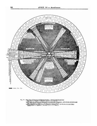
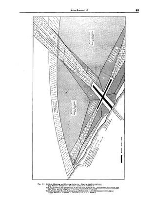
This document is the 1st edition of Annex 14 to the Convention on International Civil Aviation, which establishes international standards and recommended practices for aerodromes. It was adopted in 1951 and became effective on November 1st of that year. The annex applies to aerodromes used by international air services as well as other aerodromes used for international air navigation. It contains specifications for aerodrome physical characteristics, visual ground aids, obstruction marking, and other facilities to help ensure safety and regularity of operations at aerodromes worldwide.


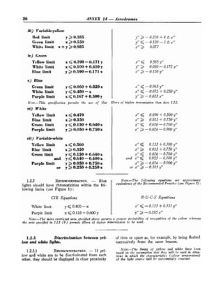
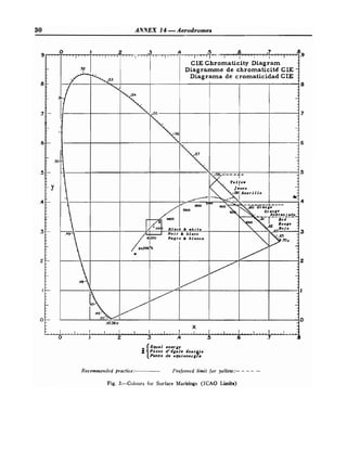


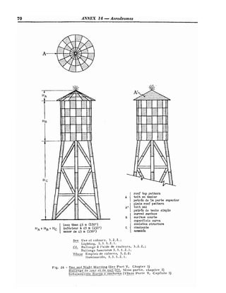
![54 ANNEX 14 -Aerodromes
2
.
2
.
1
.
2
.
1 Location.
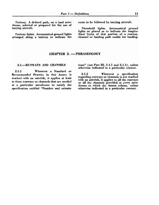
2
.
2
.
1
.
2
.
1
.
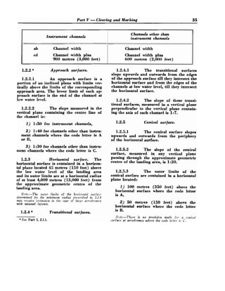
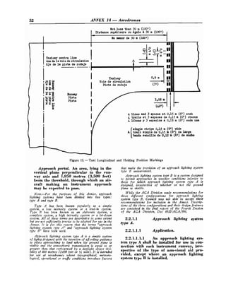
1 When used, angleof-ap-
proach lights shall be placed outside but
close to the edge of the runway. If one angle-
of-approach light only is provided, it shall
be installed on the left-hand side of the run-
way as viewed from an aircraft approaching
to land.
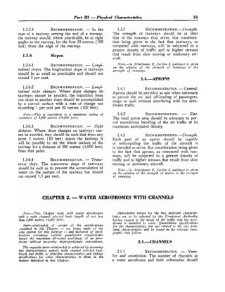
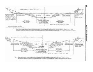
2.2.1.2.1.2 RECOMMENDATION.
- The
longitudinal location of the angle-of-approach
lights should be:
i) at a point between 60 metres (200 feet)
and 90 metres (300 feet) measured inwards
from the runway threshold, if not intended
for simultaneous use with an electronic ap-
proach aid, or
ii) at a point whi& will ensure that the
lower edge of the green beam will coincide
with the glide path as defined by the electronic
aid, if intended for simultaneous use with an
electronic approach aid.
2
.
2
.
1
.
2
.
2 Characteristics,
2
.
2
.
1
.
2
.
2
.
1 The angle-of-approachlight
shall produce three contiguous beams of
coloured light with a sharp change of colour
at the boundaries between beams. The
lowest beam shall be red with a spread in the
vertical plane of not less than 3 degrees. The
middle beam shall be green with a spread in
the vertical plane of 2 degrees. The upper
beam shall be yellow with a spread in the
vertical plane of not less than 6 degrees. The
spread of any beam in the horizontal plane
shall be not less than 12 degrees and the
centre of the beam shall be so orientated in
azimuth as to provide the best possible
guidance for a pilot approaching to land.
The intensity of the light within the angles
specified above shall not be less than 200
candles for any colour. The light shall emit
flashes of equal duration, at a frequency of
30 to 60 per minuta, the duration of the
flashes being longer than the intervening
dark periods.
2.2.1.2.2.2 RECOMMENDATION.
- In the
case of angle-of-approach lights intended for use
with an electronic approach aid, the lower edge
of the green beam should coincide with the glide
path of the electronic approach aid. In the case
of angle-of-approach lights not intended for use
with an electronic approach aid, the angle of ele-
vation of the centre of the green beam should be
between the limits of 3% degrees and 4%
degrees above the horizontal. I
f two angle-of-ap
proach lights are used, the elevation of the green
beams should be the same. At all times, however,
the low limit of the green beam should provide
guidance giving adequate clearance above all
obstructions on the approach path.
2
.
2
.
2 Runway lighting.
2
.
2
.
2
.
1 Runway lights.
2
.
2
.
2
.
1
.
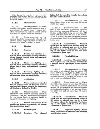
1 Application. Runway lights
shall be provided on all runways intended for
use at night.
2
.
2
.
2
.
1
.
2 Location.
2
.
2
.
2
.
1
.
2
.
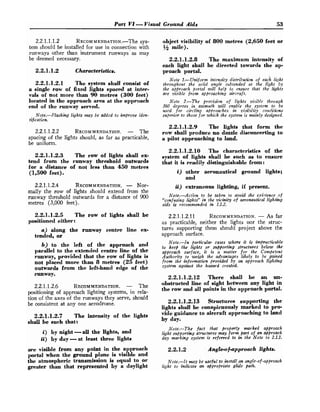
1 Runway lights shall be
placed along the full length of the runway,
between the threshold lights, and shall be in
two straight lines parallel to and equidistant
from the centre line.
a) Where the width of the rectangular area
intended for use as a runway is 45 metres
(150 feet) or less, the lines should either be
placed along the edges of the area or outside
the edges a distance of not more than 4.5 metres
(15 feet].
b ) Where the width of the rectangular area
exceeds 45 metres (150 feet) the distance be-
tween the rows of lights should not be less than
45 metres (150 feet) and should not be greater
than the width o
f the rectangular area plus
4.5 metres (15 feet) on either side.
Note.-In the case of instrument runways it is
preferable not to exceed o spacang of 70 metres (230
feet) between the rows of lights.
c j The lights should be uniformly spaced
in rows at intervals of not more than 60 metres
(200 feet) for instrument runways and at in-
tervals of not more than 100 metres (330 feet)
for all other runways. The lights on opposite
sides of the runway axis should be on lines at
right angles to that axis. At intersections of
runways, lights may be spaced irregularly or
omitted.](https://image.slidesharecdn.com/unit4reference-220623175545-1aa66b41/85/unit-4-reference-pdf-55-320.jpg)

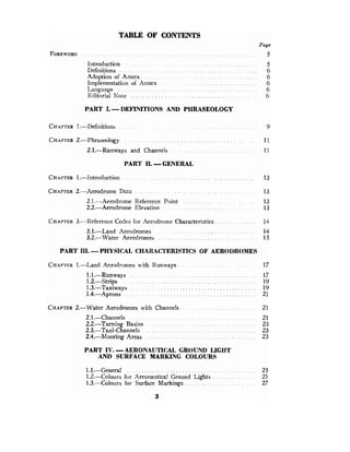
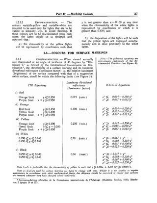
![74 ANNEX 14 -Aerodromes
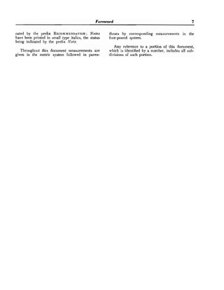
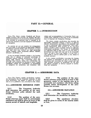
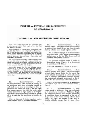
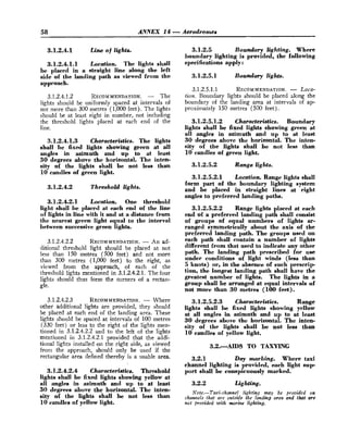
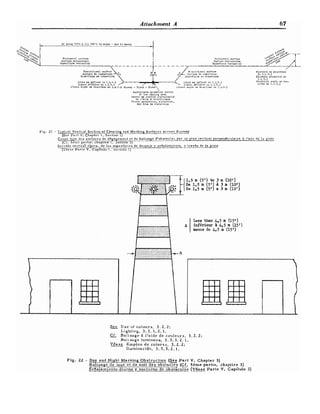
4.-MAIN RUNWAY O R CHANNEL BASIC
AND ACTUAL LENGTH
It will be ]toted that the princil~le underlying the
Recommendations (Part 111, Chapters 1 and 2) con-
cerning the acttlal lengths of runways or channels is the
same both for new and for existing aerodromes. The
Competent Authority first selects a main runway or
c l ~ a ~ ~ n e l
basic length to suit the requirements of the
trafic that the aerodrome is intended to serve. Then, by
adding any additional length necessary to take into
account density altitude and slope, if ally, he arrives at
the minimum actual length needed for the main run-
way or the main channel. In the case of an existing
For this reason it is always preferable to add correc-
tions to a wisely selected main runway or channel basic
length than to subtract "corrections" from the actual
letigth of a main runway or channel the origin of which
is in no way connected with current or future civil air
traffic requirements.
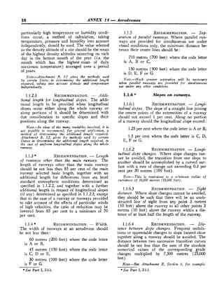
5.-RUNWAY OR C H A N N E L LENGTH
CORRECTIONS
5.1.-Additiolaal runzeaay or channel length
to be allozued for diflererrces from sea level
standurd atlnospheric conditions
~erodrome,the Competent Authority has onIy to compare
this required length with the existing length of the main
As stated in Part 111, Chapters 1 and 2, the accepted
~ncthod of calculating density altitude allowance may
runway or channel in order to determine whether ex-
tension is r~ecessaryor not. Ttie reverse process of sub-
not prove adequate in the case of aerodrome sites subject
tracting "corrections" for density altitude and longitu- to pr?rticularly higll temperature and high relative
dinal slope (if any) from the actual length of the main
humidity, particularly if the aerodrome is intended to
runway or channel at an existing aerodrome, in order serve turbo-jet engined aircraft.
to obtain the basic length. is nit prescribed for the
following reasons : To take care of such special cases, certain States
correct the runway or channel basic length selected for
a) there is no internationally accepted method of temperature and in the manner in&-
ca~culating the corrections to be made for specific =ated in the following extracts from official documents:
lcngitudinal slopes ;
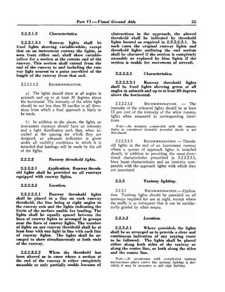
United States practice.-Altitude correction - Basic slopes on runways, it has not yet proved possible to
length to be increased by 7 per cent per 300 metres ~~roduce
an internationally accepted method of deter-
(1,000 feet) of elevation above sea level. mining appropriate allowances.
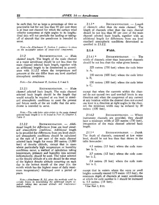
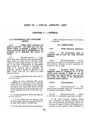
b) the actual length of the inain runway or channel Fvc~zclt pn~ctice.
-Additional lel~gth for altitude :
at 11 existing aerodrome may be greater or less than 5 per cent of the basic length per 300 metres (1,000
ihat required for the traffic that it is intended to serve feet) above sea level.
both now and in the future. An attempt to use a basic
length arrived at by subtracting "corrections" for Further additional length for temperature: variable
density altitude and slope from the actual length is percentages according to the difference between the
likely to lead to the developn~entof either an uneco- mean of the highest daily temperatures in the hottest
nomically large aerodrome or an aerodrome that is month of the year and the standard temperature of
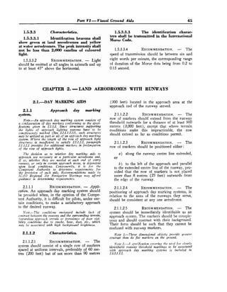
too small for the traffic it is intended to serve. 15°C (59"F), as shown in the following table:
Temperature correction -Altitude corrected length
to be further increased by 0.5 per cent for each degree The following extracts from official documents will
Fahrenheit w,hich the ten~peratureof the hottest month afford useful guidance :
exceeds the standard temperature of the site.
5.2.-Addition01 run~uayletlgth to be allowed
for longitudinal slope
0
~
0
10
I
i 20
I
I 18 1 - 36
Difference
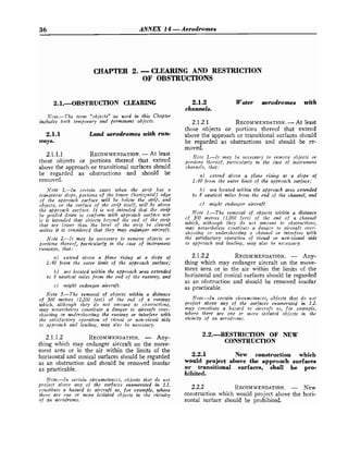
1) Fre~tch practice. -The additional length of a
runway should be calculated at the rate of 3.5 per cent
of the uncorrected length where the code letter is A,
30
54
Cent.
Fah.
Because of the wide variety of possible !olrgitudinal B, C, D, E,F or G if the average slope of the runway
20%
- - I -1 .- - -
I
.
-
-
-
-
I Percentage ! 0 1 5%
i ! I
10%](https://image.slidesharecdn.com/unit4reference-220623175545-1aa66b41/85/unit-4-reference-pdf-75-320.jpg)
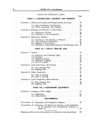
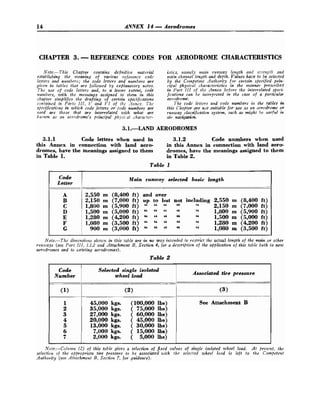
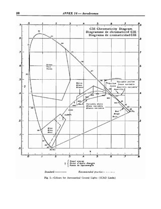
![Attachment B 75
reaches 1 per cent. Where the code letter is E, F or G,
tlte additional length ~l~orrltl
be 6 per cent of the
uncorrected length if the average slope reaches 1.5
per cent.
2) United Kirrgdorrr Bractice. -For average aircraft
under average operating conditions the unstick distance
is increased by apl~roximately 10 per cent for every
1" s runway is inclined above the horizontal.
3j Unifed Sfotes practicz. - The runway length
should be increased to correct for runway gradient at
tlte rate of 20 per cent of the length corrected for
(tensity altitude for each 1 per cent of effective runway
gradient. The effective runway gradient is determined
by dividing tlte maxilnuln difference in runway centre
line elevation by the total length of the runway.
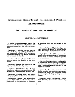
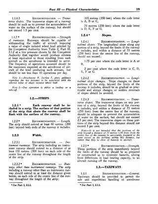
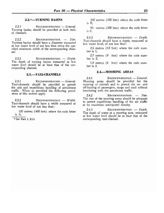
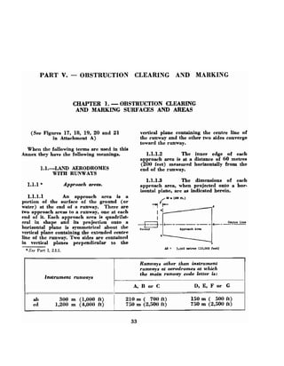
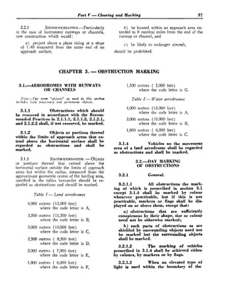
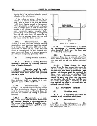
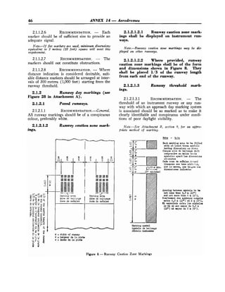
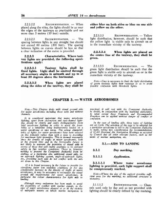
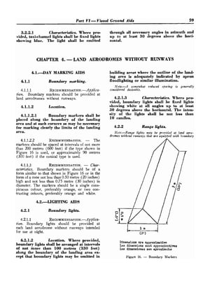
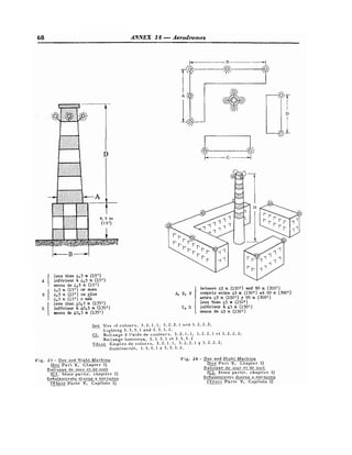
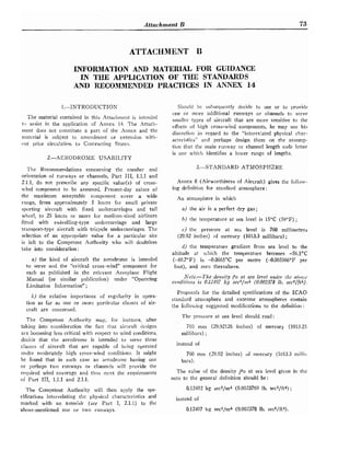
4.-DISTANCE BETWEEN SLOPE CHANGES
As an example of how the Recommendations contained
in Part 111, 1.1.6.4, is itltended to be applied, consider
the case illustrated in the following profile:
I I
Profile on centre line of runw:l)'
D should be at least
25,000 (Ix-y] + IY-z~) feet
being the absolute numeral value of x-y
1 being the absolute numeral value of y-z
Assuming x = + 0.01
y = - 0.005
z = + 0.005
Then Ix-yl = 0.015
ly-z 1 z 0.01
To comply with the specification, D sl~ouldbe not less
than 7,500 (0.015 -{- 0.01) metres, that is, 7,500x0.025 =
187.50 metres
or
25,000 (0.015 + 0.01) feet,
that is, 25,000 x 0.025 = 625 feet.
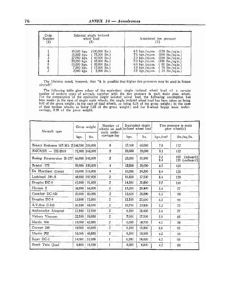
7.-RUNWAY STRENGTH
The AGA Division at its Third Session recommended
the associatioil of tire pressures with single isolated
wheel load as follows:](https://image.slidesharecdn.com/unit4reference-220623175545-1aa66b41/85/unit-4-reference-pdf-76-320.jpg)