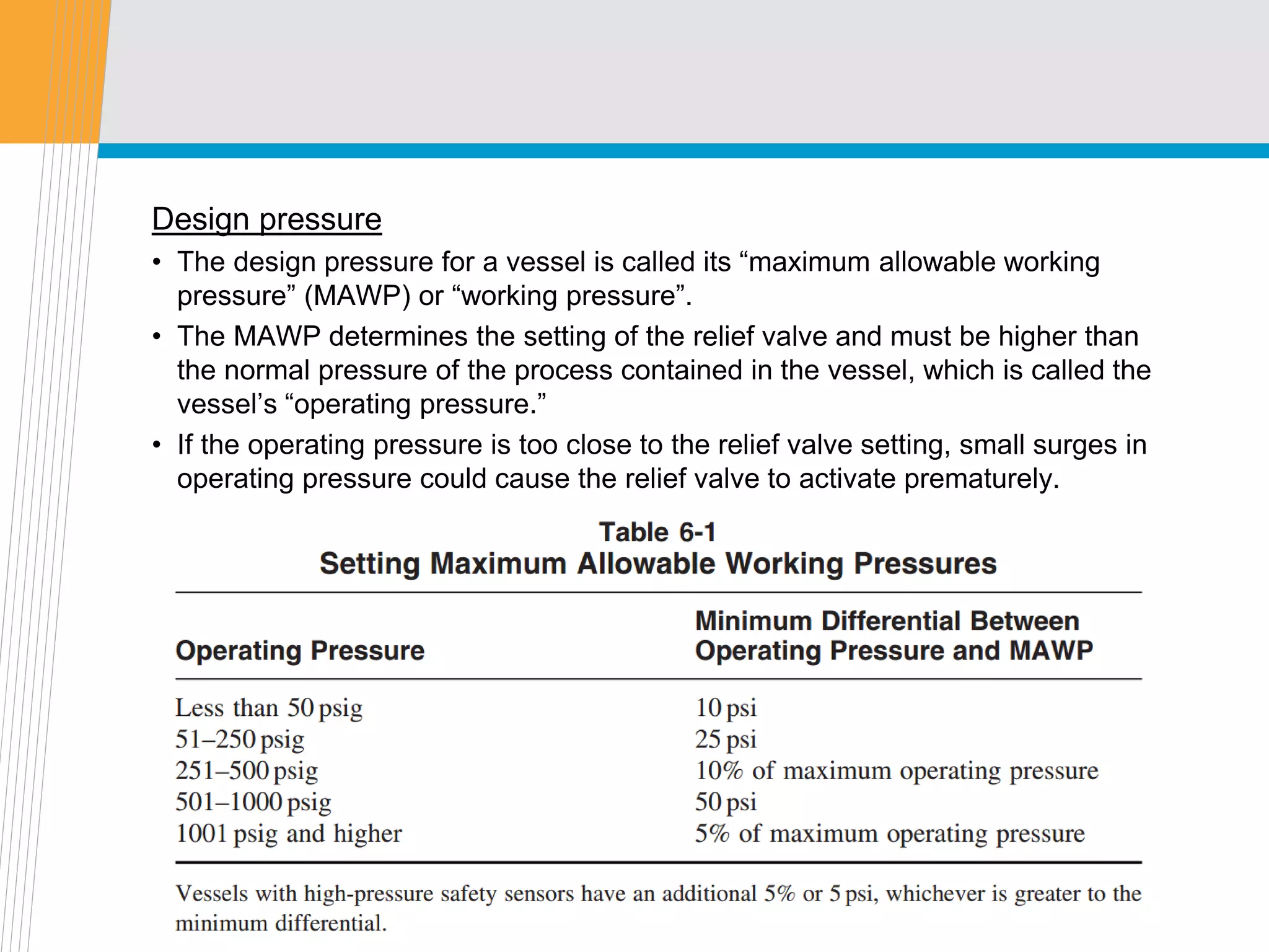
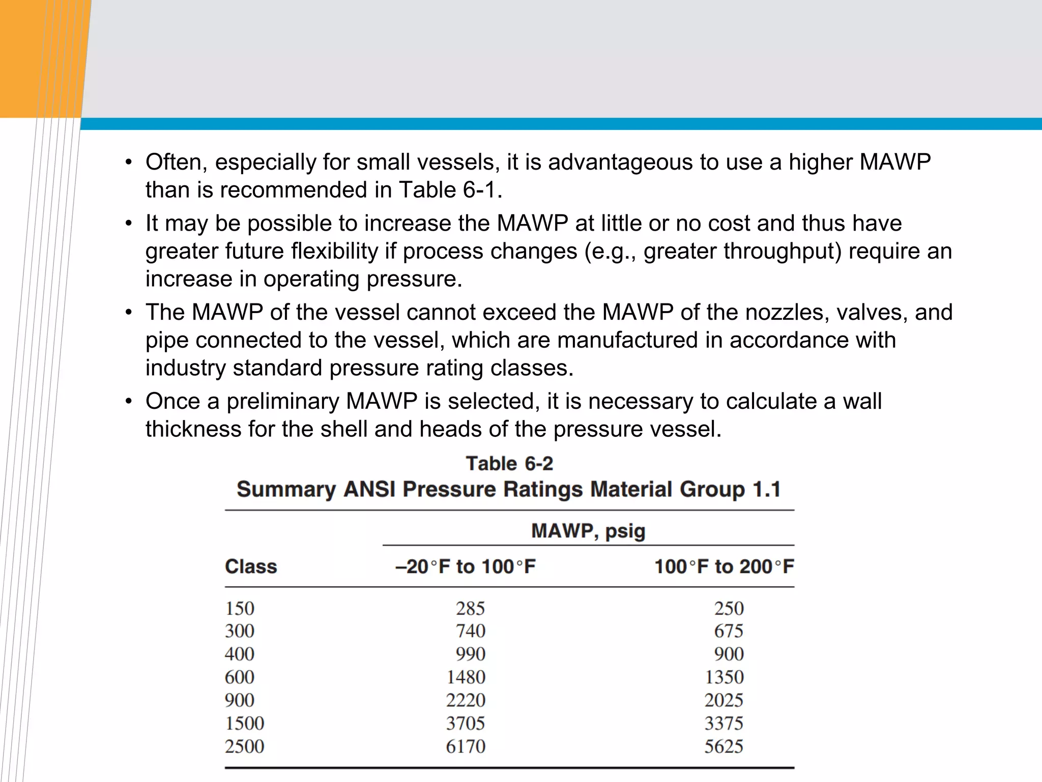
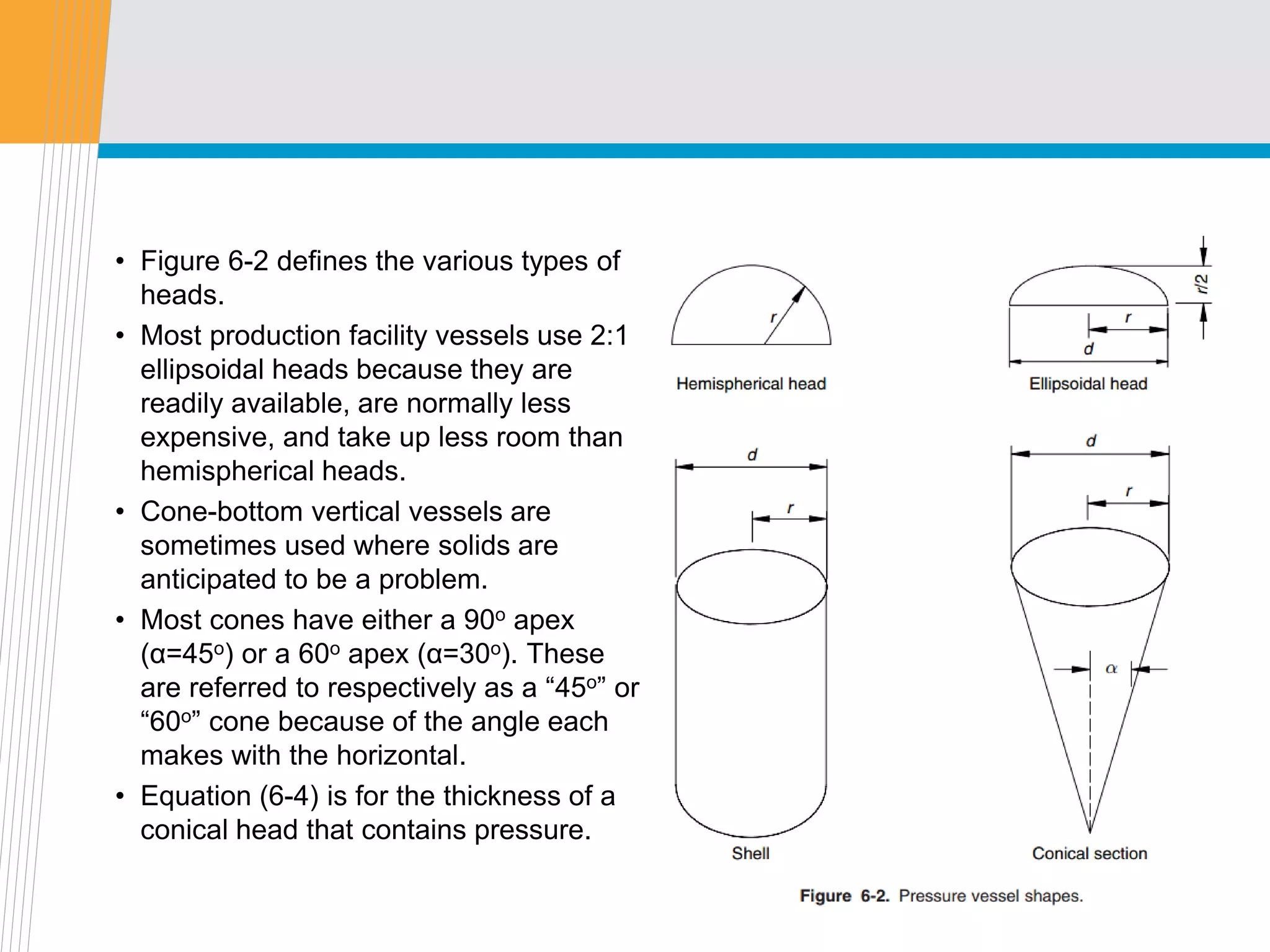
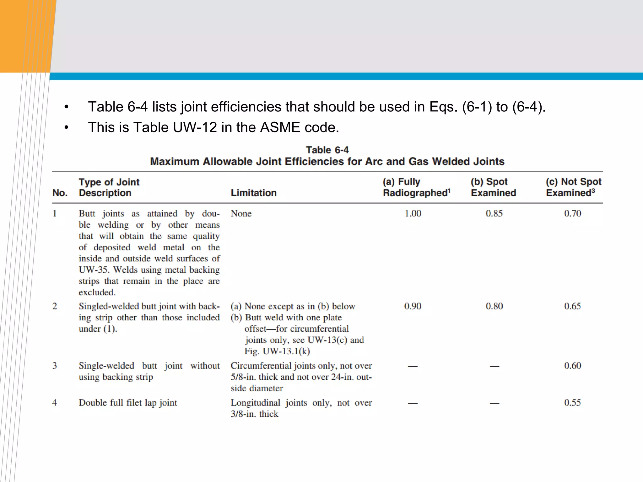
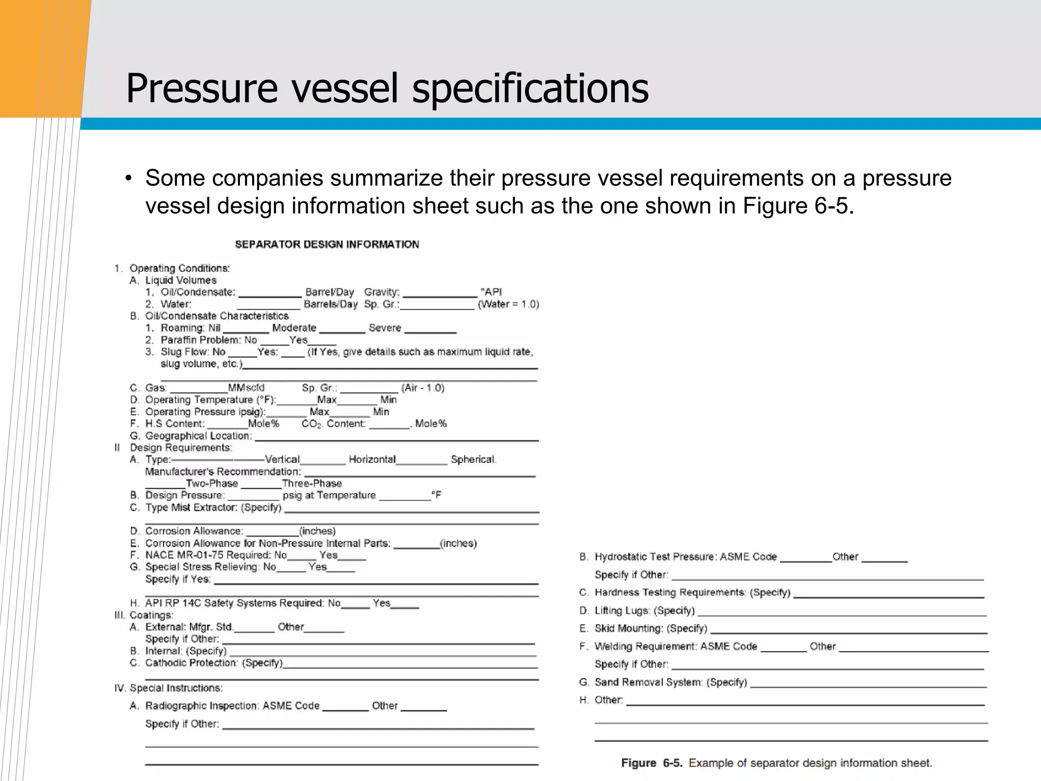
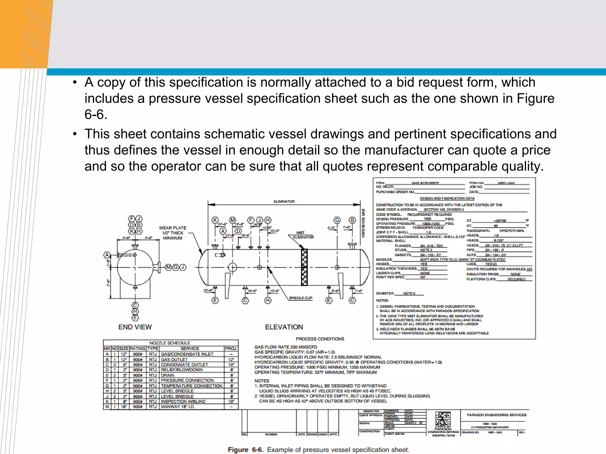
SlideShare a Scribd company logo
1 of 29
Download to read offline
Offshore Equipment
Yutaek Seo
Mechanical design of pressure vessel
Introduction
• Chapters 4 and 5 discuss the concepts for determining the diameter and length
of two-phase and three-phase vertical and horizontal separators.
• This chapter addresses the selection of design pressure rating and wall
thickness of pressure vessels.
• The purpose of this chapter is to present an overview of simple concepts of
mechanical design of pressure vessels that must be understood by a project
engineer specifying and purchasing this equipment.
• Most pressure vessels used in the oil and gas industry are designed and
inspected according to the American Society of Mechanical Engineers’ Boiler
and Pressure Vessel Code (ASME code).
• In particular, Section VIII of the code, “Pressure Vessels,” is particularly
important. Countries that do not use the ASME code have similar documents
and requirements.
• The use of non-code vessels should be discouraged to assure vessel
mechanical integrity.
Design considerations
Design temperature
• The maximum and minimum design temperatures for a vessel will determine
the maximum allowable stress value permitted for the material to be used in the
fabrication of the vessel.
• maximum temperature used in the design should not be less than the mean
metal temperature expected under the design operating conditions.
• The minimum temperature used in the design should be the lowest expected in
service except when lower temperatures are permitted by the rules of the
ASME code.
: lowest operating temperature, operational upset, auto-refrigeration, ambient
temperature, and any other source of cooling.
• The metal temperature should be determined by computation using accepted
heat transfer procedures or by measurement from equipment in service
Design pressure
• The design pressure for a vessel is called its “maximum allowable working
pressure” (MAWP) or “working pressure”.
• The MAWP determines the setting of the relief valve and must be higher than
the normal pressure of the process contained in the vessel, which is called the
vessel’s “operating pressure.”
• If the operating pressure is too close to the relief valve setting, small surges in
operating pressure could cause the relief valve to activate prematurely.
• Often, especially for small vessels, it is advantageous to use a higher MAWP
than is recommended in Table 6-1.
• It may be possible to increase the MAWP at little or no cost and thus have
greater future flexibility if process changes (e.g., greater throughput) require an
increase in operating pressure.
• The MAWP of the vessel cannot exceed the MAWP of the nozzles, valves, and
pipe connected to the vessel, which are manufactured in accordance with
industry standard pressure rating classes.
• Once a preliminary MAWP is selected, it is necessary to calculate a wall
thickness for the shell and heads of the pressure vessel.
Maximum allowable stress values
• The maximum allowable stress values to be used in the calculation of a vessel’s
wall thickness are given in the ASME code for many different materials.
• These stress values are a function of temperature. Section VIII of the ASME
code, which governs the design and construction of all pressure vessels with
operating pressures greater than 15 psig, is published in two divisions.
• Each sets its own maximum allowable stress values. Division 1, governing the
design by rules, is less stringent from the standpoint of certain design details
and inspection procedures, and thus incorporates a higher safety factor.
: The 1998 edition incorporates a safety factor of 4
: The 2001 and later editions incorporate a safety factor of 3.5.
: The 2001 edition of the code yields higher allowable stresses and thus smaller wall
thicknesses.
: For example, using a material with a 60,000-psi tensile strength, a vessel built under the
1998 edition (safety factor = 4) yields a maximum allowable stress value of 15,000 psi
while a vessel built under the 2001 edition (safety factor = 3.5) yields a maximum
allowable stress value of 17,142 psi.
• On the other hand, Division 2 governs the design by analysis and incorporates
a lower safety factor of 3.
: Thus, the maximum allowable stress value for a 60,000-psi tensile strength material will
become 20,000 psi.
• Many companies require that all their pressure vessels be constructed in
accordance with Division 2 because of the more exacting standards.
• Others find that they can purchase less expensive vessels by allowing
manufacturers the choice of either Division 1 or Division 2. Normally,
manufacturers will choose Division 1 for low-pressure vessels and Division 2 for
high-pressure vessels.
• The maximum allowable stress values at normal temperature range for the
steel plates most commonly used in the fabrication of pressure vessels are
given in Table 6-3.
• For stress values at higher temperatures and for other materials, the latest
edition of the ASME code should be referenced.
Determining wall thickness
• ASME code section VIII, Division 1
where
S = maximum allowable stress value, psi (kPa),
t = thickness, excluding corrosion allowance, in. (mm),
P = maximum allowable working pressure, psig (kPa),
r = inside radius before corrosion allowance is added, in. (mm),
d = inside diameter before corrosion allowance is added, in. (mm),
E = joint efficiency, see Table 6-4 (most vessels are fabricated in accordance with type of joint no. 1),
α = half the angle of the apex of the cone.
• Figure 6-1 summarizes the formulas for pressure vessels under internal
pressure (ASME Section VIII, Division 1).
• Figure 6-2 defines the various types of
heads.
• Most production facility vessels use 2:1
ellipsoidal heads because they are
readily available, are normally less
expensive, and take up less room than
hemispherical heads.
• Cone-bottom vertical vessels are
sometimes used where solids are
anticipated to be a problem.
• Most cones have either a 90o apex
(α=45o) or a 60o apex (α=30o). These
are referred to respectively as a “45o” or
“60o” cone because of the angle each
makes with the horizontal.
• Equation (6-4) is for the thickness of a
conical head that contains pressure.
• Some operators use internal cones within vertical vessels with standard
ellipsoidal heads as shown in Figure 6-3. The ellipsoidal heads contain the
pressure, and thus the internal cone can be made of very thin steel.
• Table 6-4 lists joint efficiencies that should be used in Eqs. (6-1) to (6-4).
• This is Table UW-12 in the ASME code.
• Table 6-5 lists some of the common material types used to construct pressure
vessels.
• Individual operating companies have their own standards, which differ from
those listed in this table.
Corrosion allowance
• Typically, a corrosion allowance of 0.125 in. for non-corrosive service and 0.250 in. for
corrosive service is added to the wall thickness calculated in Eqs. (6-1) to (6-4).
Inspection Procedures
• All ASME code vessels are inspected by an approved code inspector.
• The manufacturer will supply code papers signed by the inspector. The
nameplate on the vessel will be stamped to signify it has met the requirements
of the code.
• One of these requirements is that the vessel was pressure tested (1998 edition,
1.5 times the MAWP; 2001 and later editions, 1.3 times the MAWP). However,
this is only one of the requirements.
• The mere fact that a vessel is pressure tested 1.3 or 1.5 times the MAWP does
not signify that it has met all the design and quality assurance safety aspects of
the code.
• It must be pointed out that a code stamp does not necessarily mean that the
vessel is fabricated in accordance with critical nozzle dimensions or internal
devices as required by the process. The code inspector is only interested in
those aspects that relate to the pressure handling integrity of the vessel.
• The owner must do his own inspection to assure that nozzle locations are within
tolerance, vessel internals are installed as designed, coatings are applied
properly, etc.
Estimating vessel weights
• It is important to be able to estimate vessel weights, since most cost estimating
procedures start with the weight of the vessel.
• The vessel weight, both empty and full with water, may be necessary to
adequately design a foundation or to assure that the vessel can be lifted or
erected once it gets to the construction site.
• The weight of a vessel is made up of the weight of the shell, the weight of the
heads, and the weight of internals, nozzles, pedestals, and skirts.
• Shell weight can be estimated from
• The weight of one 2:1 ellipsoidal head is approximately
• The weight of nozzles and internals can be estimated at 5 to 10% of the sum of
the shell and head weights.
• As a first approximation, the weight of a skirt can be estimated as the same
thickness as the shell (neglecting the corrosion allowance) with a length given
by Eq. (6.8) for an ellipsoidal head and Eq. (6.9) for a conical head.
• For very tall vessels the skirt will have to be checked to assure it is sufficient to
support both the weight of the vessel and its appentorances and the overturning
moment generated by wind forces.
• The weight of pedestals for a horizontal vessel can be estimated as 10% of the
total weight of the vessel.
Pressure vessel specifications
• Some companies summarize their pressure vessel requirements on a pressure
vessel design information sheet such as the one shown in Figure 6-5.
• Some companies have a detailed general specification for the construction of
pressure vessels, which defines the overall quality of fabrication required and
addresses specific items such as
• Code compliance
• Design conditions and materials
• Design details
Vessel design and tolerances
Vessel connections (nozzle schedules)
Vessel internals
Ladders, cages, platforms, and stairs
Vessel supports and lifting lugs
Insulation supports
Shop drawings
• Fabrication
General
Welding
Painting
Inspection and testing
Identification stamping
Drawings, final reports, and data sheets
Preparation for shipment
• A copy of this specification is normally attached to a bid request form, which
includes a pressure vessel specification sheet such as the one shown in Figure
6-6.
• This sheet contains schematic vessel drawings and pertinent specifications and
thus defines the vessel in enough detail so the manufacturer can quote a price
and so the operator can be sure that all quotes represent comparable quality.
Shop drawings
• Before the vessel fabrication can proceed, the fabricator will develop complete
drawings and have these drawings approved by the representative of the
engineering firm and/or the operating company.
• These drawings are called shop drawings.
Nozzles
• Nozzles should be sized according to pipe sizing criteria, such as those
provided in API RP 14E.
• The outlet nozzle is generally the same size as the inlet nozzle.
• To prevent baffle destruction due to impingement, the entering fluid velocity is
to be limited as
Vortex Breaker
• As liquid flows out of the exit nozzle, it will swirl and create a vortex.
• Vortexing would carry the gas out with the liquid. Therefore, all liquid outlet
nozzles should be equipped with a vortex breaker.
• Figure 6-11 shows several vortex breaker designs. Additional designs can be
found in the Pressure Vessel Handbook. Most designs depend on baffles
around or above the outlet to prevent swirling.
• Manways
: large openings that allow personnel access to the vessel internals for their maintenance
and/or replacement.
• Vessel supports
: Small vertical vessels may be supported by angle support legs, while larger vertical
vessels are generally supported by a skirt support.
• Ladder and platform
: A ladder and platform should be provided if operators are required to climb up to the top
of the vessel regularly.
• Pressure relief devices
: All pressure vessels should be equipped with one or more pressure safety valves
(PSVs) to prevent overpressure. (requirement of both the ASME code and API RP 14C)
: The PSV should be located upstream of the mist extractor
• Corrosion protection
: Common corrosion protection methods include internal coatings with synthetic
polymeric materials and galvanic (sacrificial) anodes.
: All pressure vessels that handle corrosive fluids should be monitored periodically.
Ultrasonic surveys can locate discontinuities in the metal structure, which will indicate
corrosion damages.
Thank you, Question?
?

More Related Content

What's hot

38785106 api-tank-design
38785106 api-tank-design38785106 api-tank-design
38785106 api-tank-design141jdf
 
ASME BOILER & PRESSURE SECTION VIII.ppt
ASME BOILER & PRESSURE SECTION VIII.pptASME BOILER & PRESSURE SECTION VIII.ppt
ASME BOILER & PRESSURE SECTION VIII.ppthesham ismail
 
Pressure Relief valve sizing and design
Pressure Relief valve sizing and designPressure Relief valve sizing and design
Pressure Relief valve sizing and designHéctor Nguema Ondo
 
Tank design - powerpoint slides
Tank design - powerpoint slidesTank design - powerpoint slides
Tank design - powerpoint slidesmoamen mohamed
 
Pressure Reliveing Devices1
Pressure Reliveing Devices1Pressure Reliveing Devices1
Pressure Reliveing Devices1Om Pratap Singh
 
Heat exchanger: Shell And Tube Heat Exchanger
Heat exchanger: Shell And Tube Heat ExchangerHeat exchanger: Shell And Tube Heat Exchanger
Heat exchanger: Shell And Tube Heat ExchangerAkshay Sarita
 
ASME Section VIII Div 1. design training
ASME Section VIII Div 1.  design trainingASME Section VIII Div 1.  design training
ASME Section VIII Div 1. design trainingSam Jose
 
Skirt support for vertical vessal 16 06,07,08,09
Skirt support for vertical vessal 16 06,07,08,09Skirt support for vertical vessal 16 06,07,08,09
Skirt support for vertical vessal 16 06,07,08,09Shahrukh Vahora
 
ASME Section viii Div-1 Traing ppt..pdf
ASME Section viii Div-1  Traing ppt..pdfASME Section viii Div-1  Traing ppt..pdf
ASME Section viii Div-1 Traing ppt..pdfBaber6
 
fundamentals of Piping engineering
fundamentals of Piping engineeringfundamentals of Piping engineering
fundamentals of Piping engineeringMobinVarghese8
 
Pressure relief system_design
Pressure relief system_designPressure relief system_design
Pressure relief system_designRahul Tewari
 

What's hot (20)

38785106 api-tank-design
38785106 api-tank-design38785106 api-tank-design
38785106 api-tank-design
 
Ced_ppt
Ced_pptCed_ppt
Ced_ppt
 
ASME BOILER & PRESSURE SECTION VIII.ppt
ASME BOILER & PRESSURE SECTION VIII.pptASME BOILER & PRESSURE SECTION VIII.ppt
ASME BOILER & PRESSURE SECTION VIII.ppt
 
Pressure Relief valve sizing and design
Pressure Relief valve sizing and designPressure Relief valve sizing and design
Pressure Relief valve sizing and design
 
Tank design - powerpoint slides
Tank design - powerpoint slidesTank design - powerpoint slides
Tank design - powerpoint slides
 
Tank design - word
Tank design - wordTank design - word
Tank design - word
 
design and analysis of pressure vessel
design and analysis of pressure vesseldesign and analysis of pressure vessel
design and analysis of pressure vessel
 
Pressure Reliveing Devices1
Pressure Reliveing Devices1Pressure Reliveing Devices1
Pressure Reliveing Devices1
 
2011 02-22-nfpa-30-tank-storage-workbook
2011 02-22-nfpa-30-tank-storage-workbook2011 02-22-nfpa-30-tank-storage-workbook
2011 02-22-nfpa-30-tank-storage-workbook
 
Pipe line sizing
Pipe line sizingPipe line sizing
Pipe line sizing
 
Heat exchanger: Shell And Tube Heat Exchanger
Heat exchanger: Shell And Tube Heat ExchangerHeat exchanger: Shell And Tube Heat Exchanger
Heat exchanger: Shell And Tube Heat Exchanger
 
Design of pressure vessel
Design of pressure vesselDesign of pressure vessel
Design of pressure vessel
 
Asme b31,pressure piping code
Asme b31,pressure piping codeAsme b31,pressure piping code
Asme b31,pressure piping code
 
ASME Section VIII Div 1. design training
ASME Section VIII Div 1.  design trainingASME Section VIII Div 1.  design training
ASME Section VIII Div 1. design training
 
Skirt support for vertical vessal 16 06,07,08,09
Skirt support for vertical vessal 16 06,07,08,09Skirt support for vertical vessal 16 06,07,08,09
Skirt support for vertical vessal 16 06,07,08,09
 
Process Plant design fundementals
Process Plant design fundementalsProcess Plant design fundementals
Process Plant design fundementals
 
ASME Section viii Div-1 Traing ppt..pdf
ASME Section viii Div-1  Traing ppt..pdfASME Section viii Div-1  Traing ppt..pdf
ASME Section viii Div-1 Traing ppt..pdf
 
fundamentals of Piping engineering
fundamentals of Piping engineeringfundamentals of Piping engineering
fundamentals of Piping engineering
 
Pressure relief system_design
Pressure relief system_designPressure relief system_design
Pressure relief system_design
 
Hysys simulation
Hysys simulationHysys simulation
Hysys simulation
 

Similar to 4. Mechanical design of pressure vessels_slides.pdf

office final ppt [7760835] final update
office final ppt [7760835] final updateoffice final ppt [7760835] final update
office final ppt [7760835] final updateAashish Soin
 
pressure vessel details for design and it components
pressure vessel details for design and it componentspressure vessel details for design and it components
pressure vessel details for design and it componentsdhaneshmech1
 
CH3080_pressure_vessels.ppt
CH3080_pressure_vessels.pptCH3080_pressure_vessels.ppt
CH3080_pressure_vessels.pptYahiya Ahmed
 
Aboveground_storage_tank_design_and_operation.pdf
Aboveground_storage_tank_design_and_operation.pdfAboveground_storage_tank_design_and_operation.pdf
Aboveground_storage_tank_design_and_operation.pdfFerranCabre
 
Asme Code Calculations Cylindrical Components
Asme Code Calculations  Cylindrical ComponentsAsme Code Calculations  Cylindrical Components
Asme Code Calculations Cylindrical ComponentsAbdulbari Hajamohaideen
 
Cswip 11-01 - plant inspection- Week 2 cours
Cswip 11-01 - plant inspection- Week 2 coursCswip 11-01 - plant inspection- Week 2 cours
Cswip 11-01 - plant inspection- Week 2 coursRafik Guerbous
 
Chemical Engineering Apparatus Design lecture note
Chemical Engineering Apparatus Design lecture noteChemical Engineering Apparatus Design lecture note
Chemical Engineering Apparatus Design lecture noteMuktarAbdu3
 
Chemical Engineering Apparatus Design Lecture note.pdf
Chemical Engineering  Apparatus Design Lecture note.pdfChemical Engineering  Apparatus Design Lecture note.pdf
Chemical Engineering Apparatus Design Lecture note.pdfMuktarAbdu2
 
Chemical Engineering Apparatus Design lecture note
Chemical Engineering Apparatus Design lecture noteChemical Engineering Apparatus Design lecture note
Chemical Engineering Apparatus Design lecture noteMuktar Abdu
 
Stress analysis of storage tank piping - Jeba Anand
Stress analysis of storage tank  piping - Jeba AnandStress analysis of storage tank  piping - Jeba Anand
Stress analysis of storage tank piping - Jeba AnandJeba Anand Nadar
 
Design & Stress Analysis of a Cylinder with Closed ends using ANSYS
Design & Stress Analysis of a Cylinder with Closed ends using ANSYSDesign & Stress Analysis of a Cylinder with Closed ends using ANSYS
Design & Stress Analysis of a Cylinder with Closed ends using ANSYSIJERA Editor
 
Fabrication of storage buffer vessel
Fabrication of storage buffer vesselFabrication of storage buffer vessel
Fabrication of storage buffer vesselNishant Rao Boddeda
 
500630977-CH-1-Pressure-Vessel-Design-1.pdf
500630977-CH-1-Pressure-Vessel-Design-1.pdf500630977-CH-1-Pressure-Vessel-Design-1.pdf
500630977-CH-1-Pressure-Vessel-Design-1.pdfAnuragKumarSinghSing
 
Thermal Stress Analysis of Casing in Cyclic Steam Injected Well
Thermal Stress Analysis of Casing in Cyclic Steam Injected WellThermal Stress Analysis of Casing in Cyclic Steam Injected Well
Thermal Stress Analysis of Casing in Cyclic Steam Injected WellIRJET Journal
 

Similar to 4. Mechanical design of pressure vessels_slides.pdf (20)

office final ppt [7760835] final update
office final ppt [7760835] final updateoffice final ppt [7760835] final update
office final ppt [7760835] final update
 
pv_rules.pdf
pv_rules.pdfpv_rules.pdf
pv_rules.pdf
 
pv_rules.pdf
pv_rules.pdfpv_rules.pdf
pv_rules.pdf
 
pressure vessel details for design and it components
pressure vessel details for design and it componentspressure vessel details for design and it components
pressure vessel details for design and it components
 
CH3080_pressure_vessels.ppt
CH3080_pressure_vessels.pptCH3080_pressure_vessels.ppt
CH3080_pressure_vessels.ppt
 
Aboveground_storage_tank_design_and_operation.pdf
Aboveground_storage_tank_design_and_operation.pdfAboveground_storage_tank_design_and_operation.pdf
Aboveground_storage_tank_design_and_operation.pdf
 
Descon Presentation
Descon PresentationDescon Presentation
Descon Presentation
 
Asme Code Calculations Cylindrical Components
Asme Code Calculations  Cylindrical ComponentsAsme Code Calculations  Cylindrical Components
Asme Code Calculations Cylindrical Components
 
Cswip 11-01 - plant inspection- Week 2 cours
Cswip 11-01 - plant inspection- Week 2 coursCswip 11-01 - plant inspection- Week 2 cours
Cswip 11-01 - plant inspection- Week 2 cours
 
10572621.ppt
10572621.ppt10572621.ppt
10572621.ppt
 
10572621.ppt
10572621.ppt10572621.ppt
10572621.ppt
 
Chemical Engineering Apparatus Design lecture note
Chemical Engineering Apparatus Design lecture noteChemical Engineering Apparatus Design lecture note
Chemical Engineering Apparatus Design lecture note
 
Chemical Engineering Apparatus Design Lecture note.pdf
Chemical Engineering  Apparatus Design Lecture note.pdfChemical Engineering  Apparatus Design Lecture note.pdf
Chemical Engineering Apparatus Design Lecture note.pdf
 
Chemical Engineering Apparatus Design lecture note
Chemical Engineering Apparatus Design lecture noteChemical Engineering Apparatus Design lecture note
Chemical Engineering Apparatus Design lecture note
 
Stress analysis of storage tank piping - Jeba Anand
Stress analysis of storage tank  piping - Jeba AnandStress analysis of storage tank  piping - Jeba Anand
Stress analysis of storage tank piping - Jeba Anand
 
Design & Stress Analysis of a Cylinder with Closed ends using ANSYS
Design & Stress Analysis of a Cylinder with Closed ends using ANSYSDesign & Stress Analysis of a Cylinder with Closed ends using ANSYS
Design & Stress Analysis of a Cylinder with Closed ends using ANSYS
 
Fabrication of storage buffer vessel
Fabrication of storage buffer vesselFabrication of storage buffer vessel
Fabrication of storage buffer vessel
 
500630977-CH-1-Pressure-Vessel-Design-1.pdf
500630977-CH-1-Pressure-Vessel-Design-1.pdf500630977-CH-1-Pressure-Vessel-Design-1.pdf
500630977-CH-1-Pressure-Vessel-Design-1.pdf
 
Thermal Stress Analysis of Casing in Cyclic Steam Injected Well
Thermal Stress Analysis of Casing in Cyclic Steam Injected WellThermal Stress Analysis of Casing in Cyclic Steam Injected Well
Thermal Stress Analysis of Casing in Cyclic Steam Injected Well
 
Casing_Design(1).ppt
Casing_Design(1).pptCasing_Design(1).ppt
Casing_Design(1).ppt
 

Recently uploaded

办理学位证(NTU证书)新加坡南洋理工大学毕业证成绩单原版一比一
办理学位证(NTU证书)新加坡南洋理工大学毕业证成绩单原版一比一办理学位证(NTU证书)新加坡南洋理工大学毕业证成绩单原版一比一
办理学位证(NTU证书)新加坡南洋理工大学毕业证成绩单原版一比一A SSS
 
PORTAFOLIO 2024_ ANASTASIYA KUDINOVA
PORTAFOLIO   2024_  ANASTASIYA  KUDINOVAPORTAFOLIO   2024_  ANASTASIYA  KUDINOVA
PORTAFOLIO 2024_ ANASTASIYA KUDINOVAAnastasiya Kudinova
 
VIP Call Girl Amravati Aashi 8250192130 Independent Escort Service Amravati
VIP Call Girl Amravati Aashi 8250192130 Independent Escort Service AmravatiVIP Call Girl Amravati Aashi 8250192130 Independent Escort Service Amravati
VIP Call Girl Amravati Aashi 8250192130 Independent Escort Service AmravatiSuhani Kapoor
 
VIP Call Girls Service Kukatpally Hyderabad Call +91-8250192130
VIP Call Girls Service Kukatpally Hyderabad Call +91-8250192130VIP Call Girls Service Kukatpally Hyderabad Call +91-8250192130
VIP Call Girls Service Kukatpally Hyderabad Call +91-8250192130Suhani Kapoor
 
Call Girls In Safdarjung Enclave 24/7✡️9711147426✡️ Escorts Service
Call Girls In Safdarjung Enclave 24/7✡️9711147426✡️ Escorts ServiceCall Girls In Safdarjung Enclave 24/7✡️9711147426✡️ Escorts Service
Call Girls In Safdarjung Enclave 24/7✡️9711147426✡️ Escorts Servicejennyeacort
 
VIP Call Girls Service Mehdipatnam Hyderabad Call +91-8250192130
VIP Call Girls Service Mehdipatnam Hyderabad Call +91-8250192130VIP Call Girls Service Mehdipatnam Hyderabad Call +91-8250192130
VIP Call Girls Service Mehdipatnam Hyderabad Call +91-8250192130Suhani Kapoor
 
Call Girls Meghani Nagar 7397865700 Independent Call Girls
Call Girls Meghani Nagar 7397865700  Independent Call GirlsCall Girls Meghani Nagar 7397865700  Independent Call Girls
Call Girls Meghani Nagar 7397865700 Independent Call Girlsssuser7cb4ff
 
Untitled presedddddddddddddddddntation (1).pptx
Untitled presedddddddddddddddddntation (1).pptxUntitled presedddddddddddddddddntation (1).pptx
Untitled presedddddddddddddddddntation (1).pptxmapanig881
 
Call Girls Aslali 7397865700 Ridhima Hire Me Full Night
Call Girls Aslali 7397865700 Ridhima Hire Me Full NightCall Girls Aslali 7397865700 Ridhima Hire Me Full Night
Call Girls Aslali 7397865700 Ridhima Hire Me Full Nightssuser7cb4ff
 
3D Printing And Designing Final Report.pdf
3D Printing And Designing Final Report.pdf3D Printing And Designing Final Report.pdf
3D Printing And Designing Final Report.pdfSwaraliBorhade
 
办理学位证(SFU证书)西蒙菲莎大学毕业证成绩单原版一比一
办理学位证(SFU证书)西蒙菲莎大学毕业证成绩单原版一比一办理学位证(SFU证书)西蒙菲莎大学毕业证成绩单原版一比一
办理学位证(SFU证书)西蒙菲莎大学毕业证成绩单原版一比一F dds
 
Call Girls in Ashok Nagar Delhi ✡️9711147426✡️ Escorts Service
Call Girls in Ashok Nagar Delhi ✡️9711147426✡️ Escorts ServiceCall Girls in Ashok Nagar Delhi ✡️9711147426✡️ Escorts Service
Call Girls in Ashok Nagar Delhi ✡️9711147426✡️ Escorts Servicejennyeacort
 
Abu Dhabi Call Girls O58993O4O2 Call Girls in Abu Dhabi`
Abu Dhabi Call Girls O58993O4O2 Call Girls in Abu Dhabi`Abu Dhabi Call Girls O58993O4O2 Call Girls in Abu Dhabi`
Abu Dhabi Call Girls O58993O4O2 Call Girls in Abu Dhabi`dajasot375
 
ARt app | UX Case Study
ARt app | UX Case StudyARt app | UX Case Study
ARt app | UX Case StudySophia Viganò
 
How to Be Famous in your Field just visit our Site
How to Be Famous in your Field just visit our SiteHow to Be Famous in your Field just visit our Site
How to Be Famous in your Field just visit our Sitegalleryaagency
 
Call In girls Bhikaji Cama Place 🔝 ⇛8377877756 FULL Enjoy Delhi NCR
Call In girls Bhikaji Cama Place 🔝 ⇛8377877756 FULL Enjoy Delhi NCRCall In girls Bhikaji Cama Place 🔝 ⇛8377877756 FULL Enjoy Delhi NCR
Call In girls Bhikaji Cama Place 🔝 ⇛8377877756 FULL Enjoy Delhi NCRdollysharma2066
 
办理(UC毕业证书)查尔斯顿大学毕业证成绩单原版一比一
办理(UC毕业证书)查尔斯顿大学毕业证成绩单原版一比一办理(UC毕业证书)查尔斯顿大学毕业证成绩单原版一比一
办理(UC毕业证书)查尔斯顿大学毕业证成绩单原版一比一z xss
 
Passbook project document_april_21__.pdf
Passbook project document_april_21__.pdfPassbook project document_april_21__.pdf
Passbook project document_april_21__.pdfvaibhavkanaujia
 
NATA 2024 SYLLABUS, full syllabus explained in detail
NATA 2024 SYLLABUS, full syllabus explained in detailNATA 2024 SYLLABUS, full syllabus explained in detail
NATA 2024 SYLLABUS, full syllabus explained in detailDesigntroIntroducing
 

Recently uploaded (20)

办理学位证(NTU证书)新加坡南洋理工大学毕业证成绩单原版一比一
办理学位证(NTU证书)新加坡南洋理工大学毕业证成绩单原版一比一办理学位证(NTU证书)新加坡南洋理工大学毕业证成绩单原版一比一
办理学位证(NTU证书)新加坡南洋理工大学毕业证成绩单原版一比一
 
PORTAFOLIO 2024_ ANASTASIYA KUDINOVA
PORTAFOLIO   2024_  ANASTASIYA  KUDINOVAPORTAFOLIO   2024_  ANASTASIYA  KUDINOVA
PORTAFOLIO 2024_ ANASTASIYA KUDINOVA
 
VIP Call Girl Amravati Aashi 8250192130 Independent Escort Service Amravati
VIP Call Girl Amravati Aashi 8250192130 Independent Escort Service AmravatiVIP Call Girl Amravati Aashi 8250192130 Independent Escort Service Amravati
VIP Call Girl Amravati Aashi 8250192130 Independent Escort Service Amravati
 
VIP Call Girls Service Kukatpally Hyderabad Call +91-8250192130
VIP Call Girls Service Kukatpally Hyderabad Call +91-8250192130VIP Call Girls Service Kukatpally Hyderabad Call +91-8250192130
VIP Call Girls Service Kukatpally Hyderabad Call +91-8250192130
 
Call Girls In Safdarjung Enclave 24/7✡️9711147426✡️ Escorts Service
Call Girls In Safdarjung Enclave 24/7✡️9711147426✡️ Escorts ServiceCall Girls In Safdarjung Enclave 24/7✡️9711147426✡️ Escorts Service
Call Girls In Safdarjung Enclave 24/7✡️9711147426✡️ Escorts Service
 
VIP Call Girls Service Mehdipatnam Hyderabad Call +91-8250192130
VIP Call Girls Service Mehdipatnam Hyderabad Call +91-8250192130VIP Call Girls Service Mehdipatnam Hyderabad Call +91-8250192130
VIP Call Girls Service Mehdipatnam Hyderabad Call +91-8250192130
 
Call Girls Meghani Nagar 7397865700 Independent Call Girls
Call Girls Meghani Nagar 7397865700  Independent Call GirlsCall Girls Meghani Nagar 7397865700  Independent Call Girls
Call Girls Meghani Nagar 7397865700 Independent Call Girls
 
Untitled presedddddddddddddddddntation (1).pptx
Untitled presedddddddddddddddddntation (1).pptxUntitled presedddddddddddddddddntation (1).pptx
Untitled presedddddddddddddddddntation (1).pptx
 
Call Girls Aslali 7397865700 Ridhima Hire Me Full Night
Call Girls Aslali 7397865700 Ridhima Hire Me Full NightCall Girls Aslali 7397865700 Ridhima Hire Me Full Night
Call Girls Aslali 7397865700 Ridhima Hire Me Full Night
 
3D Printing And Designing Final Report.pdf
3D Printing And Designing Final Report.pdf3D Printing And Designing Final Report.pdf
3D Printing And Designing Final Report.pdf
 
办理学位证(SFU证书)西蒙菲莎大学毕业证成绩单原版一比一
办理学位证(SFU证书)西蒙菲莎大学毕业证成绩单原版一比一办理学位证(SFU证书)西蒙菲莎大学毕业证成绩单原版一比一
办理学位证(SFU证书)西蒙菲莎大学毕业证成绩单原版一比一
 
Call Girls in Ashok Nagar Delhi ✡️9711147426✡️ Escorts Service
Call Girls in Ashok Nagar Delhi ✡️9711147426✡️ Escorts ServiceCall Girls in Ashok Nagar Delhi ✡️9711147426✡️ Escorts Service
Call Girls in Ashok Nagar Delhi ✡️9711147426✡️ Escorts Service
 
Abu Dhabi Call Girls O58993O4O2 Call Girls in Abu Dhabi`
Abu Dhabi Call Girls O58993O4O2 Call Girls in Abu Dhabi`Abu Dhabi Call Girls O58993O4O2 Call Girls in Abu Dhabi`
Abu Dhabi Call Girls O58993O4O2 Call Girls in Abu Dhabi`
 
ARt app | UX Case Study
ARt app | UX Case StudyARt app | UX Case Study
ARt app | UX Case Study
 
How to Be Famous in your Field just visit our Site
How to Be Famous in your Field just visit our SiteHow to Be Famous in your Field just visit our Site
How to Be Famous in your Field just visit our Site
 
Call In girls Bhikaji Cama Place 🔝 ⇛8377877756 FULL Enjoy Delhi NCR
Call In girls Bhikaji Cama Place 🔝 ⇛8377877756 FULL Enjoy Delhi NCRCall In girls Bhikaji Cama Place 🔝 ⇛8377877756 FULL Enjoy Delhi NCR
Call In girls Bhikaji Cama Place 🔝 ⇛8377877756 FULL Enjoy Delhi NCR
 
办理(UC毕业证书)查尔斯顿大学毕业证成绩单原版一比一
办理(UC毕业证书)查尔斯顿大学毕业证成绩单原版一比一办理(UC毕业证书)查尔斯顿大学毕业证成绩单原版一比一
办理(UC毕业证书)查尔斯顿大学毕业证成绩单原版一比一
 
Passbook project document_april_21__.pdf
Passbook project document_april_21__.pdfPassbook project document_april_21__.pdf
Passbook project document_april_21__.pdf
 
NATA 2024 SYLLABUS, full syllabus explained in detail
NATA 2024 SYLLABUS, full syllabus explained in detailNATA 2024 SYLLABUS, full syllabus explained in detail
NATA 2024 SYLLABUS, full syllabus explained in detail
 
Cheap Rate ➥8448380779 ▻Call Girls In Iffco Chowk Gurgaon
Cheap Rate ➥8448380779 ▻Call Girls In Iffco Chowk GurgaonCheap Rate ➥8448380779 ▻Call Girls In Iffco Chowk Gurgaon
Cheap Rate ➥8448380779 ▻Call Girls In Iffco Chowk Gurgaon
 

4. Mechanical design of pressure vessels_slides.pdf

  • 2. Mechanical design of pressure vessel Introduction • Chapters 4 and 5 discuss the concepts for determining the diameter and length of two-phase and three-phase vertical and horizontal separators. • This chapter addresses the selection of design pressure rating and wall thickness of pressure vessels. • The purpose of this chapter is to present an overview of simple concepts of mechanical design of pressure vessels that must be understood by a project engineer specifying and purchasing this equipment. • Most pressure vessels used in the oil and gas industry are designed and inspected according to the American Society of Mechanical Engineers’ Boiler and Pressure Vessel Code (ASME code). • In particular, Section VIII of the code, “Pressure Vessels,” is particularly important. Countries that do not use the ASME code have similar documents and requirements. • The use of non-code vessels should be discouraged to assure vessel mechanical integrity.
  • 3. Design considerations Design temperature • The maximum and minimum design temperatures for a vessel will determine the maximum allowable stress value permitted for the material to be used in the fabrication of the vessel. • maximum temperature used in the design should not be less than the mean metal temperature expected under the design operating conditions. • The minimum temperature used in the design should be the lowest expected in service except when lower temperatures are permitted by the rules of the ASME code. : lowest operating temperature, operational upset, auto-refrigeration, ambient temperature, and any other source of cooling. • The metal temperature should be determined by computation using accepted heat transfer procedures or by measurement from equipment in service
  • 4. Design pressure • The design pressure for a vessel is called its “maximum allowable working pressure” (MAWP) or “working pressure”. • The MAWP determines the setting of the relief valve and must be higher than the normal pressure of the process contained in the vessel, which is called the vessel’s “operating pressure.” • If the operating pressure is too close to the relief valve setting, small surges in operating pressure could cause the relief valve to activate prematurely.
  • 5. • Often, especially for small vessels, it is advantageous to use a higher MAWP than is recommended in Table 6-1. • It may be possible to increase the MAWP at little or no cost and thus have greater future flexibility if process changes (e.g., greater throughput) require an increase in operating pressure. • The MAWP of the vessel cannot exceed the MAWP of the nozzles, valves, and pipe connected to the vessel, which are manufactured in accordance with industry standard pressure rating classes. • Once a preliminary MAWP is selected, it is necessary to calculate a wall thickness for the shell and heads of the pressure vessel.
  • 6. Maximum allowable stress values • The maximum allowable stress values to be used in the calculation of a vessel’s wall thickness are given in the ASME code for many different materials. • These stress values are a function of temperature. Section VIII of the ASME code, which governs the design and construction of all pressure vessels with operating pressures greater than 15 psig, is published in two divisions. • Each sets its own maximum allowable stress values. Division 1, governing the design by rules, is less stringent from the standpoint of certain design details and inspection procedures, and thus incorporates a higher safety factor. : The 1998 edition incorporates a safety factor of 4 : The 2001 and later editions incorporate a safety factor of 3.5. : The 2001 edition of the code yields higher allowable stresses and thus smaller wall thicknesses. : For example, using a material with a 60,000-psi tensile strength, a vessel built under the 1998 edition (safety factor = 4) yields a maximum allowable stress value of 15,000 psi while a vessel built under the 2001 edition (safety factor = 3.5) yields a maximum allowable stress value of 17,142 psi. • On the other hand, Division 2 governs the design by analysis and incorporates a lower safety factor of 3. : Thus, the maximum allowable stress value for a 60,000-psi tensile strength material will become 20,000 psi.
  • 7. • Many companies require that all their pressure vessels be constructed in accordance with Division 2 because of the more exacting standards. • Others find that they can purchase less expensive vessels by allowing manufacturers the choice of either Division 1 or Division 2. Normally, manufacturers will choose Division 1 for low-pressure vessels and Division 2 for high-pressure vessels. • The maximum allowable stress values at normal temperature range for the steel plates most commonly used in the fabrication of pressure vessels are given in Table 6-3. • For stress values at higher temperatures and for other materials, the latest edition of the ASME code should be referenced.
  • 8.
  • 9. Determining wall thickness • ASME code section VIII, Division 1 where S = maximum allowable stress value, psi (kPa), t = thickness, excluding corrosion allowance, in. (mm), P = maximum allowable working pressure, psig (kPa), r = inside radius before corrosion allowance is added, in. (mm), d = inside diameter before corrosion allowance is added, in. (mm), E = joint efficiency, see Table 6-4 (most vessels are fabricated in accordance with type of joint no. 1), α = half the angle of the apex of the cone.
  • 10. • Figure 6-1 summarizes the formulas for pressure vessels under internal pressure (ASME Section VIII, Division 1).
  • 11. • Figure 6-2 defines the various types of heads. • Most production facility vessels use 2:1 ellipsoidal heads because they are readily available, are normally less expensive, and take up less room than hemispherical heads. • Cone-bottom vertical vessels are sometimes used where solids are anticipated to be a problem. • Most cones have either a 90o apex (α=45o) or a 60o apex (α=30o). These are referred to respectively as a “45o” or “60o” cone because of the angle each makes with the horizontal. • Equation (6-4) is for the thickness of a conical head that contains pressure.
  • 12. • Some operators use internal cones within vertical vessels with standard ellipsoidal heads as shown in Figure 6-3. The ellipsoidal heads contain the pressure, and thus the internal cone can be made of very thin steel.
  • 13. • Table 6-4 lists joint efficiencies that should be used in Eqs. (6-1) to (6-4). • This is Table UW-12 in the ASME code.
  • 14.
  • 15. • Table 6-5 lists some of the common material types used to construct pressure vessels. • Individual operating companies have their own standards, which differ from those listed in this table.
  • 16. Corrosion allowance • Typically, a corrosion allowance of 0.125 in. for non-corrosive service and 0.250 in. for corrosive service is added to the wall thickness calculated in Eqs. (6-1) to (6-4).
  • 17. Inspection Procedures • All ASME code vessels are inspected by an approved code inspector. • The manufacturer will supply code papers signed by the inspector. The nameplate on the vessel will be stamped to signify it has met the requirements of the code. • One of these requirements is that the vessel was pressure tested (1998 edition, 1.5 times the MAWP; 2001 and later editions, 1.3 times the MAWP). However, this is only one of the requirements. • The mere fact that a vessel is pressure tested 1.3 or 1.5 times the MAWP does not signify that it has met all the design and quality assurance safety aspects of the code. • It must be pointed out that a code stamp does not necessarily mean that the vessel is fabricated in accordance with critical nozzle dimensions or internal devices as required by the process. The code inspector is only interested in those aspects that relate to the pressure handling integrity of the vessel. • The owner must do his own inspection to assure that nozzle locations are within tolerance, vessel internals are installed as designed, coatings are applied properly, etc.
  • 18. Estimating vessel weights • It is important to be able to estimate vessel weights, since most cost estimating procedures start with the weight of the vessel. • The vessel weight, both empty and full with water, may be necessary to adequately design a foundation or to assure that the vessel can be lifted or erected once it gets to the construction site. • The weight of a vessel is made up of the weight of the shell, the weight of the heads, and the weight of internals, nozzles, pedestals, and skirts.
  • 19. • Shell weight can be estimated from
  • 20. • The weight of one 2:1 ellipsoidal head is approximately
  • 21. • The weight of nozzles and internals can be estimated at 5 to 10% of the sum of the shell and head weights. • As a first approximation, the weight of a skirt can be estimated as the same thickness as the shell (neglecting the corrosion allowance) with a length given by Eq. (6.8) for an ellipsoidal head and Eq. (6.9) for a conical head. • For very tall vessels the skirt will have to be checked to assure it is sufficient to support both the weight of the vessel and its appentorances and the overturning moment generated by wind forces. • The weight of pedestals for a horizontal vessel can be estimated as 10% of the total weight of the vessel.
  • 22. Pressure vessel specifications • Some companies summarize their pressure vessel requirements on a pressure vessel design information sheet such as the one shown in Figure 6-5.
  • 23. • Some companies have a detailed general specification for the construction of pressure vessels, which defines the overall quality of fabrication required and addresses specific items such as • Code compliance • Design conditions and materials • Design details Vessel design and tolerances Vessel connections (nozzle schedules) Vessel internals Ladders, cages, platforms, and stairs Vessel supports and lifting lugs Insulation supports Shop drawings • Fabrication General Welding Painting Inspection and testing Identification stamping Drawings, final reports, and data sheets Preparation for shipment
  • 24. • A copy of this specification is normally attached to a bid request form, which includes a pressure vessel specification sheet such as the one shown in Figure 6-6. • This sheet contains schematic vessel drawings and pertinent specifications and thus defines the vessel in enough detail so the manufacturer can quote a price and so the operator can be sure that all quotes represent comparable quality.
  • 25. Shop drawings • Before the vessel fabrication can proceed, the fabricator will develop complete drawings and have these drawings approved by the representative of the engineering firm and/or the operating company. • These drawings are called shop drawings.
  • 26. Nozzles • Nozzles should be sized according to pipe sizing criteria, such as those provided in API RP 14E. • The outlet nozzle is generally the same size as the inlet nozzle. • To prevent baffle destruction due to impingement, the entering fluid velocity is to be limited as
  • 27. Vortex Breaker • As liquid flows out of the exit nozzle, it will swirl and create a vortex. • Vortexing would carry the gas out with the liquid. Therefore, all liquid outlet nozzles should be equipped with a vortex breaker. • Figure 6-11 shows several vortex breaker designs. Additional designs can be found in the Pressure Vessel Handbook. Most designs depend on baffles around or above the outlet to prevent swirling.
  • 28. • Manways : large openings that allow personnel access to the vessel internals for their maintenance and/or replacement. • Vessel supports : Small vertical vessels may be supported by angle support legs, while larger vertical vessels are generally supported by a skirt support. • Ladder and platform : A ladder and platform should be provided if operators are required to climb up to the top of the vessel regularly. • Pressure relief devices : All pressure vessels should be equipped with one or more pressure safety valves (PSVs) to prevent overpressure. (requirement of both the ASME code and API RP 14C) : The PSV should be located upstream of the mist extractor • Corrosion protection : Common corrosion protection methods include internal coatings with synthetic polymeric materials and galvanic (sacrificial) anodes. : All pressure vessels that handle corrosive fluids should be monitored periodically. Ultrasonic surveys can locate discontinuities in the metal structure, which will indicate corrosion damages.