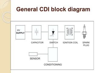
INDEX
1. Introduction
2. CDI Principle
3. General CDI Block Diagram
4. HV Supply
5. Capacitor
6. Switch
7. Sensor
8. Conditioning
9. Ignition Coil
10. Sparking Plug
11.First CDI Topology
12.Second CDI Topology
13.Advantages
14.Disadvantages
15.Conclusion
INTRODUCTION
 In the world of small motor, such as mopeds
or lawn movers the ignition system design is
based exclu-sively on CDI.
 In automobile CDI was in the past only used
in the replacement module market.
 Today, due to new standards of pollution
control, the CDI system is becoming one of
the most efficient choice available.
 The purpose of this paper is to analyze the
behavior of the CDI, the solutions we propose
today in small motor applications and the
state of the art in automotive.
CDI PRINCIPE
 The spark necessary to ignite the
air/petrol mixture in the combustion
chamber is produced by the CDI
module. This system consists of 7
stages.
General CDI block diagram
HV
SUPPLY
CAPACITOR SWITCH IGNITION COIL SPARK
PLUG
SENSOR
CONDITIONING
HV supply
 The HV supply differs from small motors
to automobiles. The small one or two
cylinder motors one or two stroke have a
fly-wheel which includes a supply
winding.
 This coil produces, after rectification, a
positive voltage variable between 100V
and 400V.
 The HV for an automobile CDI is
supplied by a DC/DC converter. This
stage produces generally 400V from the
12V battery voltage.
CAPACITOR
 The capacitor between 0.47 and 2µF
is used firstly, to store the charge from
the HV supply. During the second
phase of the ignition cycle the
capacitor is discharged through the
ignition circuit.
SWITCH
 The switch transfers the energy stored
in the capacitor to the primary of the
ignition coil. This function is carried
out by a SCR or a triac. The switch is
generally linked to a diode for the
reverse current.
SENSOR
 The goal of the sensor is to
synchronize the spark with the engine
rotation.
 For the small motor the sensor detects
a bump at each engine revolution.
 For car modules the sensor system
gives a pulse for each cyl-inder
ignition point.
Conditioning
 The conditioning is a very important stage which
must assume the following functions:
 Optimisation of the SCR gate current for all the
RPM range.
 Filtering of parasitic strikes occurring on the
sensor signal.
 For the most sophisticated small engine and all
the car systems, it has to ensure the correct lead
angle.
 This stage is realized using few passive
components for small motor modules, while for
automotive man-agement systems a
microprocessor is needed.
ignition coil
 The ignition coil is a step up
transformer which delivers high
voltage to the spark plug.
 This value can be between 5 and
20kV depending on the working
conditions.
spark plug
 The spark plug is the final element of
the ignition chain. High engine
efficiency and a complete gas com-
bustion are linked to a good spark
quality.
 Generally we estimate a minimum of
20 millijoules is necessary at spark
plug.
HOW DOES IT WORK?
 Two different topologies are possible.
First CDI topology
Figure shows the first possibility of discharge
circuit.
 When spark is needed a
current Ig is injected to the
SCR gate which then fires
the SCR. The SCR firing
initiates the capacitor
discharge which generates
an alternative current.

 The SCR conducts during
all the positive phases of
the discharge current while
the diode D acts for the
negative parts.
Discharge current through the
circuit
 CURRENT THROUGH
 THE IGNITION COIL
 PRIMARY 10A/div.
 SCR CURRENT
 10A/div.

 DIODE CURRENT
 10A/div.
Second topology
 C PR SC
ID
HV
SUPPLY
SCR D IPR SPARK
IG PLUG
 In the 2nd topology shown by figure
the SCR acts during the first part of
the current cycle until the capacitor
voltage reverse.
 Then the free wheeling diode D
conducts as long as there is energy
remaining on the primary coil.
Discharge current through the
circuit
SCR CURRENT
10A/div.
DIODE CURRENT
10A/div.
CURRENT
THROUGH
THE IGNITIONCOIL
PRIMARY
10A/div.
SMALL ENGINE SYSTEM
 Figure shows the topology we have chosen for
the small motor CDI module.
 The supply coil generates an alternating voltage,
in which the positive parts are rectified by D2 and
the negative parts are clamped by D3.
 This circuit configuration allows the designer to
use 400V diodes for D2 and D3 instead of 1000V
user in other design.
 The capacitance C1 is loaded by the positive
rectified current.
Small motor DCI principle
circuit
 STOP
D1 D2
supply coil D3
fly wheel
R
sensor c2
C1
SCR
spark
plug
D4
Advantages
 A CDI system has a short charging time, a fast
voltage rise (between 3 ~ 10 kV/μs) compared to
typical inductive systems (300 ~ 500 V/μs) and a
short spark duration limited to about 50-80 µs.
 The fast voltage rise makes CDI systems
insensitive to shunt resistance, but the limited
spark duration can for some applications be too
short to provide reliable ignition.
 The insensitivity to shunt resistance and the ability
to fire multiple sparks can provide improved cold
starting ability.
Disadvantages
 Since the CDI system only provides a
short spark, it's also possible to combine
this ignition system with ionization
measurement.
 This is done by connecting a low voltage
(about 80 V) to the spark plug, except
when fired. The current flow over the
spark plug can then be used to calculate
the temperature and pressure inside the
cylinder
CONCLUSION
 Capacitive discharge ignition systems
are the only choice for the small
engines.
 They are also found fre-quently in
racing car engine management
computer.
 For the future the CDI could be the
solution meet the new anti-pollution
Capasitor discharge ignition ppt

Capasitor discharge ignition ppt

  • 2.
    INDEX 1. Introduction 2. CDIPrinciple 3. General CDI Block Diagram 4. HV Supply 5. Capacitor 6. Switch 7. Sensor 8. Conditioning 9. Ignition Coil 10. Sparking Plug 11.First CDI Topology 12.Second CDI Topology 13.Advantages 14.Disadvantages 15.Conclusion
  • 3.
    INTRODUCTION  In theworld of small motor, such as mopeds or lawn movers the ignition system design is based exclu-sively on CDI.  In automobile CDI was in the past only used in the replacement module market.  Today, due to new standards of pollution control, the CDI system is becoming one of the most efficient choice available.  The purpose of this paper is to analyze the behavior of the CDI, the solutions we propose today in small motor applications and the state of the art in automotive.
  • 4.
    CDI PRINCIPE  Thespark necessary to ignite the air/petrol mixture in the combustion chamber is produced by the CDI module. This system consists of 7 stages.
  • 5.
    General CDI blockdiagram HV SUPPLY CAPACITOR SWITCH IGNITION COIL SPARK PLUG SENSOR CONDITIONING
  • 6.
    HV supply  TheHV supply differs from small motors to automobiles. The small one or two cylinder motors one or two stroke have a fly-wheel which includes a supply winding.  This coil produces, after rectification, a positive voltage variable between 100V and 400V.  The HV for an automobile CDI is supplied by a DC/DC converter. This stage produces generally 400V from the 12V battery voltage.
  • 7.
    CAPACITOR  The capacitorbetween 0.47 and 2µF is used firstly, to store the charge from the HV supply. During the second phase of the ignition cycle the capacitor is discharged through the ignition circuit.
  • 8.
    SWITCH  The switchtransfers the energy stored in the capacitor to the primary of the ignition coil. This function is carried out by a SCR or a triac. The switch is generally linked to a diode for the reverse current.
  • 9.
    SENSOR  The goalof the sensor is to synchronize the spark with the engine rotation.  For the small motor the sensor detects a bump at each engine revolution.  For car modules the sensor system gives a pulse for each cyl-inder ignition point.
  • 10.
    Conditioning  The conditioningis a very important stage which must assume the following functions:  Optimisation of the SCR gate current for all the RPM range.  Filtering of parasitic strikes occurring on the sensor signal.  For the most sophisticated small engine and all the car systems, it has to ensure the correct lead angle.  This stage is realized using few passive components for small motor modules, while for automotive man-agement systems a microprocessor is needed.
  • 11.
    ignition coil  Theignition coil is a step up transformer which delivers high voltage to the spark plug.  This value can be between 5 and 20kV depending on the working conditions.
  • 12.
    spark plug  Thespark plug is the final element of the ignition chain. High engine efficiency and a complete gas com- bustion are linked to a good spark quality.  Generally we estimate a minimum of 20 millijoules is necessary at spark plug.
  • 13.
    HOW DOES ITWORK?  Two different topologies are possible.
  • 14.
    First CDI topology Figureshows the first possibility of discharge circuit.
  • 15.
     When sparkis needed a current Ig is injected to the SCR gate which then fires the SCR. The SCR firing initiates the capacitor discharge which generates an alternative current.   The SCR conducts during all the positive phases of the discharge current while the diode D acts for the negative parts.
  • 16.
    Discharge current throughthe circuit  CURRENT THROUGH  THE IGNITION COIL  PRIMARY 10A/div.  SCR CURRENT  10A/div.   DIODE CURRENT  10A/div.
  • 17.
    Second topology  CPR SC ID HV SUPPLY SCR D IPR SPARK IG PLUG
  • 18.
     In the2nd topology shown by figure the SCR acts during the first part of the current cycle until the capacitor voltage reverse.  Then the free wheeling diode D conducts as long as there is energy remaining on the primary coil.
  • 19.
    Discharge current throughthe circuit SCR CURRENT 10A/div. DIODE CURRENT 10A/div. CURRENT THROUGH THE IGNITIONCOIL PRIMARY 10A/div.
  • 20.
    SMALL ENGINE SYSTEM Figure shows the topology we have chosen for the small motor CDI module.  The supply coil generates an alternating voltage, in which the positive parts are rectified by D2 and the negative parts are clamped by D3.  This circuit configuration allows the designer to use 400V diodes for D2 and D3 instead of 1000V user in other design.  The capacitance C1 is loaded by the positive rectified current.
  • 21.
    Small motor DCIprinciple circuit  STOP D1 D2 supply coil D3 fly wheel R sensor c2 C1 SCR spark plug D4
  • 22.
    Advantages  A CDIsystem has a short charging time, a fast voltage rise (between 3 ~ 10 kV/μs) compared to typical inductive systems (300 ~ 500 V/μs) and a short spark duration limited to about 50-80 µs.  The fast voltage rise makes CDI systems insensitive to shunt resistance, but the limited spark duration can for some applications be too short to provide reliable ignition.  The insensitivity to shunt resistance and the ability to fire multiple sparks can provide improved cold starting ability.
  • 23.
    Disadvantages  Since theCDI system only provides a short spark, it's also possible to combine this ignition system with ionization measurement.  This is done by connecting a low voltage (about 80 V) to the spark plug, except when fired. The current flow over the spark plug can then be used to calculate the temperature and pressure inside the cylinder
  • 24.
    CONCLUSION  Capacitive dischargeignition systems are the only choice for the small engines.  They are also found fre-quently in racing car engine management computer.  For the future the CDI could be the solution meet the new anti-pollution