Learning Objectives
1. Introductionto Ignition Systems
2. Battery Ignition System
3. Magneto Ignition System
4. Capacitor Discharge Ignition
5. Electronics Ignition Control
6. Distributor Vs Distributor less Ignition
3.
Ignition System Functions
Producesupto 30000V spark across plugs
Distribute spark to each plug in correct sequence
Times the sparks as it occurs so piston is near top dead centre
Varies spark timing with load, speed and other conditions
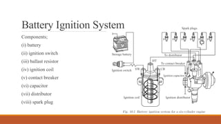
Battery Ignition System
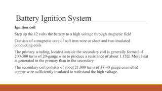
Ignitioncoil
Step up the 12 volts the battery to a high voltage through magnetic field
Consists of a magnetic core of soft iron wire or sheet and two insulated
conducting coils
The primary winding, located outside the secondary coil is generally formed of
200-300 turns of 20-gauge wire to produce a resistance of about 1.15Ω. More heat
is generated in the primary than in the secondary
The secondary coil consists of about 21,000 turns of 38-40 gauge enamelled
copper wire sufficiently insulated to withstand the high voltage.
7.
Battery Ignition System
BallastResistor
Prevent injury to the spark coil by overheating if the engine should be operated
for a long time at low speed or should be stalled with the breaker in the closed
position.
Electrical resistance increases very rapidly if a certain temperature is exceeded.
This holds the primary current down to a safe value.
Capacitor (Condensor)
Suppresses most of the arcing as the contact breakers open.
This allows for a more rapid break of primary current and hence a more rapid
collapse of coil magnetism, which produces a higher voltage output.
8.
Battery Ignition System
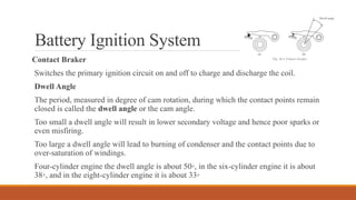
ContactBraker
Switches the primary ignition circuit on and off to charge and discharge the coil.
Dwell Angle
The period, measured in degree of cam rotation, during which the contact points remain
closed is called the dwell angle or the cam angle.
Too small a dwell angle will result in lower secondary voltage and hence poor sparks or
even misfiring.
Too large a dwell angle will lead to burning of condenser and the contact points due to
over-saturation of windings.
Four-cylinder engine the dwell angle is about 50◦, in the six-cylinder engine it is about
38◦, and in the eight-cylinder engine it is about 33◦
9.
Battery Ignition System
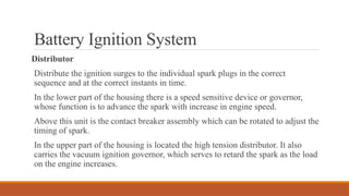
Distributor
Distributethe ignition surges to the individual spark plugs in the correct
sequence and at the correct instants in time.
In the lower part of the housing there is a speed sensitive device or governor,
whose function is to advance the spark with increase in engine speed.
Above this unit is the contact breaker assembly which can be rotated to adjust the
timing of spark.
In the upper part of the housing is located the high tension distributor. It also
carries the vacuum ignition governor, which serves to retard the spark as the load
on the engine increases.
10.
Battery Ignition System
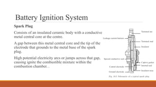
SparkPlug
Consists of an insulated ceramic body with a conductive
metal central core at the centre.
A gap between this metal central core and the tip of the
electrode that grounds to the metal base of the spark
plug.
High potential electricity arcs or jumps across that gap,
causing ignite the combustible mixture within the
combustion chamber. .
11.
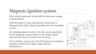
Magneto Ignition system
Ownelectric generator to provide the necessary energy
without battery.
With the help of a cam, the primary circuit flux is
changed and a high voltage is produced in the secondary
circuit.
the cranking speed at start is low the current generated
by the magneto is quite small. As the engine speed
increases the flow of current also increases.
Two wheelers, racing cars, aircraft engines use magneto
ignition system due to light weight and less
maintenance.
13.
Limitations of conventionalIgnition
The decrease in available voltage as the engine speed increases due to limitations
in the current switching capability of the breaker system and the decreasing time
available to build up the stored energy in the primary coil.
Due to their high current load, the breaker points are subjected to electrical wear
in addition to mechanical wear which results in short maintenance intervals.
Legislation requires stringent emission limits, which means the ignition timing
must stay in tune for a long period of time.
Solution:
Electronic Ignition (Transistorized )
14.
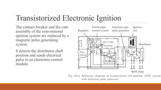
Transistorized Electronic Ignition
Thecontact breaker and the cam
assembly of the conventional
ignition system are replaced by a
magnetic pulse generating
system.
It detects the distributor shaft
position and sends electrical
pulse to an electronic control
module.
15.
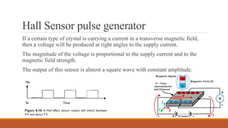
Hall Sensor pulsegenerator
If a certain type of crystal is carrying a current in a transverse magnetic field,
then a voltage will be produced at right angles to the supply current.
The magnitude of the voltage is proportional to the supply current and to the
magnetic field strength.
The output of this sensor is almost a square wave with constant amplitude.
16.
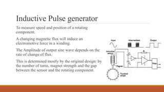
Inductive Pulse generator
Tomeasure speed and position of a rotating
component.
A changing magnetic flux will induce an
electromotive force in a winding.
The Amplitude of output sine wave depends on the
rate of change of flux.
This is determined mostly by the original design: by
the number of turns, magnet strength and the gap
between the sensor and the rotating component.
17.
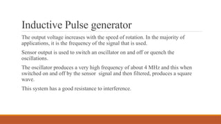
Inductive Pulse generator
Theoutput voltage increases with the speed of rotation. In the majority of
applications, it is the frequency of the signal that is used.
Sensor output is used to switch an oscillator on and off or quench the
oscillations.
The oscillator produces a very high frequency of about 4 MHz and this when
switched on and off by the sensor signal and then filtered, produces a square
wave.
This system has a good resistance to interference.
18.
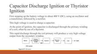
Capacitor Discharge Ignitionor Thyristor
Ignition
First stepping up the battery voltage to about 400 V (DC), using an oscillator and
a transformer, followed by a rectifier.
This high voltage is used to charge a capacitor.
At the point of ignition, the capacitor is discharged through the primary winding
of a coil, often by use of a thyristor.
This rapid discharge through the coil primary will produce a very high voltage
output from the secondary winding.
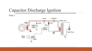
Capacitor Discharge Ignition
Typically,the rise time for CDI is 3–10 kV/s as compared with the pure inductive
system, which is 300–500 V/s.
Because of the fast capacitive discharge, the spark is strong but short (0.1 to 0.3
ms) which leads to ignition failure during lean mixture operating conditions.
This is the main disadvantage of the CDI system.
CDIs are commonly found on motorbikes and scooters.
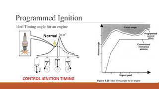
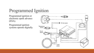
Programmed Ignition
sensor informationregarding the operating requirements of a particular engine is
obtained from rigorous testing on an engine under various operating conditions
and stored in read only memory (ROM)
Benefits
(i) The ignition timing can be accurately matched to the individual application
under a range of various operating conditions.
(ii) Control inputs like coolant temperature and ambient air temperature can be
used. Other inputs such as engine knock can be taken into account.
(iii) Starting is improved, fuel consumption as well as emissions are reduced, and
idle control is better.
(iv) The number of wearing components is considerably reduced in this system
24.
Programmed Ignition
The dischas 34 teeth spaced at 10 degrees intervals around the periphery of the
disc and has two teeth missing at 180 degrees, and at a known position before
TDC.
When a tooth of the reluctor disc passes the core of the sensor the reluctance of
the mag
netic circuit is changed, which induces a voltage in the winding, because
the frequency of the wave form is proportional to the engine speed.
The missing tooth causes a missed output wave, which is used to determine
engine position.
25.
Programmed Ignition
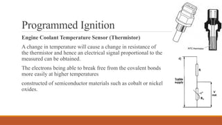
Engine CoolantTemperature Sensor (Thermistor)
A change in temperature will cause a change in resistance of
the thermistor and hence an electrical signal proportional to the
measured can be obtained.
The electrons being able to break free from the covalent bonds
more easily at higher temperatures
constructed of semiconductor materials such as cobalt or nickel
oxides.
26.
Programmed Ignition
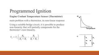
Engine CoolantTemperature Sensor (Thermistor)
main problem with a thermistor, its non-linear response
Using a suitable bridge circuit, it is possible to produce
non-linearity that will partially compensate for the
thermistor’s non-linearity.
27.
Programmed Ignition
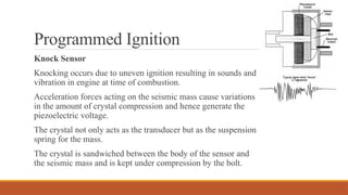
Knock Sensor
Knockingoccurs due to uneven ignition resulting in sounds and
vibration in engine at time of combustion.
Acceleration forces acting on the seismic mass cause variations
in the amount of crystal compression and hence generate the
piezoelectric voltage.
The crystal not only acts as the transducer but as the suspension
spring for the mass.
The crystal is sandwiched between the body of the sensor and
the seismic mass and is kept under compression by the bolt.
28.
Programmed Ignition
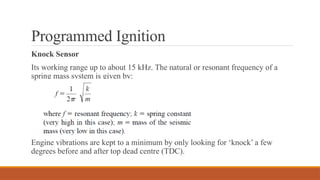
Knock Sensor
Itsworking range up to about 15 kHz. The natural or resonant frequency of a
spring mass system is given by:
Engine vibrations are kept to a minimum by only looking for ‘knock’ a few
degrees before and after top dead centre (TDC).
29.
Programmed Ignition
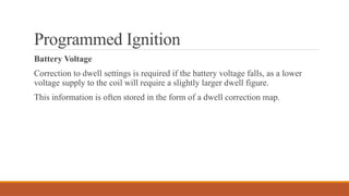
Battery Voltage
Correctionto dwell settings is required if the battery voltage falls, as a lower
voltage supply to the coil will require a slightly larger dwell figure.
This information is often stored in the form of a dwell correction map.
30.
Programmed Ignition
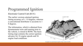
Electronic ControlUnit (ECU)
The earlier versions attained ignition
timing accuracy of ± 1.8 degrees, whereas
a conventional distributor is accurate to ±
8 degrees.
The information, which is obtained from
dynamometer tests and running tests in
the vehicle, is stored in ROM. The basic
timing map contains the correct ignition
advance for 16 engine speeds and 16
engine load conditions
31.
Programmed Ignition
A separatethree dimensional map, containing eight speed and eight temperature
locations, is also used to incorporate corrections for engine coolant temperature
to the basic timing settings.
This improves driveability and can be used to decrease the warm-up time of the
engine.
The ECU also incorporates correc
tions to the dwell angle, due to changes in
battery voltage and also as a function of engine speed to provide constant energy
output. A slightly longer dwell is required for a lower battery voltage and a
slightly shorter dwell for higher voltage.
33.
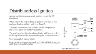
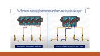
Distributorless Ignition
Almost similarto programmed ignition except the HT
distributor
When one of the coils is fired, a spark is delivered to two
engine cylinders, either 1 and 4, or 2 and 3.
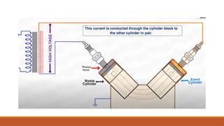
The spark delivered to the cylinder on the compression
stroke will ignite the mixture as normal.
The spark produced in the other cylinder will have no effect,
as this cylinder will be just completing its exhausted stroke.
Uses Concept of wasted spark.
https://www.youtube.com/watch?v=PHla1hR2EG0&ab_cha
nnel=RatchetsAndWrenches