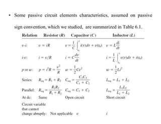
This document provides an introduction to capacitors and inductors. It discusses how capacitors store electric charge and inductors store magnetic energy. Key points include:
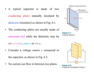
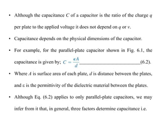
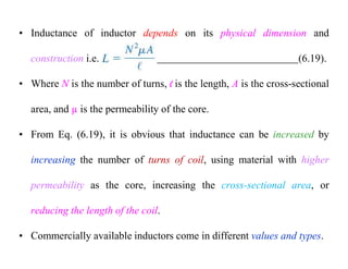
- Capacitors oppose changes in voltage by accumulating electric charge on conducting plates separated by a dielectric. The capacitance depends on the plate area, distance between plates, and dielectric material.
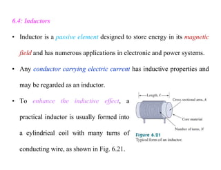
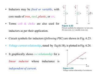
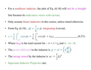
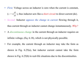
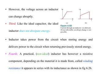
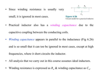
- Inductors oppose changes in current. They are formed from coils of conducting wire that generate magnetic fields when current flows.
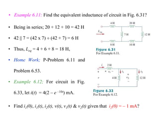
- Circuit analysis techniques used for resistors can also be applied to circuits containing capacitors and inductors. Energy can be stored in the electric fields of capacitors and magnetic fields of inductors.
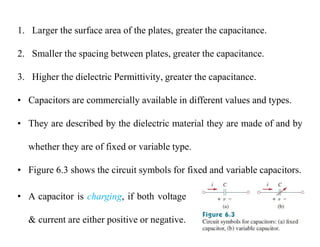
- Capacitors and inductors


![[Deck] What's New in Spark-Iceberg Integration via DSV2.pptx](https://cdn.slidesharecdn.com/ss_thumbnails/deckwhatsnewinspark-icebergintegrationviadsv2-260210005337-25955b12-thumbnail.jpg?width=640&height=640&fit=bounds)


