![CONTROL ENGINEERING
Course Code 18ME71 CIE Marks 40
Teaching Hours / Week (L:T:P) 3:0:0 SEE Marks 60
Credits 03 Exam Hours 03
[AS PER CHOICE BASED CREDIT SYSTEM (CBCS) SCHEME]
SEMESTER – VII
Dr. Mohammed Imran
B. E. IN MECHANICAL ENGINEERING](https://image.slidesharecdn.com/controlengineeringmodule-1part-a-220101134136/75/Control-engineering-module-1-part-a-18me71-1-2048.jpg)
![CONTROL ENGINEERING
Course Code 18ME71 CIE Marks 40
Teaching Hours / Week (L:T:P) 3:0:0 SEE Marks 60
Credits 03 Exam Hours 03
[AS PER CHOICE BASED CREDIT SYSTEM (CBCS) SCHEME]
SEMESTER – VII
Dr. Mohammed Imran
B. E. IN MECHANICAL ENGINEERING](https://image.slidesharecdn.com/controlengineeringmodule-1part-a-220101134136/75/Control-engineering-module-1-part-a-18me71-2-2048.jpg)
![1.2 Classification Of Control Systems
Type 3: From the analysis point of view, control system can be classified into
4. Single input - Single Output [SISO] and Multiple Input Multiple-Output
[MIMO] control systems
A control system in which there is one input and one output is called single
input and single output control system.
A control system in which there are multiple input and multiple output is known
Cont………
A control system in which there are multiple input and multiple output is known
as multiple input and multiple output control systems.
Type 4 : Based on the presence of feedback
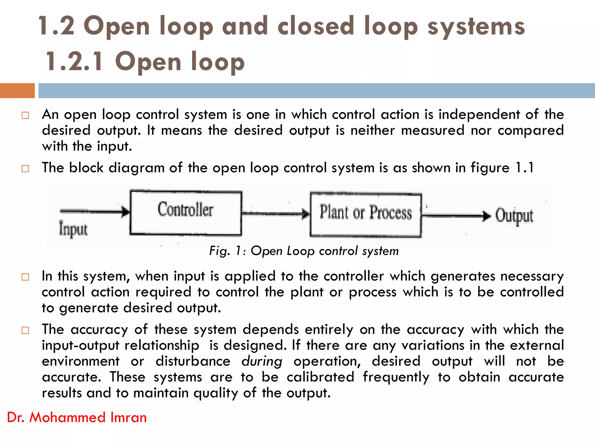
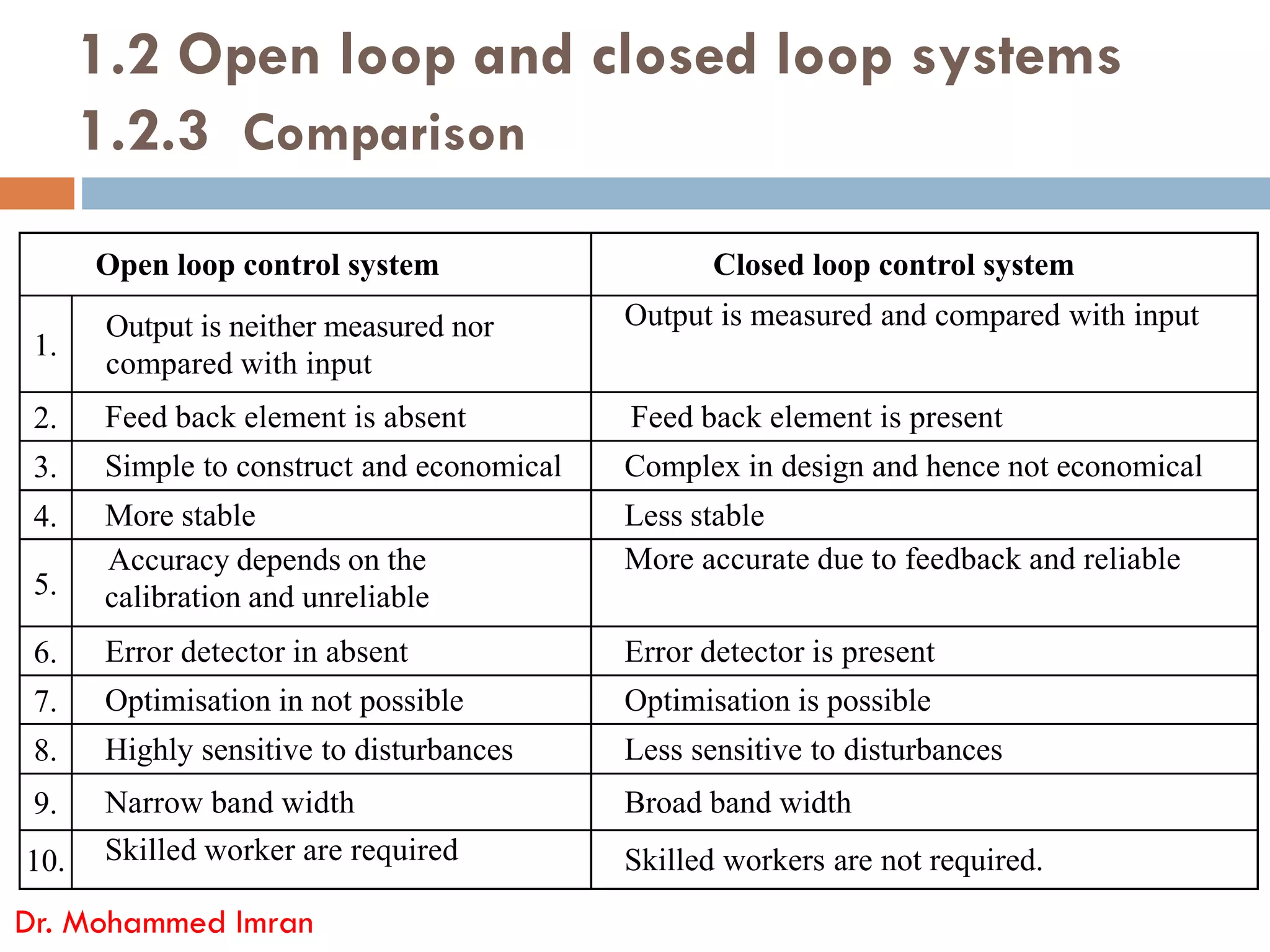
Open Loop control system - A control system in which control action is
independent of the desired output is known as open loop control system.
(Feedback is absent)
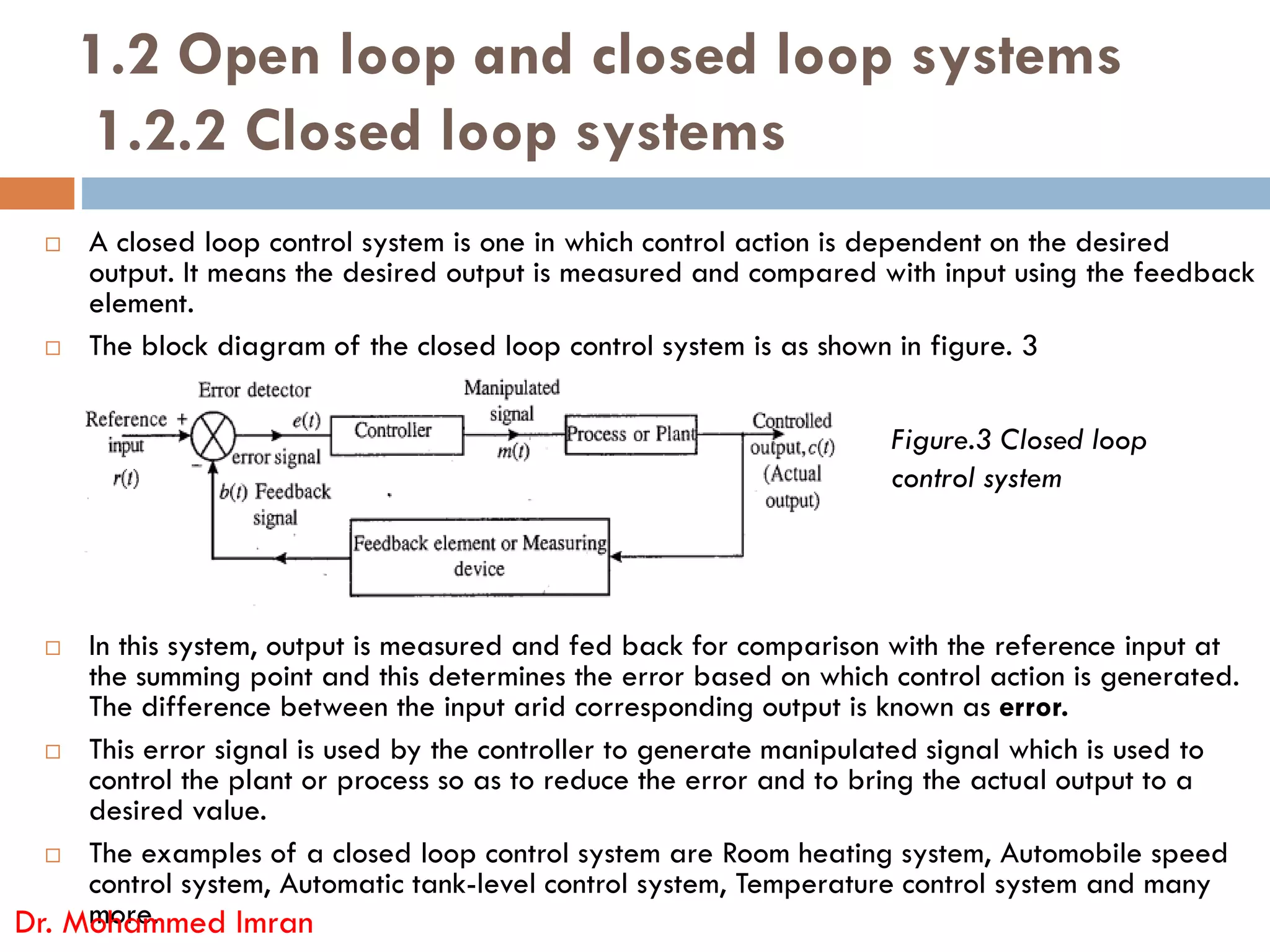
Closed Loop-control system - A control system in which control action in
dependent on the. desired output is Ic.nowh as closed-loop control system.
(Feedback is present)
Dr. Mohammed Imran](https://image.slidesharecdn.com/controlengineeringmodule-1part-a-220101134136/75/Control-engineering-module-1-part-a-18me71-20-2048.jpg)
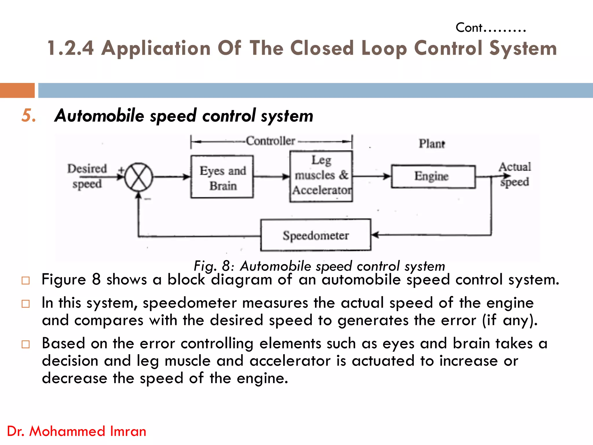

The document outlines a control engineering course (code 18ME71) designed for mechanical engineering students, focusing on modern control theory and system analysis skills. The course encompasses various control system components, their applications, and classifications, detailing the objectives, learning outcomes, and curriculum structure. It also discusses the significance of control systems in everyday life, industry, and advanced technologies.