Download as PDF, PPTX


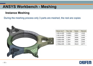

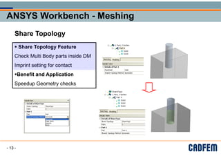


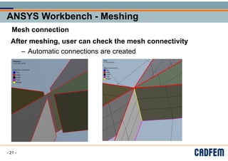


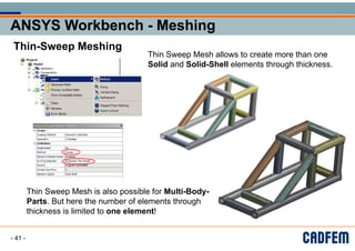


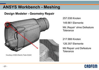


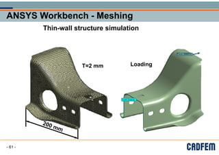


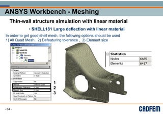


This document discusses various meshing techniques in ANSYS Workbench including: - Direct meshing which allows more control over the meshing order of multiple bodies compared to automated meshing. - Instance meshing which only meshes a single instance of identical parts to reduce meshing time. - Share topology which identifies matching faces and edges between connected parts to improve mesh quality at interfaces. - Mesh connections which define the connectivity between meshes of different parts automatically during meshing. - Advanced sizing functions which allow non-uniform mesh sizes to be defined across a model.


![[第2版]Python機械学習プログラミング 第11章](https://cdn.slidesharecdn.com/ss_thumbnails/11-181212011918-thumbnail.jpg?width=640&height=640&fit=bounds)


![[DL輪読会]YOLO9000: Better, Faster, Stronger](https://cdn.slidesharecdn.com/ss_thumbnails/dlreadingpaper20170804-170803075138-thumbnail.jpg?width=640&height=640&fit=bounds)

![[DL輪読会]HoloGAN: Unsupervised learning of 3D representations from natural images](https://cdn.slidesharecdn.com/ss_thumbnails/hologanslideshare-190906010228-thumbnail.jpg?width=640&height=640&fit=bounds)


![Attack surfaces and attack tress[inform]](https://cdn.slidesharecdn.com/ss_thumbnails/lecture03-260108015941-a4dee53b-thumbnail.jpg?width=640&height=640&fit=bounds)

