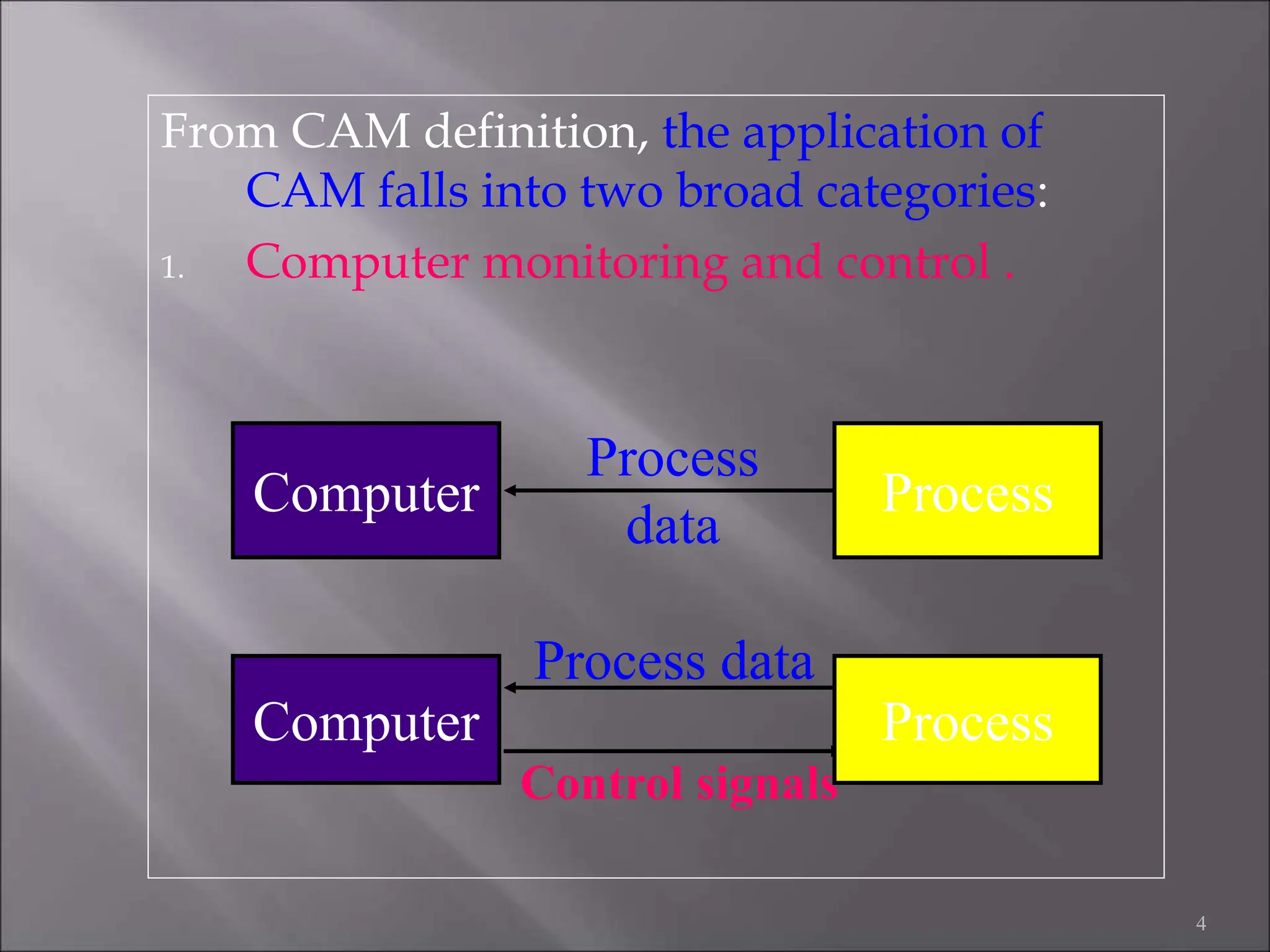
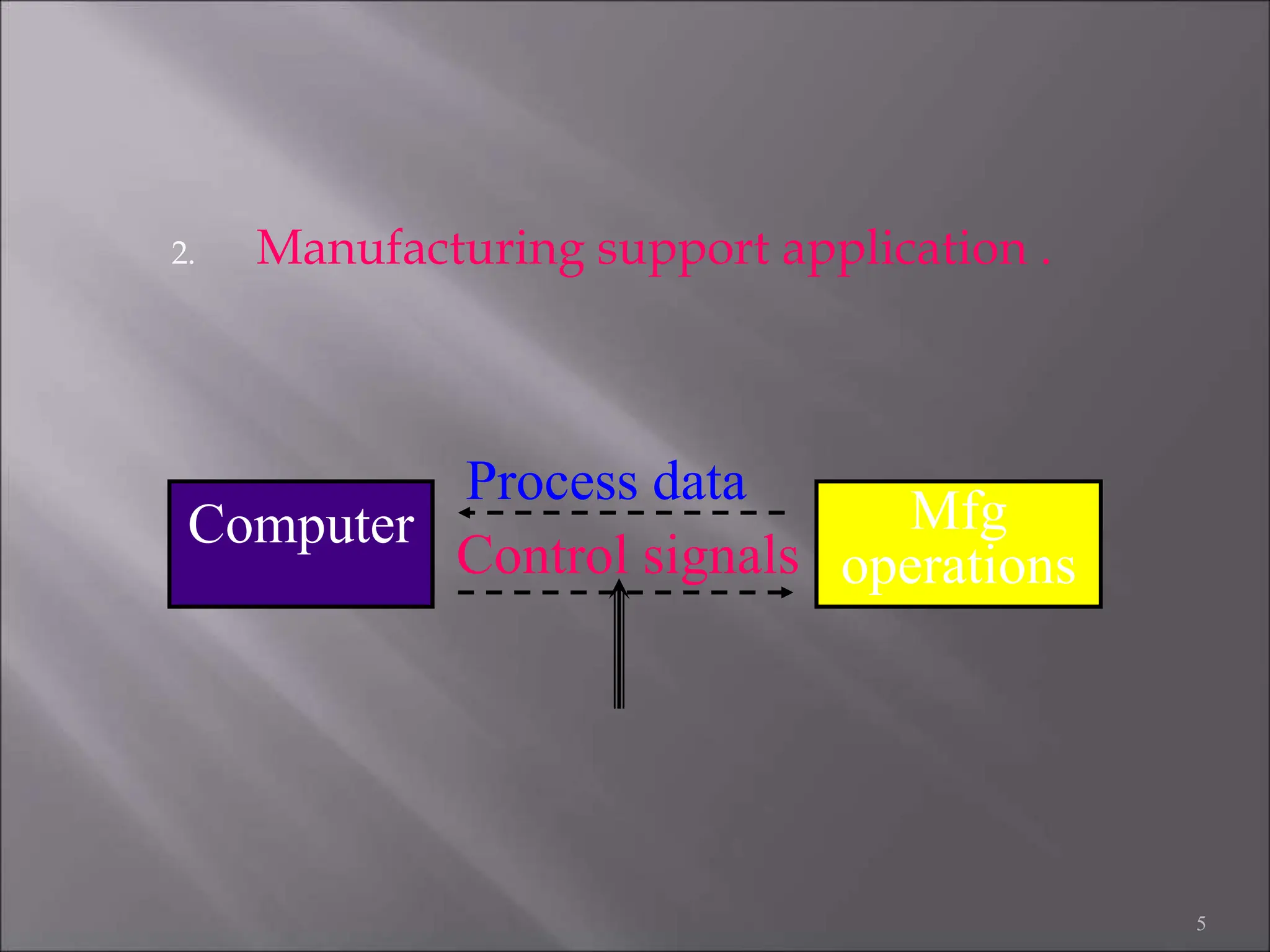
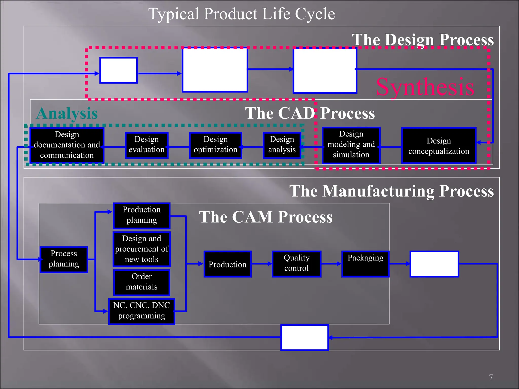
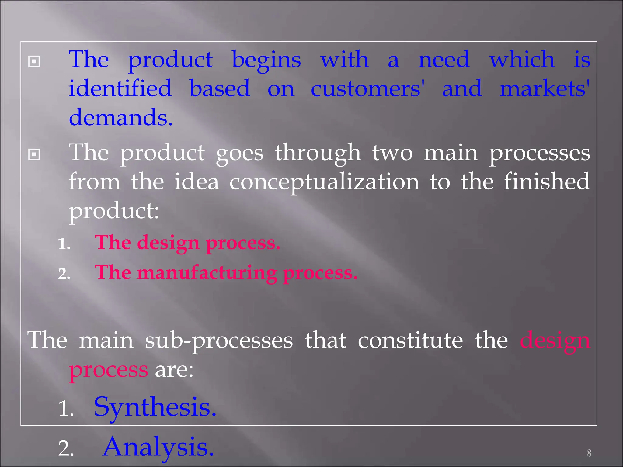
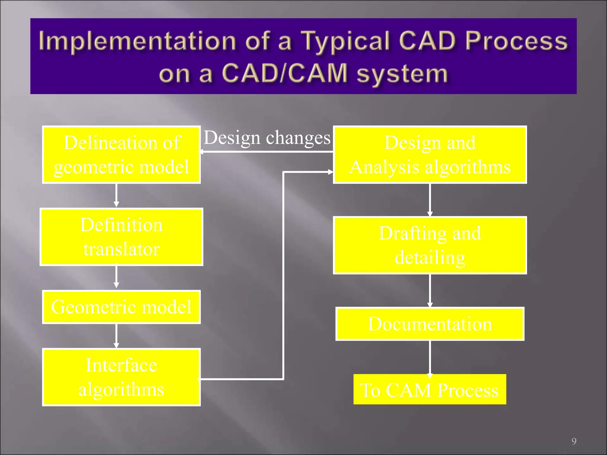
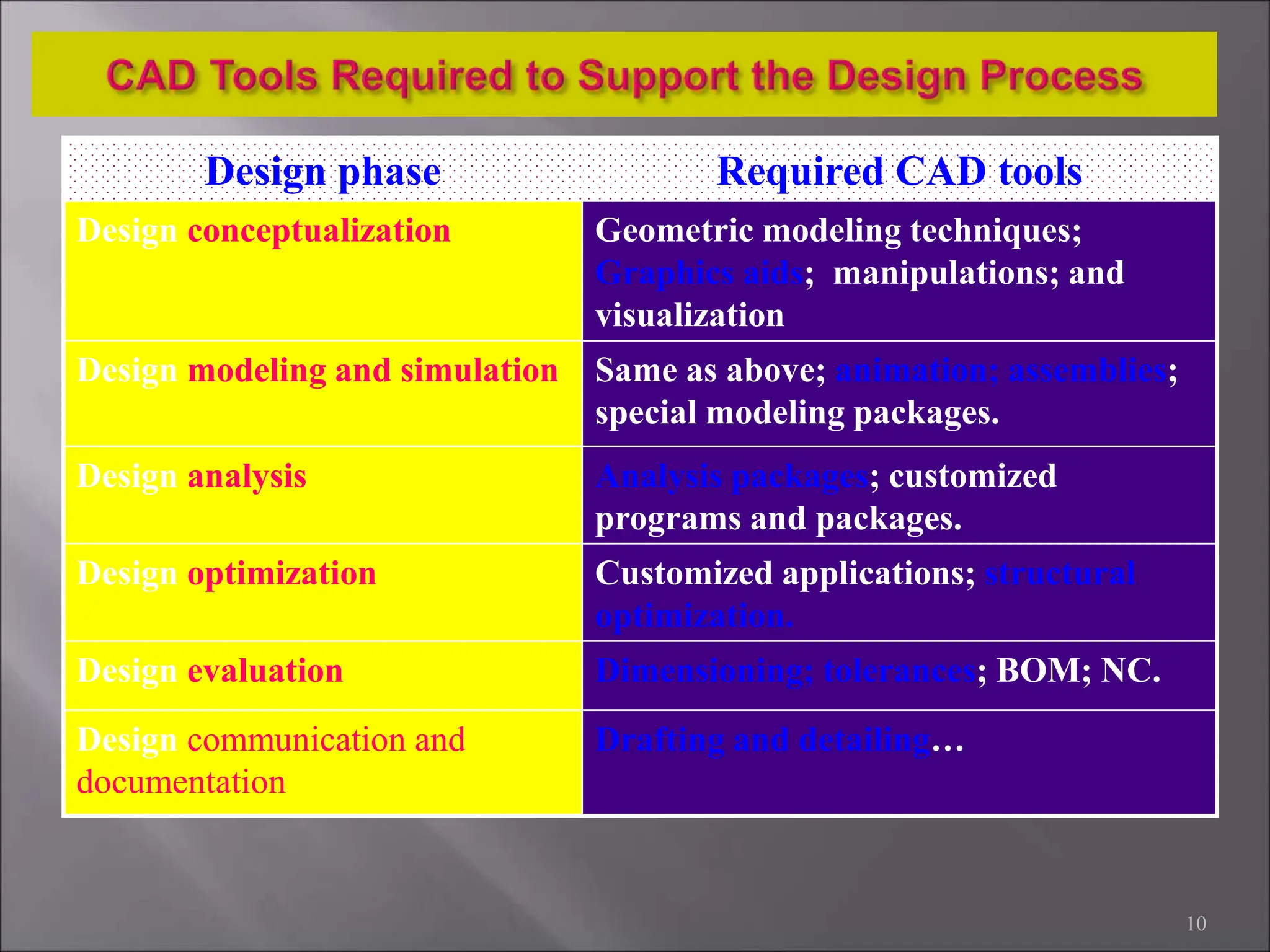
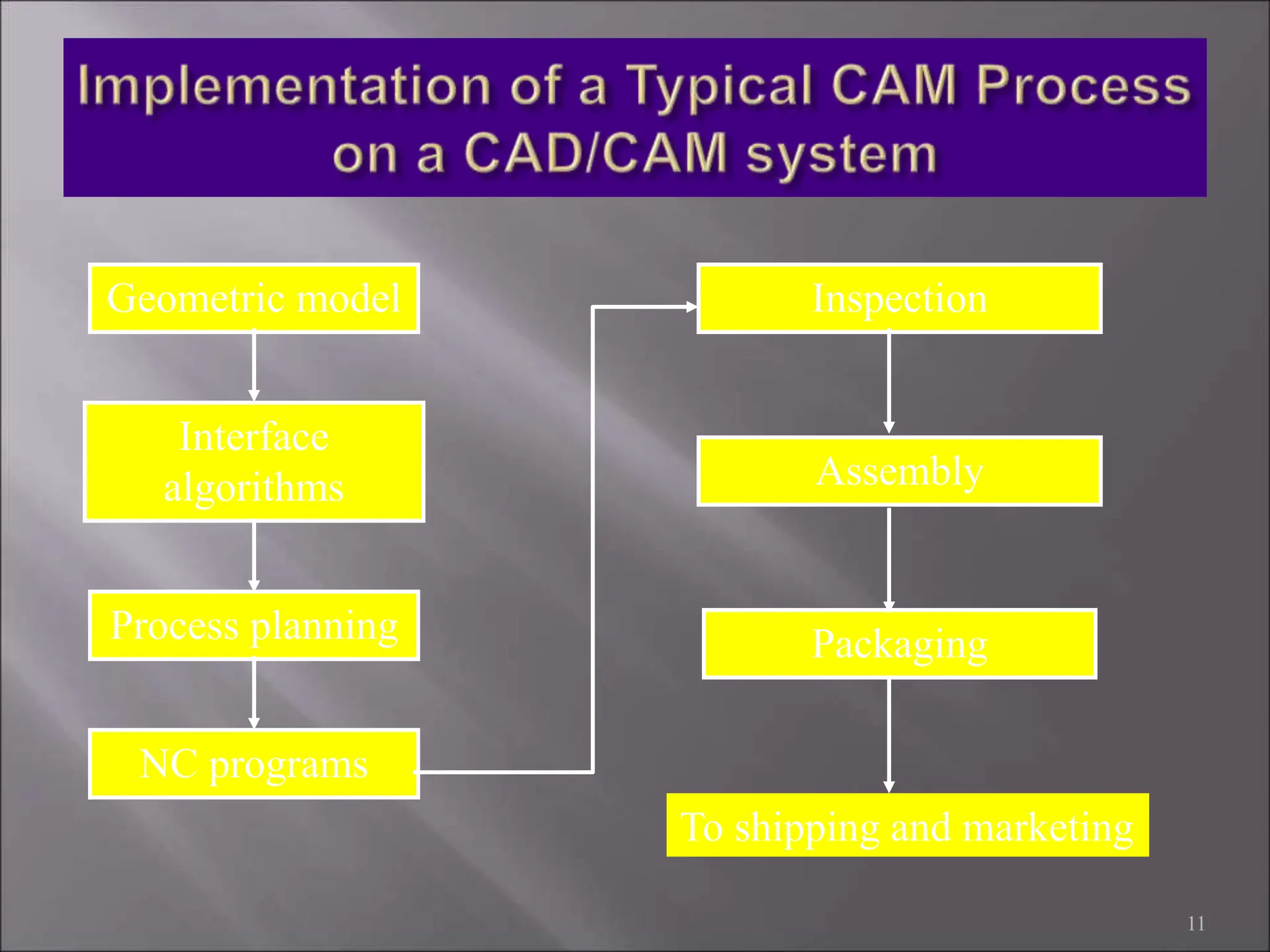
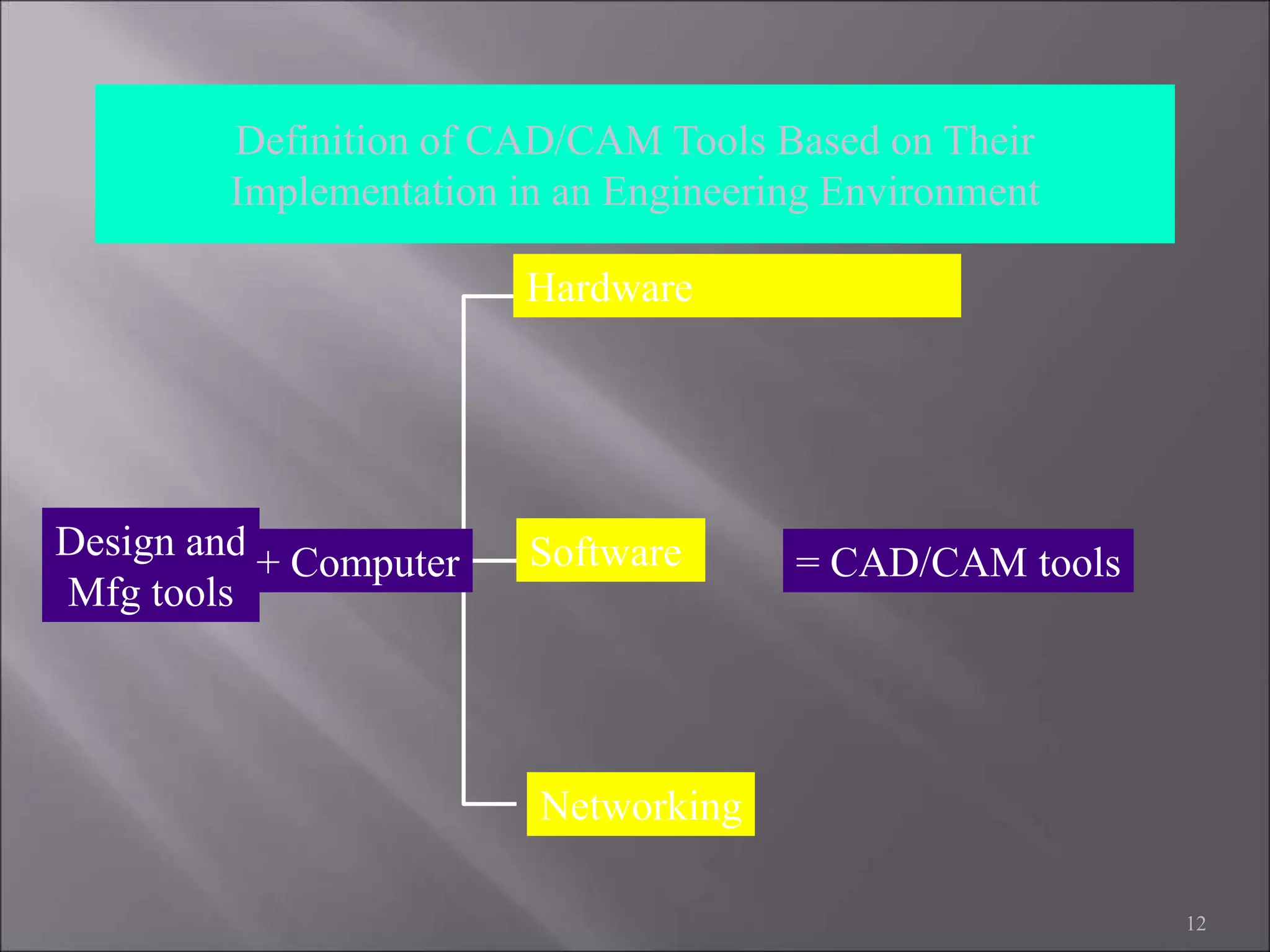
1
 CAD/CAM = Computer Aided Design and
Computer Aided Manufacturing. It is the
technology concerned with the use of
computers to perform design and
manufacturing functions.
2
 CAD can be defined as the use of computer
systems to perform certain functions in the
design process.
 CAM is the use of computer systems to plan,
manage and control the operations of
manufacturing plant through either direct or
indirect computer interface with the plant’s
production resources.
3
From CAM definition, the application of
CAM falls into two broad categories:
1. Computer monitoring and control .
4
Computer Process
Process
data
Control signals
Computer Process
Process data
2. Manufacturing support application .
5
Control signals
Computer Mfg
operations
Process data
In order to establish the scope and definition
of CAD/CAM in an engineering environment
and identify existing and future related tools,
a study of a typical product cycle is necessary.
The following Figure shows a flowchart of
such a cycle.
6
7
The Manufacturing Process
The Design Process
Synthesis
Analysis The CAD Process
The CAM Process
Design
needs
Design
definitions,
specifications,
and requirements
Collecting
relevant design
information and
feasibility study
Design
conceptualization
Design
modeling and
simulation
Design
analysis
Design
optimization
Design
evaluation
Design
documentation and
communication
Process
planning
Order
materials
Design and
procurement of
new tools
Production
planning
NC, CNC, DNC
programming
Production
Quality
control
Packaging
Marketing
Shipping
Typical Product Life Cycle
 The product begins with a need which is
identified based on customers' and markets'
demands.
 The product goes through two main processes
from the idea conceptualization to the finished
product:
1. The design process.
2. The manufacturing process.
The main sub-processes that constitute the design
process are:
1. Synthesis.
2. Analysis. 8
9
Delineation of
geometric model
Definition
translator
Geometric model
Design and
Analysis algorithms
Drafting and
detailing
Documentation
To CAM Process
Interface
algorithms
Design changes
10
Design phase Required CAD tools
Design conceptualization Geometric modeling techniques;
Graphics aids; manipulations; and
visualization
Design modeling and simulation Same as above; animation; assemblies;
special modeling packages.
Design analysis Analysis packages; customized
programs and packages.
Design optimization Customized applications; structural
optimization.
Design evaluation Dimensioning; tolerances; BOM; NC.
Design communication and
documentation
Drafting and detailing…
11
Geometric model
Interface
algorithms
Process planning
Inspection
Assembly
Packaging
To shipping and marketing
NC programs
12
Definition of CAD/CAM Tools Based on Their
Implementation in an Engineering Environment
Design and
Mfg tools
Hardware
Software = CAD/CAM tools
Networking
+ Computer
Automation can be defined as the
technology concerned with the application
of complex mechanical, electronic, and
computer-based systems in the operation
and control of manufacturing systems.
13
14
Most of the automated production systems implemented today
make use of computers. CAD/CAM in addition to its particular
emphasis on the use of computer technology, is also
distinguished by the fact that it includes not only the
manufacturing operations but also the design and planning
functions that precede manufacturing.
To emphasize the differences in scope between automation and
CAD/CAM, consider the following mathematical model:
Computer Technology in Automation
 Greater flexibility.
 Reduced lead times.
 Reduced inventories.
 Increased Productivity.
 Improved customer
service.
 Improved quality.
 Improved
communications with
suppliers.
15
• Better product design.
• Greater manufacturing
control.
• Supported integration.
• Reduced costs.
• Increased utilization.
• Reduction of machine
tools.
• Less floor space.

Computer Aided Design and Computer Aided Manufacturing

  • 1.
  • 2.
     CAD/CAM =Computer Aided Design and Computer Aided Manufacturing. It is the technology concerned with the use of computers to perform design and manufacturing functions. 2
  • 3.
     CAD canbe defined as the use of computer systems to perform certain functions in the design process.  CAM is the use of computer systems to plan, manage and control the operations of manufacturing plant through either direct or indirect computer interface with the plant’s production resources. 3
  • 4.
    From CAM definition,the application of CAM falls into two broad categories: 1. Computer monitoring and control . 4 Computer Process Process data Control signals Computer Process Process data
  • 5.
    2. Manufacturing supportapplication . 5 Control signals Computer Mfg operations Process data
  • 6.
    In order toestablish the scope and definition of CAD/CAM in an engineering environment and identify existing and future related tools, a study of a typical product cycle is necessary. The following Figure shows a flowchart of such a cycle. 6
  • 7.
    7 The Manufacturing Process TheDesign Process Synthesis Analysis The CAD Process The CAM Process Design needs Design definitions, specifications, and requirements Collecting relevant design information and feasibility study Design conceptualization Design modeling and simulation Design analysis Design optimization Design evaluation Design documentation and communication Process planning Order materials Design and procurement of new tools Production planning NC, CNC, DNC programming Production Quality control Packaging Marketing Shipping Typical Product Life Cycle
  • 8.
     The productbegins with a need which is identified based on customers' and markets' demands.  The product goes through two main processes from the idea conceptualization to the finished product: 1. The design process. 2. The manufacturing process. The main sub-processes that constitute the design process are: 1. Synthesis. 2. Analysis. 8
  • 9.
    9 Delineation of geometric model Definition translator Geometricmodel Design and Analysis algorithms Drafting and detailing Documentation To CAM Process Interface algorithms Design changes
  • 10.
    10 Design phase RequiredCAD tools Design conceptualization Geometric modeling techniques; Graphics aids; manipulations; and visualization Design modeling and simulation Same as above; animation; assemblies; special modeling packages. Design analysis Analysis packages; customized programs and packages. Design optimization Customized applications; structural optimization. Design evaluation Dimensioning; tolerances; BOM; NC. Design communication and documentation Drafting and detailing…
  • 11.
  • 12.
    12 Definition of CAD/CAMTools Based on Their Implementation in an Engineering Environment Design and Mfg tools Hardware Software = CAD/CAM tools Networking + Computer
  • 13.
    Automation can bedefined as the technology concerned with the application of complex mechanical, electronic, and computer-based systems in the operation and control of manufacturing systems. 13
  • 14.
    14 Most of theautomated production systems implemented today make use of computers. CAD/CAM in addition to its particular emphasis on the use of computer technology, is also distinguished by the fact that it includes not only the manufacturing operations but also the design and planning functions that precede manufacturing. To emphasize the differences in scope between automation and CAD/CAM, consider the following mathematical model: Computer Technology in Automation
  • 15.
     Greater flexibility. Reduced lead times.  Reduced inventories.  Increased Productivity.  Improved customer service.  Improved quality.  Improved communications with suppliers. 15 • Better product design. • Greater manufacturing control. • Supported integration. • Reduced costs. • Increased utilization. • Reduction of machine tools. • Less floor space.