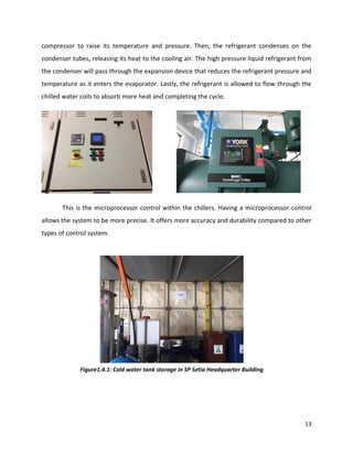
This document provides information about the building services systems in the S P Setia Headquarters building in Selangor, Malaysia. It discusses the HVAC, electrical, vertical transportation, and fire protection systems. The HVAC system uses a jet fan system for mechanical ventilation in the basement parking area. It also has a centralized air conditioning system with packaged air cooled chillers, cooling towers, air handling units, VAV boxes, and underfloor air distribution. The electrical system has high tension, low tension, and generator rooms. The vertical transportation system uses gearless machine roomless lifts. The fire protection consists of passive fire protection elements and an active smoke detection system.

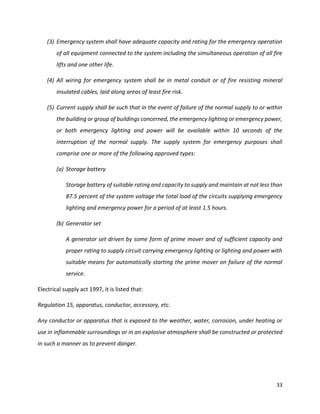
![68
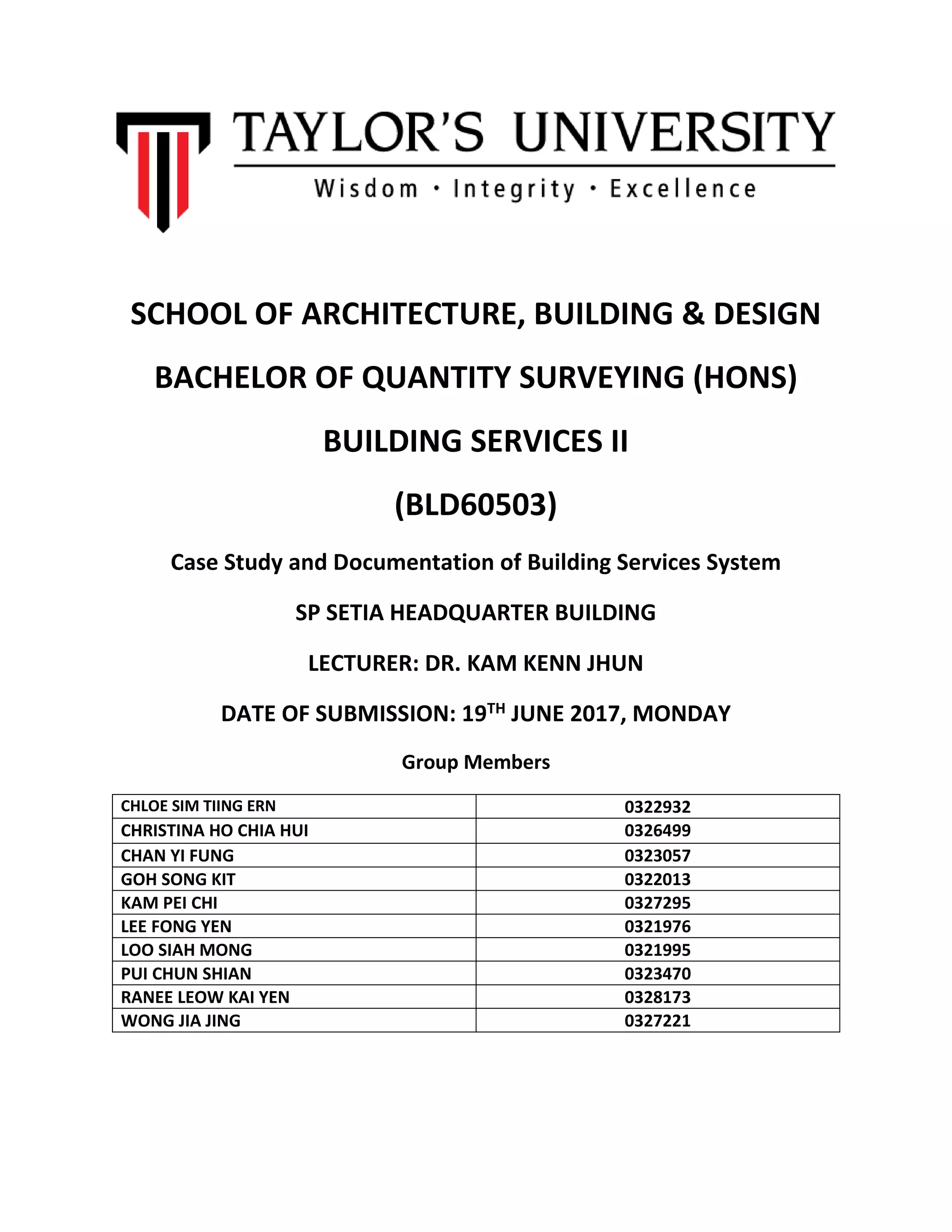
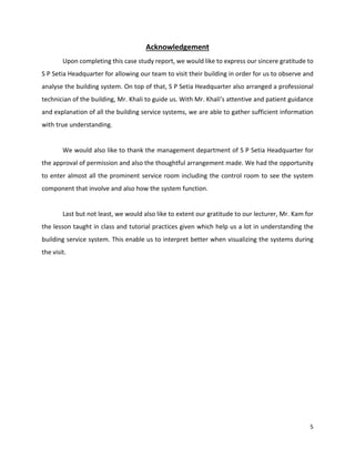
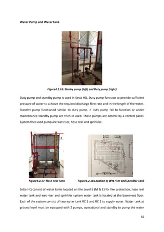
Emergency Exit Signage
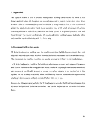
The exit emergency signage is mostly located on top of the fire door. The sign indicates the
way to outdoor area or assembly point. It is an effective guidance tool that helps people
reduce panic and confusion by providing a clear directional system in case of an emergency.
These signs are ever ready when the emergency happen. The letters are written in block
letters which is big and clear enough to be seen easily and are always installed with bright
green lights to attract attention when there is no electricity supply. The emergency exit
signage function opposes the building’s electrical supply. When the main electrical supply has
been cut off, the exit sign will automatically switch on.
Figure 4.1.7: Emergency “KELUAR” [EXIT] Signage
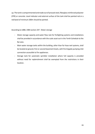
Under UBBL 1984 Section 172 :Emergency Exit [KELUAR] Signs
-A sign “KELUAR” with an arrow indicating the direction shall be placed in every floor where
the direction of the travel to reach the nearest exit is not immediately apparent.
-All exit signs shall be illuminated continuously during periods of occupancy.
-illuminated signs be provided with two electric lamps.](https://image.slidesharecdn.com/building-services-final-copy-to-print-170620090931/85/Building-services-final-copy-to-print-68-320.jpg)
![97
REFERENCES
1. Advantage Air Systems. (2017). The benefits of air conditioning in the workplace. [online]
Available at: http://www.advantage-asl.co.uk/news/the-benefits-of-air-conditioning-in-the-
workplace [Accessed 18 Jun. 2017].
2. Airconditioningwellingborough.co.uk. (2017). Air Conditioning Explained. [online] Available at:
http://www.airconditioningwellingborough.co.uk/Air-Conditioning-Explained.asp [Accessed 18
Jun. 2017].
3. Buildings.com. (2017). The Basics of Passive Fire Protection. [online] Available at:
http://www.buildings.com/article-details/articleid/5851/title/the-basics-of-passive-fire-
protection- [Accessed 18 Jun. 2017].
4. Cbe.berkeley.edu. (2017). Underfloor Technology Overview. [online] Available at:
https://www.cbe.berkeley.edu/underfloorair/techoverview.htm [Accessed 18 Jun. 2017].
5. Centralcityair.com. (2017). Central City Air :: How It Works. [online] Available at:
http://www.centralcityair.com/how-it-works.html [Accessed 18 Jun. 2017].
6. Coolingtechnology.com. (2017). Cooling Technology - Water Cooled Chillers & Air Cooled Chillers.
[online] Available at: http://www.coolingtechnology.com/about_process_cooling/water-
cooled-chiller/ [Accessed 18 Jun. 2017].
7. Coopersfire.com. (2017). Fire Curtains & Fire Barriers | Products | Coopers Fire. [online] Available
at: http://www.coopersfire.com/products/fire-curtains [Accessed 18 Jun. 2017].
8. Designingbuildings.co.uk. (2017). Mechanical ventilation of buildings - Designing Buildings Wiki.
[online] Available at:
https://www.designingbuildings.co.uk/wiki/Mechanical_ventilation_of_buildings [Accessed 18
Jun. 2017].
9. Designingbuildings.co.uk. (2017). Underfloor air distribution UFAD - Designing Buildings Wiki.
[online] Available at:
https://www.designingbuildings.co.uk/wiki/Underfloor_air_distribution_UFAD [Accessed 18
Jun. 2017].
10. Electrical-knowhow.com. (2017). Basic Elevator Components - Part One. [online] Available at:
http://www.electrical-knowhow.com/2012/04/basic-elevator-components-part-one.html
[Accessed 18 Jun. 2017].](https://image.slidesharecdn.com/building-services-final-copy-to-print-170620090931/85/Building-services-final-copy-to-print-97-320.jpg)
![98
11. Electrical-knowhow.com. (2017). Elevator Safety System. [online] Available at:
http://www.electrical-knowhow.com/2012/04/elevator-safety-system.html [Accessed 18 Jun.
2017].
12. Elevator Wiki. (2017). Machine room less elevator. [online] Available at:
http://elevation.wikia.com/wiki/Machine_room_less_elevator [Accessed 18 Jun. 2017].
13. Fire Fighting Equipment Malaysia. (2017). Fireman Intercom System Malaysia | Fire Equipment
& Training. [online] Available at: https://www.firefightingequipment.my/fireman-intercom-
system/ [Accessed 18 Jun. 2017].
14. Firesafe.org.uk. (2017). Fire Doors : Firesafe.org.uk. [online] Available at:
http://www.firesafe.org.uk/fire-doors/ [Accessed 18 Jun. 2017].
15. Firesafe.org.uk. (2017). Passive Fire Protection : Firesafe.org.uk. [online] Available at:
http://www.firesafe.org.uk/passive-fire-protection/ [Accessed 18 Jun. 2017].
16. Firesafe.org.uk. (2017). Fire Alarm Systems : Firesafe.org.uk. [online] Available at:
http://www.firesafe.org.uk/fire-alarms/ [Accessed 18 Jun. 2017].
17. Goodmanmfg.com. (2017). How Central AC Systems Work. [online] Available at:
http://www.goodmanmfg.com/resources/heating-cooling-101/how-central-ac-systems-work
[Accessed 18 Jun. 2017].
18. Hub, S. (2017). What is fire? [online] Science Learning Hub. Available at:
https://www.sciencelearn.org.nz/resources/747-what-is-fire [Accessed 18 Jun. 2017].
19. Iklimnet.com. (2017). Cooling Tower. [online] Available at:
http://www.iklimnet.com/expert_hvac/cooling_tower.html [Accessed 18 Jun. 2017].
20. Quarantelli, E. (2017). Panic Behavior in Fire Situations: Findings and a Model from the English
Language Research Literature. [online] Udspace.udel.edu. Available at:
http://udspace.udel.edu/handle/19716/429 [Accessed 18 Jun. 2017].
21. Science, E. and Science, E. (2017). How Fire Works. [online] HowStuffWorks. Available at:
http://science.howstuffworks.com/environmental/earth/geophysics/fire1.htm [Accessed 18
Jun. 2017].
22. ThoughtCo. (2017). What Is Fire Made Of? Here's the Chemical Composition. [online] Available
at: https://www.thoughtco.com/what-is-fire-made-of-607313 [Accessed 18 Jun. 2017].
23. ThoughtCo. (2017). What is the State of Matter of Fire or Flame?. [online] Available at:
https://www.thoughtco.com/what-state-of-matter-is-fire-604300 [Accessed 18 Jun. 2017].](https://image.slidesharecdn.com/building-services-final-copy-to-print-170620090931/85/Building-services-final-copy-to-print-98-320.jpg)
![99
24. Toshiba-elevator.co.jp. (2017). Machine-Room-less Elevators : Elevators by Operating Principle |
Elevator Basics | TOSHIBA ELEVATOR AND BUILDING SYSTEMS CORPORATION. [online] Available
at: http://www.toshiba-elevator.co.jp/elv/infoeng/elevator_basics/machine/index.html
[Accessed 18 Jun. 2017].
25. Uk.grundfos.com. (2017). Air Handling Unit (AHU) | Grundfos. [online] Available at:
http://uk.grundfos.com/service-support/encyclopedia-search/air-handling-unitahu.html
[Accessed 18 Jun. 2017].](https://image.slidesharecdn.com/building-services-final-copy-to-print-170620090931/85/Building-services-final-copy-to-print-99-320.jpg)


