The document discusses the fire protection systems of Centro Mall in Klang, Malaysia. It provides an overview of active and passive fire protection systems, which work together to control and extinguish fires. The active system includes components like smoke detectors, sprinklers, fire pumps and hydrants that automatically respond to fires. The passive system includes components like fire-rated walls and doors, emergency exits and signage that help contain fires and support evacuation. The case study analyzes how these systems in Centro Mall comply with relevant building codes and ensure fire safety for shoppers.


![A Comprehensive Look at Engineered Smoke Control Systems. (2012, November/December). Retrieved
June 23, 2016, from http://blog.belimo.com/Blog/bid/56533/A-Comprehensive-Look-at-
Engineered-Smoke-Control-Systems
Code Required Testing of Fire, Smoke, and Combination Dampers. (2013, September 30). Retrieved June
23, 2016, from http://blog.belimo.com/Blog/bid/71397/Code-Required-Testing-of-Fire-Smoke-and-
Combination-Dampers
Knapp, J. (2011). Fire Dampers and Smoke Dampers: The Difference is Important[PDF].
Krantz, D. (n.d.). Fire Alarm -- Description. Retrieved June 23, 2016, from
http://www.douglaskrantz.com/BlogStairPressurizationFan.html
Pelonis, S. (2015, November 4). Axial Vs. Centrifugal Fans. Retrieved June 23, 2016, from
http://www.pelonistechnologies.com/blog/axial-vs.-centrifugal-fans
R., & A. (2013, September 12). Info-611: Balanced Ventilation Systems (HRVs and ERVs). Retrieved June
23, 2016, from http://buildingscience.com/documents/information-sheets/info-611-balanced-
ventilation-systems
10 - Stairwell Pressurization - Danfoss. (2015). Retrieved June 23, 2016, from
https://www.youtube.com/watch?v=DvRJLvKTM3c
Liftop Electronic Equipment Co., Ltd - Liftop Escalator Safety Brushes. (2016). Liftop.com. Retrieved 23
June 2016, from http://www.liftop.com/en/perfect_04.asp
How escalator is made - manufacture, making, used, components, structure, steps, industry, machine.
(2016). Madehow.com. Retrieved 23 June 2016, from http://www.madehow.com/Volume-
3/Escalator.html
Escalators - steps, step, tracks, escalator, landing, speed and machines. (2016). Gluedideas.com.
Retrieved 23 June 2016, from http://gluedideas.com/Encyclopedia-Britannica-Volume-8-Part-2-Edward-
EChapter 7 - Fire and Smoke Protection Features. (2016). Publicecodes.cyberregs.com. Retrieved 23 June
2016, from http://publicecodes.cyberregs.com/icod/ibc/2009/icod_ibc_2009_7_par131.htm
xtract/Escalators.html
Chapter 30 - Elevators and Conveying Systems. (2016). Publicecodes.cyberregs.com. Retrieved 23 June
2016, from http://publicecodes.cyberregs.com/icod/ibc/2009f2cc/icod_ibc_2009f2cc_30_sec006.htm
International. (2016). Publicecodes.cyberregs.com. Retrieved 23 June 2016, from
http://publicecodes.cyberregs.com/icod/
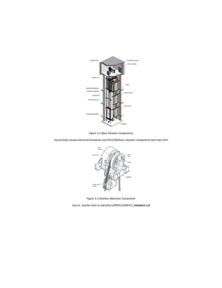
Elevators Types and Classification - Part One. (n.d.). Retrieved June 23, 2016, from
http://www.electrical-knowhow.com/2012/04/elevators-types-and-classification-part.html
Types of Elevators / Classification of Elevators - ELEVATORSTUDY.com. (n.d.). Retrieved June 23, 2016,
from http://www.elevatorstudy.com/2015/11/types-of-elevators-classification-of.html](https://image.slidesharecdn.com/building-service-final-report-160715174451/85/Building-service-final-report-104-320.jpg)
![ABOUT ELEVATORS. (n.d.). Retrieved June 23, 2016, from
http://www.otis.com/site/us/pages/AboutElevators.aspx?menuID=2
Elevators Types and Classification - Part One ~ Electrical Knowhow. (2016). Electrical-knowhow.com.
Retrieved 23 June 2016, from http://www.electrical-knowhow.com/2012/04/elevators-types-and-
classification-part.html
Elevators Types and Classification - Part Two ~ Electrical Knowhow. (2016). Electrical-knowhow.com.
Retrieved 23 June 2016, from http://www.electrical-knowhow.com/2012/04/elevators-types-and-
classification-part_04.html
Elevators Types and Classification - Part One ~ Electrical Knowhow. (2016). Electrical-knowhow.com.
Retrieved 23 June 2016, from http://www.electrical-knowhow.com/2012/04/elevators-types-and-
classification-part.html
Traction Elevators -types of elevators(lifts) - ELEVATORSTUDY.com. (2016). Elevatorstudy.com. Retrieved
23 June 2016, from http://www.elevatorstudy.com/2015/11/traction-elevators-types-of.html
Chapter 30 - Elevators and Conveying Systems. (2016). Publicecodes.cyberregs.com. Retrieved 23 June
2016, from http://publicecodes.cyberregs.com/st/ca/st/b200v10/st_ca_st_b200v10_30_sec006.htm
About ICC | ICC. (2016). Iccsafe.org. Retrieved 23 June 2016, from http://www.iccsafe.org/about-
icc/overview/about-international-code-council/
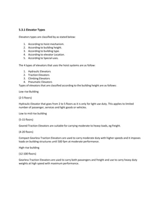
Sigma elevator shaft.JPG. (2016). Elevator Wiki. Retrieved 23 June 2016, from
http://elevation.wikia.com/wiki/File:Sigma_elevator_shaft.JPG
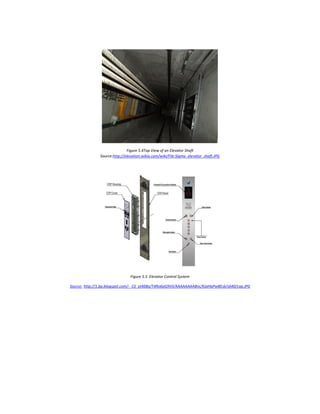
Haq, D. Z. (n.d.). Vertical Transportation: Elevators & Escalators [PDF]. Professor Depatment of
Mechanical Engineeing, Bangladesh University of Engineering & Technology.
ME 415: Refrigeration & Building Mechanical System
Popp, J. (n.d.). Elevator System [PDF]. APPA.
Leadership in Educational Facilities](https://image.slidesharecdn.com/building-service-final-report-160715174451/85/Building-service-final-report-105-320.jpg)


![Building services report [final]](https://cdn.slidesharecdn.com/ss_thumbnails/buildingservicesreportfinal-141209075559-conversion-gate02-thumbnail.jpg?width=640&height=640&fit=bounds)


