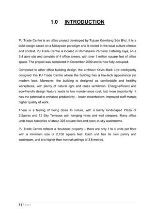
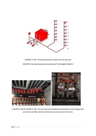
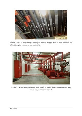
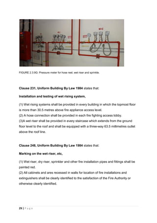
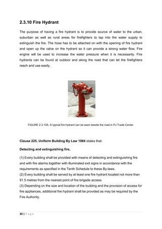
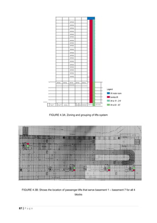
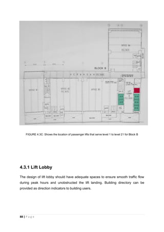
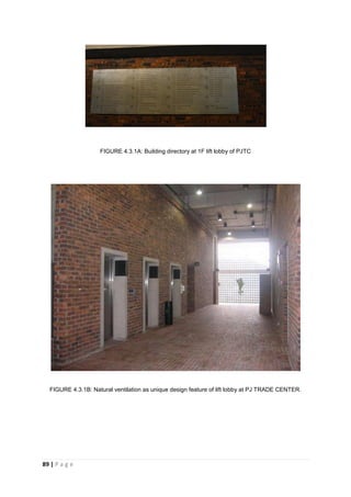
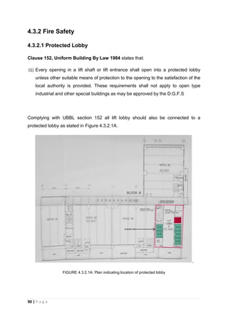
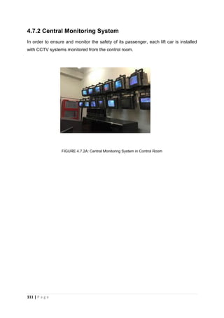
This document provides an overview of the fire protection system used in PJ Trade Centre, a large office building in Petaling Jaya, Malaysia. It discusses both active and passive fire protection elements. For active fire protection, it describes the fire detection, alarm, and suppression systems used, including smoke detectors, manual pull stations, sprinklers, and fire extinguishers. It also discusses the emergency communication and evacuation systems. For passive fire protection, it examines compartmentation, fire resistant staircases, doors, signage, and other building elements designed to contain fires and enable safe evacuation. The document adheres to relevant Uniform Building By-Laws and standards regarding fire protection requirements for large commercial buildings in Malaysia.

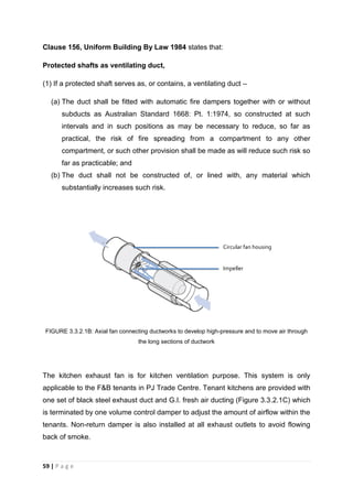
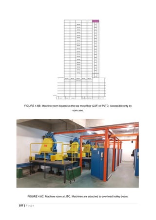
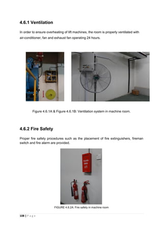
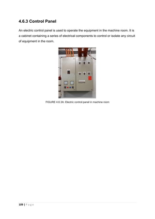
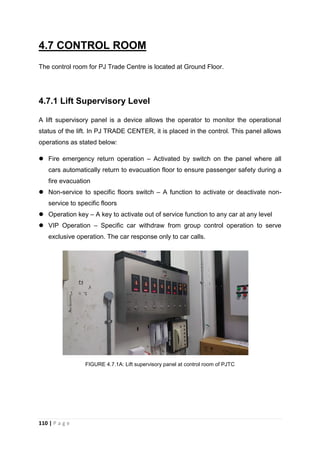


![Building services report [final]](https://cdn.slidesharecdn.com/ss_thumbnails/buildingservicesreportfinal-141209075559-conversion-gate02-thumbnail.jpg?width=640&height=640&fit=bounds)


