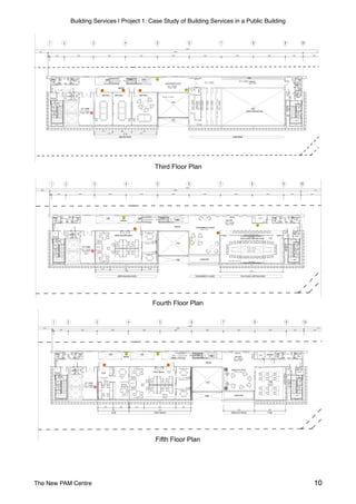
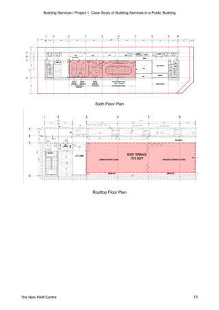
The document provides plans and details for a case study of the building services at the New PAM Centre in Bangsar, Kuala Lumpur. It includes floor plans for 6 levels of the building as well as sections on the methodology, fire protection systems, mechanical ventilation, air conditioning, mechanical transportation, and mechanical parking systems. The case study examines both the active and passive fire safety systems, various mechanical ventilation components, the variable refrigerant flow air conditioning system, elevator systems, and the type of mechanical parking system used in the building.

![Building Services | Project 1: Case Study of Building Services in a Public Building
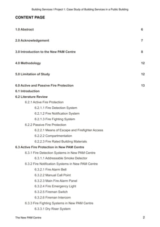
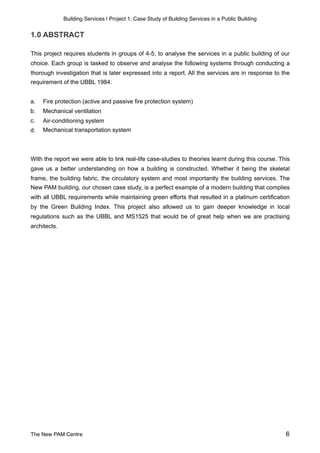
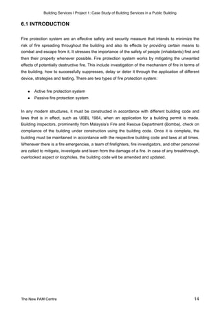
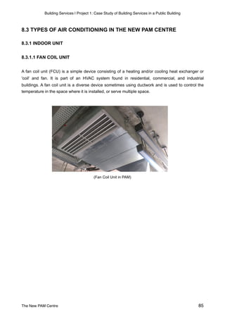
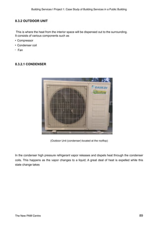
6.3.2.3 MAIN FIRE ALARM PANEL
The main fire alarm panel is located at the lower ground floor of New PAM Centre in the control
room. The main fire alarm control panel process results detected by sensors, control alarm
devices and set off alarms to permanently manned stations and the fire department. They
continuously monitor extinguishing systems for functionality and trigger them electrically if
necessary. In case of danger, it receives signals from the fire alarm bell, detectors and manual call
point as well as monitors and provides notifications to the occupants in the building.
Through the main fire alarm panel, it has access to control HVAC systems, building automation
controllers, access points, and elevators to isolate the fire or route personnel during an emergency.
( [left] Fire Alarm Panel in PAM Centre. [right] Main fire alarm panel in PAM Centre control room. )
The New PAM Centre 27](https://image.slidesharecdn.com/366726664-building-services-pam-centre-171212061541/85/PAM-centre-building-services-27-320.jpg)
![Building Services | Project 1: Case Study of Building Services in a Public Building
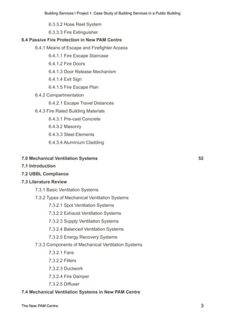
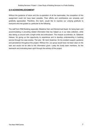
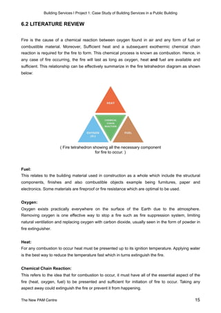
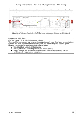
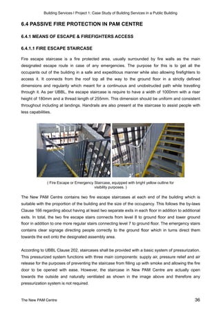
( Fifth floor plan indicating location of firemen switch on every floor )
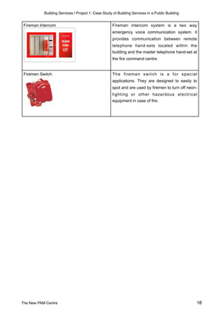
6.3.2.6 FIREMAN INTERCOM
( [Left] Firemen intercom in PAM Centre. [Right] Main firemen intercom system in PAM Centre control room. )
Firemen intercom system provides a two-way communication between the Remote Telephone
Headset(s) located in the building and the Master Telephone Headset located at the fire command
centre. The intercom headsets are located at both stairway of each floor and lift lobbies whereas
the master telephone headset is located at the lower ground floor in the control room of PAM
Centre.
The New PAM Centre 29](https://image.slidesharecdn.com/366726664-building-services-pam-centre-171212061541/85/PAM-centre-building-services-29-320.jpg)
![Building Services | Project 1: Case Study of Building Services in a Public Building
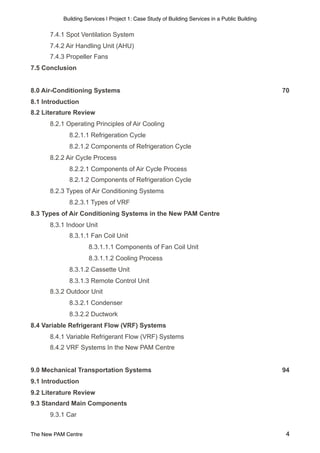
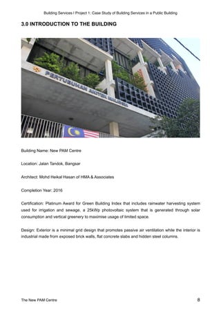
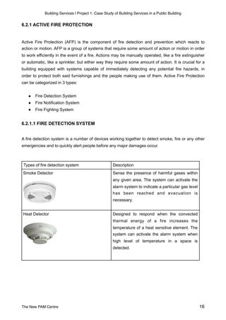
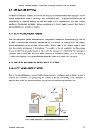
( [Left] Smoke Seal. [Middle] Automatic Door closing mechanism. [Right] Lock mechanism. )
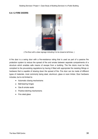
New PAM Centre contains both single swing fire door and double swing fire door. Doors that are
specifically being used in the building is made out of solid hardwood core with assumpted fire-
resistance rating of half hour based on provision given in UBBL Clause 163, Half hour and one
hour doors. Vision panel or small windows is glazed with 6mm Georgian Wire Glass to prevent
hitting or obstructing another person while evacuating. Furthermore, it is equipped with automatic
door closers of the hydraulically spring operated type. This allows the doors to be closed at all
times whenever no one is using it to prevent fire entering the closure.
The New PAM Centre 39](https://image.slidesharecdn.com/366726664-building-services-pam-centre-171212061541/85/PAM-centre-building-services-39-320.jpg)
![Building Services | Project 1: Case Study of Building Services in a Public Building
Book
Uniform building by-laws 1984 : (as at 1st November 2013). (2013). Petaling Jaya: International
Law Book Services.
Lecture Slides
Hassan, S. (2017, September 15). BLD60903: Building Services, week 3: Air-conditioning Systems
[PowerPoint slides]. Retrieved from https://www.facebook.com/download/preview/
322961031509384
Hassan, S. (2017, September 15). BLD60903: Building Services, week 3: Air-conditioning:
Packaged and Plant Systems [PowerPoint slides]. Retrieved from https://www.facebook.com/
download/preview/828826777277610
Hassan, S. (2017, September 29). BLD60903: Building Services, week 5: Fire Protection in
Buildings (Active) [PowerPoint slides]. Retrieved from https://www.facebook.com/download/
preview/1499538896807550
Hassan, S. (2017, October 6). BLD60903: Building Services, week 6: Fire Protection in Buildings
(Part 1) [PowerPoint slides]. Retrieved from https://www.facebook.com/download/preview/
138941643392817
Rabu, A. (2017, September 29). BLD60903: Building Services, week 5: Active Fire Protection
System [PowerPoint slides]. Retrieved from https://www.facebook.com/download/preview/
1825576184180831
Sulaiman, A. (2017, September 2). BLD60903: Building Services, week 2: Mechanical
Transportation [PowerPoint slides]. Retrieved from https://www.facebook.com/download/preview/
214486499086719
Sulaiman, A. (2017, September 22). BLD60903: Building Services, week 4: Mechanical Ventilation
[PowerPoint slides]. Retrieved from https://www.facebook.com/download/preview/
1138758546261026
The New PAM Centre 122](https://image.slidesharecdn.com/366726664-building-services-pam-centre-171212061541/85/PAM-centre-building-services-122-320.jpg)