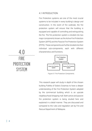
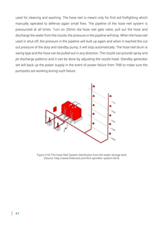
1. B U I L D I N G
S E R V I C E S
( A R C 2 4 2 3 )
CASE STUDY AND DOCUMENTATION OF
BUILDING SERVICES SYSTEMS
TUTOR: AR SATEERAH HASSAN
EDWARD CHENG MUN KIT
0313466
LIM PUI YEE
0313605
NICOLE HOOI YI TIEN
0313611
RICKY WONG YII
0313785
VICKY LEE WEI KEE
0313317
ZHUANG ZHI JIE
0314224
2. CONTENT
1.0 ABSTRACT 1
2.0 ACKNOWLEGEMENT 2
3.0 INTRODUCTION: PUBLIKA 3
4.0 FIRE PROTECTION SYSTEM 4-59
4.1 Introduction
4.2 Literature Review
4.2.1 Fire Safety
4.2.2 Fire Protection and Prevention
4.3 Passive Fire Protection System
4.3.1 Fire Detection System and Alarm Devices
4.3.1.1 Heat Detector
4.3.1.2 Smoke Detector
4.3.1.3 Fire Break Glass Call Point
4.3.1.4 Fire Alarm Bell
4.3.1.5 Fireman Intercom System
4.3.1.6 Fireman’s Switch
4.3.2 Fire Control System
4.3.2.1 Fire Control Room
4.3.2.2 Fire Pump Room
4.3.2.3 Fire Sprinkler System
4.3.2.4 Carbon Dioxide Fire Suppression System
4.3.2.5 Dry Riser System
4.3.2.6 Wet Riser System
4.3.2.7 Hose Reel System
4.3.2.8 Fire Hydrant System
4.3.2.9 Portable Fire Extinguisher
4.4 Passive Fire Protection System
4.4.1 Compartmentalization
4.4.1.1 Fire Roller Shutter
4.4.2 Opening Protection
4.4.2.1 Fire Door
4.4.3 Fire Escape
4.4.4 Emergency Lighting and Signage
4.4.5 Smoke Curtain
3. 4.4.6 Fire Extinguisher
5.0 MECHANICAL VENTILATION SYSTEM 60-73
5.1 Introduction
5.2 Literature Review
5.3 Centralized Mechanical Ventilation System
5.4 Fan Coil Unit
5.5 Types of Fan
5.5.1 Propeller Fan
5.5.2 Axial Fan
5.5.3 Ductwork
5.5.4 Supply Air Diffuser/Grille
5.5.5 Return Air Grille/Fan
5.6 Smoke Extraction System
5.6.1 Fire Damper
6.0 AIR CONDITIONING SYSTEM 74-91
6.1 Introduction
6.2 Literature Review
6.3 District Cooling System
6.4 Chilled Water Air Conditioning System
6.5 Components of Chilled Water Air Conditioning System
6.5.1 Cooling Tower
6.5.1.1 Totally Enclosed Fan Cooled Motors (TEFC)
6.5.1.2 Air inlet louver and screen
6.5.1.3 Valves and pump
6.5.1.4 Condenser water system
6.5.2 Air Handling Unit (AHU)
6.5.2.1 Air filters
6.5.2.2 Cooling air coils
6.5.2.3 Blower/mechanical fan
6.5.3 Water Chiller
6.5.3.1 Evaporator
6.5.3.2 Compressor
6.5.3.3 Condenser
4. 7.0 MECHANICAL TRANSPORTATION SYSTEM 92-115
7.1 Introduction
7.2 Literature Review
7.2.1 Elevator
7.2.2 Escalator
7.2.3 Travelator
7.3 Types and Components of Mechanical System
7.3.1 Elevator
7.3.1.1 Traction Lift
7.3.1.2 Machine Room
7.3.1.3 Hoistway
7.3.1.4 Cable System
7.3.1.5 Suspension Rope & Guide Rails
7.3.1.6 Counterweight
7.3.1.7 Key Control Panel
7.3.1.8 UBBL codes applied by JKR
7.3.2 Escalator
7.3.2.1 Steps & Rail Guide
7.3.2.2 Combplates
7.3.2.3 Railing
7.3.2.4 Electric motor
7.3.2.5 Top and bottom sprocket assembly
7.3.3 Travelator
8.0 CONCLUSION 116
9.0 REFERENCE 117-118
5. 1
This research report will look into the details of the
services present in Publika Solaris Dutamas such as
fire protection system, mechanical transportation,
mechanical ventilation system and air-conditioning
system. Thorough analysis and synthesis on the
components and the functions of these systems in a
building’s operation. A conclusion of these system will
be generated through our understanding of these
services in regards to the Uniform Building-By-Law,
Malaysian Standards requirements as well as other
relevant rules and regulations.
1.0
ABSTRACT
6. 2
First and foremost, we would like to thank Mr Aizam,
the manager of SCM Property Services Sdn Bhd of
Sunrise UEM Group and also Ms Jaisree Bjiakumarin,
the Senior Building Executive of Property Management
who had been kind enough to give us permission to
conduct a site visit and in-depth study on the systems
of Publika and Solaris Dutamas. In addition, we would
like to express our deepest appreciation for providing
us with guidance to complete this report and giving us
much suggestion during our meeting sessions.
Nevertheless, we would also like to thank our tutor, Ar
Sateerah who has been guiding us throughout the
tutorial session and making calls to Publika to get their
approval for this site visit. Last by not least, we would
like to thank each member that has put in much effort
in cooperating with each other and helping one another
in making this project a successful one.
2.0
ACKNOWLEGEMENT
7. 3
Figure 3.1 Publika Solaris Dutamas
Publika Solaris Dutamas located at Sri Hartamas, is an
upscale neighbourhood shopping mall with a variety of
entertainment offerings such as art galleries, boutiques,
stores and merchandise shops as well as restaurants.
The layout of the four-storey Publika is simple and
follows an H-shape with a skylight that lets in plenty of
natural light. And next to the mall are residential
buildings and offices.
Founded by Sunrise Company, Publika was launched in
April 2005 and the entire development was completed
around the end of 2009. Sitting on a 17-acre freehold
site, it comprises 2.14 million square feet of built-up
space that houses over 400 retail outlets, 1,000 office
suites and 800 designer suites. Solaris Dutamas is
famous for its well-integrated living-and-business
development with a promotion of the arts to further
enhance the wellbeing and vitality of all those who live,
work and visit.
3.0
INTRODUCTION
8. 4
4.1 INTRODUCTION
Fire Protection systems are one of the most crucial
systems to be included in every building’s design and
construction. In the event of fire outbreak, the fire
protection system will ensure that the building is
equipped and capable of controlling and extinguishing
the fire. The fire protection system is divided into two
major components known as the Active Fire Protection
System (AFPS) and the Passive Fire Protection System
(PFPS). These components are further divided into their
individual sub-components, each with different
characteristics and functions.
Figure 4.1 Fire Protection Components
This research paper will study in depth of the chosen
building Publika of Solaris Dutamas to have a deeper
understanding of the Fire Protection System adopted
by the commercial building which is an upscale
neighbourhood shopping mall. Both active and passive
fire protection system is being studied here and
explained in a detail manner. They are discussed and
compared to the rules and regulation set by Fire and
Rescue Department of Malaysia.
4.0
FIRE
PROTECTION
SYSTEM
9. 5
4.2 LITERATURE REVIEW
4.2.1 Fire Safety
Fire plays a vital role in our everyday routine. However, is it important to have appropriate
building services and regulations to control Fire because of the release of heat and products
(i.e., smoke, toxic and combustion products) are hazardous to life and properties.
There are two different types of fire protection systems:
(A) Passive Fire Protection (PFP)
Passive Fire Protection is the installation of products or systems which when installed
prevent the passage of hot gasses and flame from passing between fire-isolated
compartments. By creating a fire resistant compartment between rooms and floors, passive
fire protection greatly slows the spread of the fire from the room where it originated. These
products and systems do not require mechanical or electrical activation and once installed
require no maintenance.
(B) Active Fire Protection (AFP)
Unlike passive fire protection, active fire protection systems interact with their surroundings
e.g. by operating fans for smoke extraction, operating a fire sprinkler to control or extinguish
a fire, or opening a vent to allow assisted natural ventilation. Active systems are particularly
useful in larger buildings where it is difficult to ventilate central areas through natural
openings such as windows, smoke and heat extraction systems are often used.
Passive fire protection (PFP) in the form of compartmentalization was developed prior to the
invention of or widespread use of active fire protection (AFP), mainly in the form of automatic
fire sprinkler systems. During this time, PFP was the dominant mode of protection provided
in facility designs. With the widespread installation of fire sprinklers in the past 50 years, the
reliance on PFP as the only approach was reduced.
Lobby groups are typically divided into two camps favoring active or passive fire protection.
Each camp tries to garner more business for itself through its influence in establishing or
changing local and national building and fire codes.
The relatively recent inclusion of performance based or objective based codes, which have a
greater emphasis on life safety than property protection, tend to support Active Fire
10. 6
Protection initiatives, and can lead to the justification for a lesser degree of fire resistant rated
construction. At times it works the other way around, as firewalls that protrude through the
roof structure are used to "sub-divide" buildings such that the separated parts are of smaller
area and contain smaller fire hazards, and do not necessarily require sprinklers.
The decision to favour Active Fire Protection versus Passive Fire Protection in the design of
a new building may be affected by the lifecycle costs. Lifecycle costs can be shifted from
capital to operational budgets and vice versa.
Figure 4.2 Fire Triangle
Four things must be present at the same time in order to produce fire:
Fuel or combustible material
Enough oxygen to sustain combustion
The chemical, exothermic reaction that is fire
Enough heat to raise the material to its ignition temperature
Fuel, oxygen and heat referred to the Fire Triangle. Further clarifies the definition of
combustion by adding a fourth component which is chemical chain reaction, depicting the
concept of the rapid, self-sustaining oxidation reaction. The Fire Tetrahedron depicts the
growth of ignition into fire. Therefore, by removing on these components above, fire will
extinguish. Essentially, fire extinguishers put out fire by removing one or more components
of Fire Triangle or Fire Tetrahedron.
Figure 4.2: Fire Tetrahedron
11. 7
4.2.2 Fire Protection and Prevention
Fire protection include
Fire alarm devices
Fixed firefighting equipment
Having a permanent water supply
Include portable firefighting equipment
Fire prevention include
Include storage
Ignition hazards
Open yard storage
Temporary building
12. 8
4.3 ACTIVE FIRE PROTECTION SYSTEM
The active Fire Protection (AFP) is a very important and integral part of any fire safety strategy
which is activated either mechanically or electronically during the event of a fire outbreak.
The AFP basically consists of the manual or automatic fire fighting system installed in a
building with the function to give warning in the case of a fire. The AFP System is further
divided into different categories; fire detection, smoke and heat extraction system, fire
suppression and sprinkler system. Below are further explanations on the active systems
found in Publika, Solaris Dutamas:
4.3.1 Fire Detection System and Alarm Devices
Fire Detection systems are critical components in a basic building as they are designed to
provide warning of a fire outbreak before the situation worsens, hence allowing the
appropriate firefighting actions to take place. There are specially two ways as to how a fire
detection system works; automatically or manually. Detectors such as the smoke and heat
detectors carry out the automatic activation whilst the manual activation is by breaking the
glass at the call point unit or fire alarm pull station. The primary objective of a fire detection
system is to alert the users of the building through audio and visual means. After a fire has
been detected, this will activate the fire suppression and control system so that firefighting
actions will be carried out.
13. 9
4.3.1.1 Heat Detector
Figure 4.3 Heat Detector located in Publika, Solaris Dutamas
Figure 4.4 EST International Heat Detector
(Source: http://www.edintel.com/pdf/siga-hrs.pdf)
UBBL – SECTION 225. (1)
Every building shall be provided with means of detecting and extinguisher fire and alarms
together with illuminated exit signs in accordance with the requirements as specified in the
Tenth Schedule to these By-Laws
Heat detector function best in fires that involve high flames, intense heat and little initial
smoke. The Heat detector above is conventional I type heat detector that considered as a
fixed temperature unit type. The heat detector composed of a heat sensitive eutectic alloy
that will reach the eutectic pint changing state from a solid to a liquid during fire. When the
ambient temperature increases sufficiently to predetermined level where the heat detector
will operate. For most fixed temperature heat detector, when the surrounding temperature
14. 10
reaches 58 degree Celsius. Thus, it is encouraged to install heat detectors in areas that pose
a higher likelihood of high flames and intense heat. The heat detectors are intelligent
Addressable Heat Detectors by EST.
Spacing of heat detectors
Spot type heat detector spacing ratings are based on detector installation on a flat, smooth
ceiling that is 3m high. The listed spacing equates detector operation with the opening of a
standard sprinkler head within 2 minutes (+/- 10 seconds) located 3 m from the same fire.
Spot type detector spacing is shown in the figure below. Detector coverage is typically
represented as a square because most structures have flat sidewalls. Actual detector
coverage is a circle whose radius is 0.7 times the listed spacing. Since all of the area within
the detector’s circle of coverage is suitable for detecting a fire, the shape and dimensions of
the detector coverage square in the figure below may be modified.
Figure 4.5 Heat Detector Spacing
(Source: https://www.edwards-signals.com)
15. 11
When installed on the ceiling, spot type heat detectors must be located a minimum of 10 cm
from side walls. When installed on side walls, the detector must be between 10 cm and 30
cm from the ceiling, as shown below.
Figure 4.6 Heat Detector Placement
(Source: https://www.edwards-signals.com)
16. 12
4.3.1.2 Smoke Detector
Figure 4.7 Smoke Detector Placement in Publika
Figure 4.8 EST International Smoke Detector
(Source: http://www.edintel.com/pdf/siga-hrs.pdf)
UBBL-SECTION 225 (1)
Every building shall be provided with means of detecting and extinguisher fire and alarms
together with illuminated exit signs in accordance with the requirements as specified in the
Tenth Schedule to these By Laws
Smoke detectors sense the presence of smoke particles. In order for a smoke detector to
sense these particles, smoke must travel from the point of origin to the detector. When
evaluating a particular building or location for detector layout, likely fire locations should first
be determined, and paths of smoke travel from each of these fire locations should be
determined. Wherever practical, actual field tests should be conducted. The most desired
location for smoke detectors would be the common points of intersection of smoke travel
17. 13
from fire locations throughout the building. Ceiling height, construction, and ventilation play
significant roles in smoke detector performance. When a fire occurs in the building, the first
procedure to be taken place in the active fire system is the smoke detector positioned on the
ceiling on every floor. To protect the whole floor area, a few smoke detectors placed
everywhere around the particular floor in every level to detect the presence of smoke. The
closest smoke detector within where the fire is taken place will detect the smoke and then
automatically signals the fire alarm control panel located in the control room. In the Publika,
the smoke detector used are of the EST brand or Edwards Systems Technology describes as
Intelligent Addressable Photoelectric Smoke Detectors which gathers analog information
from its smoke sensing element and concerts it into digital signals (Edward Systems
Technology International, 2012)
Spacing of smoke detector
The spot type smoke detector spacing recommendation of 9.1 m is based upon the detector
installation on a smooth ceiling that is 3 m high. Detector coverage is typically represented
as a square, because most structures have flat sidewalls. Like spot type heat a detector,
smoke detector coverage is a circle whose radius is 0.7 times the listed spacing. Since all of
the area within the detector’s circle of coverage is suitable for detecting smoke from fire, the
shape and dimensions of the detector coverage square may be modified.
Figure 4.9 Smoke Detector Spacing
(Source: https://www.edwards-signals.com)
18. 14
Under floor installations
When spot type smoke detectors are installed under raised floors, they are subjected to high
air velocities and dust levels. Detectors should be installed base up or base vertical (never
down) as shown in the figure below. This minimizes the effects of dirt, dust, and mechanical
interference from cabling.
Figure 4.10 Permissible smoke detector under floor mounting
(Source: https://www.edwards-signals.com)
Figure 4.11 Smoke Detector located in Publika Level 4-6
19. 15
4.3.1.3 Fire Break Glass Call Point
The fire Break Glass Call Point is a manually actuated device which has to be activated by the
occupants of the building. In every building, the call point should be placed strategically and
visible to all the users so that it would be much easier to activate in the event of a fire. Call
points are used to initiate an alarm signal and operate by means of simple button press.
Connected to a central alarm system in the building, they are usually linked to a local fire
bridge dispatcher as well. To activate via the call point, occupants are just required to break
the glass and this will triggers the alarm system. It is very easy to break as the glass is a very
fragile element. The call points used in Publika is of the DEMCO brand as well.
Figure 4.12 The Fire Break Glass Call Point
located in Publika
Figure 4.13 Diagram of the DEMCO Break Glass Call Point
specifications
(Source:
http://www.demcoalarm.com/products_call_point_d128.h
tml)
20. 16
As mentioned earlier, the fire break glass call points require careful placing and positioning.
Below are some guidelines on the correct placement in accordance to the Fire Action LTD
(2014):
1. It should be placed on the exit routes and in particular on the floor landings of staircase
and at all exits to the open air.
2. It should also be located so that no person needs to travel more than 45m from any
position within the premises in order to give an alarm (30m if layout is unknown).
3. Call points should usually be fixed at a height of 1.4m above the floor, at easily
accessible, well-illuminated and conspicuous position free from obstruction.
4. The method of operation of call points in an installation should be identical unless
there is a special reason for differentiation.
Figure 4.14 Fire Break Glass Located in Publika at Level 4-6
21. 17
4.3.1.4 Fire Alarm Bell
UBBL-Section 237
Alarm Bell must provide a minimum sound level of 65db (A) pr +5db (A) above any
background noises, which is likely to persist for more than 30 seconds.
Fire alarm bells are important components in the Fire Detection system as the sounds
generated are usually the first warnings that make users aware of the fire threats in the
building. The fire alarm bells are activated by the fire detectors. Publika’s alarm bells are
DEMCO branded. Designed professionally to meet the needs of firefighting and the detection
systems with central control equipment, the simplicity of the design incorporates fewer
working parts, thus encourage easy installation and high level of efficiency capable in
operating under the most adverse conditions (DEMCO INDUSTRIAL SDN BHD,n.d).
Figure 4.17 Fire Alarm Bell Located in Publika at Level 4-6
Figure 4.15 A DEMCO Fire Alarm Bell found
in Publika
Figure 4.16 Specifications of a DEMCO bell
according to universal regulations
(Source:
http://www.demcoalarm.com/products.html)
22. 18
4.3.1.5 Fireman Intercom System
The fireman Intercom System provided a reliable two-way emergency voice communication
system between the Master Console handset at Fire Command Centre and the remote
handset stations which is located around the building. This system comprised of the remote
Handset Station and the Master Control Panel. The master control panel comprises of a
Master handset, as System Control Module and Zone Control Modules. During a fire break
out, a call alert lamp will flash with audible signals at the master control panel whenever there
is an incoming call. As the handset is lifted to answer the incoming call, the audible signal will
be silenced. The master control panel is also equipped with a fault indicator unit which
enables an easier identification of the fault at hand. The master control console is located in
the Fire Control Room of Publika.
Figure 4.18 Remote Handset Station
Figure 4.19 Master Control Panel located in the Fire
Control Room
Figure 4.20 Master Control Panel located in the Fire
Control Room
23. 19
4.3.1.6 Fireman’s Switch
A Fireman Switch functions to switch off or isolate the power supply of certain power
systems in the building. This switch is only operable by a fireman during an emergency
situation. The fireman switch is located in every level of a building and is categorized into a
few switches depending on the type of electrical supply to be switched off. To be specific, it
is mostly used by the firemen to turn off neon lighting or hazardous electrical equipment in
the case of a fire breakout. It can also be used to run the under voltage release or shunt trip
in the main incoming breaker. If there is a fire in the building, the fireman uses an insulated
rod to pull the handle which isolates the utility supply to the building (ABB, 2012). In Publika,
the Fireman Switches are mostly found in the emergency staircase areas so that it is easily
visible for immediate action.
Figure 4.21 Fireman’s Switch located in the emergency staircase
24. 20
4.3.2 Fire Control System
4.3.2.1 Fire Control Room
UBBL-SECTION 238
Every large premises or building exceeding 30.5 meters in height shall be provided with a
command and control center located on the designated floor and shall contain a panel to
monitor the public address, fire brigade communication, sprinkler, water flow detectors, fire
detection and alarm systems and a direct telephone connection to the appropriate fire-
station by passing the switch board.
The fire control Room plays a very important role in a building. It could be described as the
centre or heart of the building as this room houses all the control for the building’s fire
protection system, fire pumps, secondary water supply, air handling systems, stairwell door
controls, communication system and the elevator control. The key cabinet which has access
to all keys in the building is also located in the fire control room. This is to make it easier for
the fire fighters to move around if an emergency were to occur. The fire control room is
Publika is located at Basement 1.
Figure 4.22 Fire Control Room Entrance located at Basement of Publika
25. 21
According to Consumes Fire Department (2014), the exterior access door should be full sized
and clearly marked “Fire Control Room” with a minimum of 3 letters contrasted in colour from
the background.
1. Have a minimum floor area of 10 meters square and may be larger depending on the
required equipment.
2. Preferable adjacent to a lift lobby or any other location as designated by the relevant
authority.
3. Be accessible via 2 travel oaths. One from the front entrance and the other from a
public place for a fire isolated passageway, which leads to a public space and has a
two hour fire rated door.
4. Have an independent air handling system if mechanical ventilation is provided
throughout the whole building.
5. Be adequately illuminated to not less than 400 lux.
6. Provide the ease of communication (through telephones and loudspeakers) with all
parts of the building, and with other fire emergency services.
7. Be provided with insulation from ambient building noise.
8. Be under control of the Chief Fire Warden or a similarly appointed person.
Figure 4.23 Manual Control Panel will all
the fire detectors and location layout
Figure 4.24 Manual Control Panel will all
the fire detectors and location layout
26. 22
Any fire control room must contain the following details:
1. Automatic fire alarm and sprinkler indicator boards with facilities for sounding and
switching off alarms and visual status indication for all relevant pumps, smoke control
fans, air handling systems, generator and other required fire safety equipment
installed in the building depending on the circumstances and system present in a
building.
2. A telephone directly connected to an external exchange.
3. The control Console of the emergency warning and Intercommunication system.
4. A blackboard or whiteboard not less than 1200mm.
5. A pin board not less than 1200mm wide x 1000mm high.
6. A raked plan layout table of a size suitable for laying out the building plan.
7. A repeater panel of the lifts position indicator board.
8. A switch to isolate background music when required.
9. Remote switching controls for gas or electrical supplies.
10. Building security, surveillance and management systems if they are completely
segregated from all other plans.
Figure 4.25 Master handset panel Figure 4.26 CCTV monitors in the Fire
Control Room
27. 23
4.3.2.2 Fire Pump Room
The fire pump room plays a crucial part in order for a fire fighting system to actually work
during a fire breakout. The fire pump room houses all the pump systems and water storage
tanks. The main systems that function through the fire pump are the sprinkler and hose reel
system. The fire pumps can be powered by diesel, electronic or steam.
Figure 4.27 Fire Fighting Pump Room Entrance located at Basement of Publika
Figure 4.28 The Fire Pump Room with its pumps
28. 24
(a) Pumps
Pumps are required in order to provide adequate supply of water to each riser at all times. All
the pumps are connected in parallel, with their suctions permanently “wet” when the tank is
filled. There are three main pumps known as the Jockey Pump, Duty Pump and Standby
Pump.
The Jockey Pump is an apparatus that works alongside a fire pump as an apart of the fire
protection system. It function to maintain the pressure in the sprinkler piping system. It also
assists in the prevention of drainage when a fire breaks out and water starts rushing into the
pipes. Jockey pumps are only used for the sprinkler system. If a fire sprinkler is activated, a
pressure drop will be sensed by the fire pimp’s automatic controller, which stimulates the fire
pump to start working.
The Duty Pump functions when the pressure in the pipe goes down to 35 PSI, and supplies
enough pressure of water in order to maintain the system and make sure it is running well.
However, if the duty pump encounters any form of problems which prevents its proper
operation or goes down to 25 PSI the standby pump will automatically be activated from the
master control panel if required.
The Standby Pump shares the exact function as the duty pump. As mentioned above, it
replace the duty pump when it is not functioning or needs to be switched off manually.
Figure 4.29 Jockey Pump Figure 4.30: Standby Pump Figure 4.31 Duty Pump
29. 25
The readings on the pressure switches for the 3 pimps to cut in and out:
Figure 4.32 Readings of pressure switches for the 3 pumps
Figure 4.33 Readings of pressure switches for the 3 pumps
30. 26
(b) Water Storage Tank
The Water Storage for the sprinkler system and the hose reel system is located in the
basement. The water storage tank used in Publika is molded in a sturdy steel formwork to
store fire-fighting water for sprinkler system and hose reel system. The quantity of water plus
the amount required in order to satisfy daily peak demands is available in the fire water
storage tank.
Figure 4.34 Water Storage Tank
Figure 4.35 Location of Pump Room at Basement of Publika
31. 27
4.3.2.3 Fire Sprinkler System
UBBL-SECTION 225. (2)
Sprinkler valves shall be located in a safe and enclosed position on the exterior wall
and shall be readily accessible to the Fire Authority.
All sprinkler systems shall be electricity connected to the nearest fire station to provide
immediate and automatic relay of the alarm when activated.
The sprinkler installation is designed to operate automatically in the event or a fire. When a
fire occurs, hear rising from the fire is absorbed by a silicone based liquid contained inside
the glass bulb of the nearest sprinkler head. This causes an air bubble inside the glass bulb
to expand. When the temperature surrounding the sprinkler risers above the rated
temperature of the sprinkler head, the glass bulb breaks and ruptures the seal between the
sprinkler head orifice and the system pipe work. This allows water from the sprinkler system
to discharge through the sprinkler head in a predetermined pattern. In the case of the solder
strut type of sprinkler, the glass bulb is replaced by a strut made of metal with a low melting
point. When the strut melts in a fire, the sprinkler releases water extinguisher the fire. Each
Sprinkler head is designed to operate individually, so in the event of a fire, only the sprinkler
heads nearest the fire will be activated. Without the introduction of an accelerated fire, four
sprinkler heads or less would normally activate in a fire. When a sprinkler head is activated,
the flow of water through the sprinkle supply pipe work will be registered b the flow switch on
the local sprinkler floor control valve. The activate flow switch will send a signal to the fire
alarm panel which will then send a visual and audible signal to the fire affected area and to
the fire brigade. As water flow through the sprinkler system, due to the activation of a sprinkler
head, the water pressure in the system falls. When this pressure falls below 90% of the
standing pressure, the sprinkler jockey pump will start. If the system pressure continues to
fall and falls below 80% of the standing pressure, the duty sprinkler pump will start
automatically and the jockey pump start automatically. Once started, both the duty and
standby sprinkler pumps must be stopped manually at the pump controller. When the fire
has been extinguished beyond all doubt, the following procedure should be carried out under
the control of the fire officer in charge:
32. 28
1. Close the isolation or butterfly valve on the relevant sprinkler floor control valve
2. Manually
3. Replace activated sprinkler heads
4. Open the isolation or butterfly valve on the sprinkler floor control valve.
Figure 4.36 The Sprinkler System distribution from the water storage tank and is pumped by the 3 pumps up
to the sprinkler valves
(Source: http://www.fireknock.com/fire-sprinkler-system.html)
Publika is protected throughout by an automatic sprinkler system. The sprinkler system is
the wet pipe system which considered as one of the most common ones implemented in
today’s building. This system is hydraulically designed to provide a water spray density in
accordance with the following schedule, which is based on LPC requirements. The sprinkler
system for Publika is tapped off from existing sprinkler pipe line by others. The sprinkler
system is connected to the pump system consisting of the Jockey, Duty and Standby pump
mentioned in the previous sub-topic. Every floor of the building is provided with one number
of flow switch and one number of isolation valve c/w micro switch. The flow switch and
isolation valve are installed just outside the main tee off from the main distribution pipe for
their respective floor and it has been marked, via a sign board for easy recognition for
maintenance purpose.
33. 29
Advantages of using wet pipe system in accordance to VFP (2014):
1. System us simple and reliable. This system has the least number of components thus
it has the lowest number of items to experience malfunctions.
2. Relative low installation and maintenance expense. Wet pipe sprinkler system requires
the least amount of time for installation due to their overall simplicity. Maintenance
cost savings are also realized since less service time is required in comparison to
others systems.
3. Ease of modification. This system is advantageous since the modification involve
shutting down the water supply, draining pipes and making alterations. Following the
work, the system is pressure tested and restored.
4. Short term down time following a fire breakout. Wet pipe sprinkler system requires the
least amount of effort to restore. Sprinkler protection is reinstated by replacing the
fused sprinklers and turning the water supply back on.
Figure 4.37 Diagram showing the components of a typical Wet Pipe System
(Source: http://www.incontrolfp.com/systems/)
The sprinkler water outlet in Publika are located at ceiling level and a good distance of about
2.5 meters is in between. The sprinkler itself is the spray nozzle which will distribute water
over a defined fire hazard area. The components of a sprinkler include frame, thermal
operated linkage, cap, orifice and deflector (NEDCC, 2014)
34. 30
Figure 4.38 The components of a sprinkler head
(Source: http://www.sarian.ir/Sprinkler-Head-Components.htm)
Below are the function of the specific components:
1. Frame – The frame provides the main structural component which holds the sprinkler
together. Water supply piping is connected to the sprinkler at the base of the frame
which holds the thermal linkage and cap in place and supports the deflector during
discharge. Frame styles include standard and low profile, flush and concealed mount.
Special coatings are also available for areas subject to high corrosive effect.
2. Thermal Linkage – Thermal linkage is a component that controls water release. The
linkage holds the cap in place and prevents the water flow under normal conditions. If
the link is exposed to heat, it will weaken and release the cap. Common linkage styles
include soldered metal levers, frangible glass bulbs and solder pellets. Each link style
is equally dependable.
3. Cap – The cap provides the water tight seal. It is held in place by the thermal linkage,
and falls from position after linkage heating to permit the flow of water. Caps are
constructed solely of metal or a metal with a Teflon disk.
4. Deflector – Its purpose is to break up the water stream discharging from the orifice
into a more efficient extinguishing pattern. Deflector styles determine the way the
sprinkler is mounted, with common mounting styles known as upright, pendent, and
sidewall sprinklers which discharge water in a lateral position from a wall. The
sprinkler requires proper mounting as it is designed to ensure proper action.
35. 31
The Upright sprinkler stands above a pipeline connected to it and its head is projected
upwards. It is widely found in mechanical rooms and other inaccessible areas to provide
better coverage between obstructions. It also has a water deflector on the top so that the
water coming out of the orifice shoots upward spread in a circular pattern like a pattern
sprinkler.
The recessed pendent sprinklers head hangs down from the ceiling connected to the pipe
which is hidden beneath the ceiling. Its water deflector is placed at the bottom and its spreads
water in a circular pattern. Recessed pendent sprinklers have a higher water flow speed than
the upright sprinkler as the radial water pattern flow between the sprinkler orifice and
deflector in comparison to the upright sprinkler which is between the orifice and somewhat
above the deflector.
Figure 4.39 Upright Sprinkler head found in the car park
area
Figure 4.40 Upright Sprinkler Head Diagram
(Source: http://www.incontrolfp.com/systems/)
Figure 4.41 The Recessed Pendent
Sprinkler head found in ground floor
Figure 4.42 The Recessed Pendent
Sprinkler head found in ground floor
Figure 4.43 Recessed
Pendent Sprinkler Head
Diagram
(Source:
http://www.incontrolfp.com
/systems/)
37. 33
4.3.2.4 Carbon Dioxide Fire Suppression System (Co2
)
Figure 4.45 Co2
Fire Suppression System installed in LV room for fire extinguisher
Carbon dioxide in fire protection term, gases that protects electrical equipment from being
burnt such as it sectors, transformers and switchgears. Carbon dioxide is an effective fire
suppression agent applicable to a wide range of fire hazards. Carbon dioxide works quickly,
with no residual clean-up associated with a system discharge which translates into minimal
business interruption. Heat or smoke detectors will detect the heat and sound the alarm and
Co2 gas will flood to the room for high pressure storage cylinders. The gasses are sent via
pipes to the ceiling and under flood distributors. Carbon dioxide is lethal to a person’s health
so occupants must evacuate swiftly in a limited amount of time. The cylindrical tank are
stored in the corner of rooms. Once detected by the heat triggers, the Co2 released, curtain
walls go down and when doors are shut, two indicators will show when the gas operation is
over. Red means gases are still present and green means it is already clear and safe to go in.
Figure 4.46 High Pressure Co2
System Arrangement
(Source: http://www.usbr.gov/power/data/fist/fist5_12/5-12.pdf)
38. 34
High-pressure systems came equipped with “squibs” that explosively ruptured discs to
release gas from the pilot cylinders. High-pressure gas released into the header from the pilot
cylinders caused discs on the slave cylinders to rupture to discharge the remaining gas. This
process was used for both the initial and delayed portions of the CO2 system. In recent years,
squibs have become obsolete, since they are no longer manufactured. Squibs are being
replaced by pneumatic/electrical discharge devices that perform the function of discharging
the pilot cylinders, after which operation of the system is the same as before. For this
modification, equipment that typically needs to be replaced are the fire control panel, pilot
and pressure operated cylinder discharge heads and valves, selector valve, and various
connection components. High-pressure systems require that the content of the CO2 in the
cylinders be verified every 6 months to ensure availability of sufficient CO2. CO2 cylinders
must also be hydrostatically tested every 12 years. High-pressure cylinders must also be
replaced or refilled after a discharge, a time-consuming, labor-intensive, and potentially risky
chore. In order to eliminate the numerous high-pressure cylinders and associated
maintenance tasks, high-pressure systems on large generating units are being converted to
low-pressure systems in some cases, depending on design and cost considerations.
Figure 4.47 Co2
Control System Overview
Source: http://www.usbr.gov/power/data/fist/fist5_12/5-12.pdf
39. 35
Figure 4.48 Location of Co2 Fire Suppression System at Basement of Publika
4.3.2.5 Dry Riser System
UBBL-SECTION 230
Dry riser system shall be provided in every building in which the topmost floor is
more than 18.3 meters but less than 30.5 meters above fire appliance access level.
A hose connection shall be provided in each firefighting access lobby.
Dry shall be of minimum “class c” pipes with fittings and connections of sufficient
strength to withstand 21 bars water pressure.
Dry risers shall be tested hydrostatically not less than 14 bars of pressure for two
hours in the presence of the Fire Authority before acceptance.
All horizontal runs of the rising systems shall be pitched at the rate of 6.35
millimetres in 3.05 meters.
The dry riser shall be not less than 102 millimetres in a diameter in building in which
the highest outlets is 22.875 meters or less above the fire brigade pumping inlet.
102 millimetres diameter dry risers shall be equipped with a two-way pumping inlet
and 152.4
The dry riser system comprises of a vertical pipe with the functions of distributing water to
multiple levels of a building. It plays a very important role in the fire suppression system. Dry
risers are normally installed in fire escape staircases with an Infill (Breeching Valve) at the
building’s ground floor and Landing Valves which usually located on every floor (JP Fire
Protection System Ltd, 2009). When a fire is caught in a building. Dry risers are somewhat a
form of internal hydrants which is used by the fireman in a fire outbreak. Usually dry, they
depend on the fire engines to pump water into the system.
40. 36
Figure 4.49 Dry Riser Inlet found in
Ground Floor, Publika
Figure 4.50 Typical Installation of the Dry Riser
(Source: http://www.alfiresystems.co.uk/dryRiser_how.aspx)
41. 37
4.3.2.6 Wet Riser System
UBBL-SECTION 231
Wet rising system shall be provided in every building in which the top most floor is more than
30.5 meters above the fire appliance access level.
This system is comprised a series of manually operated landing valves located at each floor
in the building. These landing valves are supply with water from water storage tanks (directly
feed from water main) via a pumpsets. Water from the storage is pumped to the landing
valves via a series of riser mains. This system provides a readily accessible source of water
in sufficient quantities and at a pressure which allows the fire brigade to efficiently fight a fire
on any floor or area in the building.
Wet Riser System Layout
The wet riser pump set are consists of 3 pumps. One of is arrange for duty operation, second
is for standby operation and third a much smaller flow rate and is known as a Jockey Pump.
Each pumpsets are connected via pipe manifolds. The duty and standby pumps are designed
to operate when the landing valve has been operated. The jockey pump will run, in the event
of small leaks in the pipe network or a small pressure drop in the system, the jockey pump
will operate to increase the pressure to the correct operating pressure. This will prevent the
duty and standby pumps from activated. Each wet riser pumpsets is connected to a 25mm
diameter pressure sensing pipe. These pressure sensing pipes are connected to pressure
switch. Pump operation is dependent on the pressure switch which are used to start (cut in)
and stop (cut out) the pumps to maintain the required water pressure. Standby generator set
will back-up the power supply in the event of power failure from TNB to make sure the
pumpsets are working during such failure. Each pump starter has manual and automatic
modes of operation to allow testing of the pump to be carried out. Pump starter panel have
externally mounted indicators for phase indication, AC Fail, Start, Stop, Run, AC On. The pump
starter panel is configured to provide duty, standby and jockey pump control in a manner
which prevents the possibility of three pumps running at the same time. A timer relay is also
installed at jockey pump controller. This timer keeps the jockey pump running for a
predetermined minimum time after each automatic start to prevent the pump from starting
and stopping too frequently. The motorized valve is used for the incoming supply to wet riser
42. 38
tank. The functioning of motorized valve is to control the incoming supply water to wet riser
tank. When the Jockey, Duty or Standby pump is running, automatically the motorized valve
is open and the Jockey, Duty or Standby pump is stop, automatically the motorized valve is
closed. Each pump starter panel has manual and automatic modes of operation to allow
testing of the pump to be carried out. Pump starter panel have externally mounted indicators
for phase indicator, AC Fail, Start, Stop, AC On. The pump starter panel is configured to
provide duty, standby and jockey pump control in a manner which prevents the possibility of
three pumps running at the same time. A timer relay is also installed at jockey pump
controller. This timer keeps the jockey pump running for a predetermined minimum after
exam automatic start to prevent the pump from starting and stopping too frequently. The
pumpsets pressure settings have been label at of the respective pressure switch to indicate
the cut in and cut out pressure. A 65mm diameter landing valve is connected to 150 mm
diameter wet riser supply pipes at each floor level. Each landing valves is complete with a
quick coupling adapter, which is compatible with the fire brigades standard hose connection.
These quick coupling connections are screwed directly onto the discharge outlet of the
landing valve. A removable plug secured by a chain is fitted t each landing valve. A 30 meter
of 65mm diameter rubber lined canvas hose is provided at each landing valve. These hoses
are stored on a hose cradle adjacent to each landing valve. Each canvas hose is completer
with a diffuser nozzle.
Figure 4.51 Wet Riser Pipe located at basement of Publika
43. 39
Figure 4.52 The Wet Riser System distribution from the water storage tank
(Source: http://www.fireknock.com/fire-sprinkler-system.html)
Figure 4.53 Location of Wet Riser Pipe at Basement of Publika
44. 40
4.3.2.7 Hose Reel System
UBBL-SECTION 231
A hose connection shall be provided in each firefighting access lobby.
The Hose Reel system is designed to provide the first manual of defense against fires and is
designed for use against small fires. The pipeline of the hose reel system is pressurized at all
times. Turn on the 1 diameter hose reel gate valve, pull out the hose and discharge water
from the nozzle, the pressure in the pipeline will drop. The hose reel system can easily be
operated by one person and required minimum operator instruction. It is however,
recommended that some instruction on the operation of fire hoses be provided for at least
some occupants on each flow of the building.
Hose reel system consists of two pumps. One is arrange for duty operation, second is for
standby operation. Each hose reel drum was equipped with 25mm diameter x 30 meter
rubber hose c/w Jet and Spray nozzle. A ball valve is installing before each of hose reel drum
for easy maintenance. The valve must be kept in close position at all time. An adjustable
nozzle is fitted to each hose. The nozzle can be adjusted to vary the throw and flow rate of
the water supply. All the hose reel drums are mounted at designated location as shown in the
as built drawing. Each hose reel pumpsets is connected to a 25mm diameter pressure
sensing pipe. These sensing pipes are connected to pressure switches. The pump operation
is dependant on the system pressure switches which are used to start and stop the pumps
to maintain the required water pressure. A reserved water is stored in the tank at roof level
available to be used in any contingency of hose reel system has been used. Pump starter
panel has manual and automatic modes of operation to allow testing of the pump to be
carried out. The pump starter panels are configured to provide duty and standby pump
control in a manner which prevents the possibility of two pumps running at the same time.
The pump operation is dependent on the pressure switch which used to start and stop the
pump to maintain the required water pressure. A timer relay is also installed in each pump
controller. This timer keeps the pump running for a predetermined minimum time after each
automatic start to prevent the pumps from starting and stopping too frequently. The
pumpsets pressure setting has been labeled at the respective pressure switch to indicate the
cut in and cut out pressure. It is noted that under no circumstances shall the hose reel to be
45. 41
used for cleaning and washing. The hose reel is meant only for first aid firefighting which
manually operated to defense again small fires. The pipeline of the hose reel system is
pressurized at all times. Turn on 25mm dia hose reel gate valve, pull out the hose and
discharge the water from the nozzle, the pressure in the pipeline will drop. When the hose reel
used in shut off, the pressure in the pipeline will built up again and when it reached the cut
out pressure of the duty and standby pump, it will stop automatically. The hose reel drum is
swing type and the hose can be pulled out in any direction. The nozzle can provide spray and
jet discharge patterns and it can be done by adjusting the nozzle head. Standby generator
set will back up the power supply in the event of power failure from TNB to make sure the
pumpsets are working during such failure.
Figure 4.54 The Hose Reel System distribution from the water storage tank
(Source: http://www.fireknock.com/fire-sprinkler-system.html)
46. 42
The correct procedure for operating a hose reel is as follow:
1. Proceed to the hose reel nearest the fire.
2. Open the 25mm diameter valve located near the hoe reel drum.
3. Swing the hose reel drum out and unreel the rubber hose by walking in the direction
in the fire approximately 20ft from the fire.
4. Once the pressure in the pipeline drops below the present value of the pump
pressure switch, the pump will run automatically.
5. When the hose reel used in shut off, the pressure in the pipeline will build up again
and when it reached the cut our pressure of the sprinkler jockey pump, the pump will
stop automatically.
6. The hose reel drum is swing type and the hose can be pulled out in any direction for
use.
7. The nozzle can provide spray and jet discharge patterns and it can be done by
adjusting the nozzle head.
When the fire has been extinguished.
1. Stop the flow of water by turning the adjustable hose nozzle.
2. Rewind the rubber hoe onto its reel. Care should be taken not to kink or jam the hose.
3. Swing the hose reel back into its “Normal” position.
4. Turn off the hose reel valve.
Figure 4.55 Hose Reel located outside
Management Office
Figure 4.56 Hose Reel located at Basement of
Publika
47. 43
Figure 4.57 Readings of pressure switches for the 3 pumps
Figure 4.58 Location of Hose reel Tank
49. 45
4.3.2.8 Fire Hydrant System
UBBL-SECTION 225. (2)
Every building shall be served by at least one fire hydrant located not more than 91.5 meters
from the nearest point of fire brigade access.
A fire hydrant is source of water which is provided in the most urban, suburban and rural
areas with public water services to enable the fire fighters to tap into the water supply easily
in attempts of extinguishing a fire. The fire hydrant system consists of a system of pipe works
connected directly to the water supply to provide water to all the surrounding hydrant outlets.
To use the fire hydrant, the firefighters would only need to attach a hose to the hydrant and
open a valve located on it provide a powerful flow of water. Normally, the hose is attached to
the fire engine which has a booster pump to enable an increment in water pressure.
Figure 4.60 The Fire Hydrant System distribution from the water storage tank
(Source: http://www.fireknock.com/fire-sprinkler-system.html)
50. 46
The fire hydrant found in Publika is a two watt fire hydrant made up of cast iron that could
withstand high water pressure. The positioning and placement of a fire hydrant is very
important so that the path will not obstruct the hose’s movement. Fire hydrant are also
required to be visible to occupants of the building therefore it must comply with the local
authorities rule.
Figure 4.61 The Fire Hydrant located at Publika
51. 47
4.3.2.9 Portable Fire Extinguisher
UBBL-SECTION 227
Portable extinguisher shall be provided in accordance with the relevant codes of practice and
shall be sired in prominent positions on exit routes to be visible from all directions and similar
extinguishers in a building shall be of the same method of operation.
The fire extinguisher is installed to enable occupants to react as early as possible when there
is an initial stage of fire where the equipment are portable and east to operate. The first
extinguisher include a mounting bracket, safety pin, squeeze lever, discharge nozzle and
pressurized with nitrogen at 150 psi to give a throw of effective range 5-7.5 meter and
discharge the contents within 10-15 seconds. The fire extinguisher is labeled with operation
instruction together with illustrations. Different type of fire further divide the fire extinguishers
into 5 categories which are:
Figure 4.62 Classification of Fire types
(Source: http://www.station09.com/page/fireextinguishers.html)
52. 48
Publika is protected by portable fire extinguisher which consists of:
1. ABC multi –purpose dry chemical powder fire extinguisher
2. Co2 gas fire extinguisher
ABC Multi-Purpose Dry Chemical Powder Fire Extinguisher
Extinguishers of this type contain an ammonium phosphate base agent, stored pressure for
discharge. For class “A” the fire extinguisher agent has the additional characteristic of
softening and sticking when in contact with hot surfaces. In the way, it can adhere to burning
materials and from a coating which will smoother and isolate the fuel from the air. When
applying the agent, it is important to try and coat all burning areas in order to eliminate or
minimize the embers which may be a potential source of recognition. The agent itself has
little cooling effect and cannot penetrate below the burning surface. For this reason,
extinguishment of deep seated fires may be not accomplished unless the agent is discharges
below the surface of the material is broken apart and spread out. Class A fire refers to
carbonaceous material such as wood, cloth, paper, rubber and many plastics.
For use of Class ”B”, flammable liquid fires, the stream should be directed at the base of the
flame. Best results are generally obtained by attacking the near edge of the fire and
progressing towards the back of the fire by moving the nozzle rapidly with side to side
sweeping motion. Care must also be taken NOT to direct the initial discharge directly the
burning scattering of the burning material. Class B fire refer as flammable liquids, oils, grease,
tars, oil base, paint, lacquers and flamer gaseous.
Figure 4.63 ABC Dry Powder Extinguisher found in Publika Figure 4.64 Carbon Dioxide
Extinguisher found in Publika
53. 49
Open fire involving and electrical component Class C are relatively minor and by a short
application of the extinguishing agent. The fire can be effectively extinguished without
disturbing electrical continuity.
Co2 Gas Fire Extinguisher
The Carbon Dioxide Extinguisher is more suited for Class B, C and E fire involving flammable
liquids and electrical hazards, Co2 is harmless when it comes to electrical equipment, thus it
is ideal for modern office. Co2 vapor displaces air around the fire and combustion ceases.
However, there is a minimal cooling effect, so there are higher chances for the fire to restart
if the temperature increases. It is deemed unsafe in the presence of wood, cloth and paper.
Many fires are small at origin and may be extinguished by the proper use of fire
extinguisher. Fire extinguisher represents an important segment of any overall fire
protection program. However, their successful functioning depends upon the following
conditions having been met:
1. The extinguisher is properly located in working order.
2. The extinguisher is at proper type for a fire which may occur.
3. The fire is discovered at an initial stage which is still small for the usage of
extinguisher.
The correct procedure for operating a portable fire extinguisher is as follow:
1. Removes safety pin
2. Aim nozzle at base of fire.
3. Squeeze lever to extinguish the fire.
Figure 4.64 How to use the Fire Extinguisher
(Source: http://plfr.org/public-education/fire-safety/fire-extinguishers-A-using.php)
54. 50
4.4 PASSIVE FIRE PROTECTION SYSTEM (PFPS)
Passive fire protection systems are systems that act as a secondary resistance to fire. They
are building materials that are always present and available within the building. They do not
do any hands on firefighting but act to compartmentalize fire, save lives and protect
structures. Thus, unlike the active fire protection system, they do not rely on the operation of
any mechanical or electrical device to be triggered or activated. In order to give easy
accessibility to the occupants during emergency, the passive fire protection system is
planned to locate evenly at every floor of the building. They are used manually by them in
order to take immediate actions during fire emergency or any emergency stations. There are
a few types of passive fire protection system:
4.4.1 Compartmentalization
Compartmentalization is implemented in many commercial building. It is the component which
separates parts of the building into compartments to help the prevention from a rapid spreading fire.
4.4.1.1 Fire Roller Shutter
Figure 4.65 Example of a fire roller shutter
55. 51
The fire roller shutter door is designed to provide a fire resistant between different areas of a
building. It is made of steel ideally employed for applications where there are high risks of fire
or where open areas are able to channel the fire out. The main purpose of the fire roller shutter
door is to prevent the spread of fire and damage to the building by giving it a barrier, whilst also
protecting certain areas of the building especially designated fire escape routes.
There are two types of operations:
Electric operation – Doors operated by geared motor units which come complete with an
emergency hand chain allows the door to close at a safe speed upon activation
Manual operation – Actuation of the door is by manual hand chain. The door is left open and
left to close under activation from a fire.
56. 52
4.4.2 Opening Protection
4.4.2.1 Fire Door
UBBL-SECTION 162. (1)
Fire doors of the appropriate FRP shall be provided
Opening in compartment walls and separating walls shall be protected by a fire door
having a FRP in accordance with the requirements for that wall specified in the Ninth
Schedule to these By-Laws.
UBBL-SECTION 164. (1)
All fire doors shall be fitted with automatic door closers of the hydraulically spring
operated type in the case of swing doors and of wire rope and weight type in the
case of sliding door
Buildings are compartmentalized to delay the spread of fire from one area to another. These
compartments are linked by fire doors to allow the flow of circulation around the building.
The fire door when closed act as a barrier to stop the spread of fire and when opened it is a
means of escape during emergency.
Figure 4.66 Single leaf fire door
57. 53
The fire door is made of timber and it plays a major role in resisting the heat and pressure
accumulated in the room. In Publika, fire doors are placed at all fire staircase route on every
floor.
It is also required to provide resistance to the passage of a well-developed fire must be fitted
with intumescent seals. (As shown in Figure 67) They remain dormant during normal
circumstances but expand greatly in the heat of a fire to close the gap of the door and its
frame.
Figure 4.67 showing the intumescent
seals
58. 54
The automatic door closer hinge and device were installed to fulfill the requirements of By-
law Section 164(1). The purpose of installing this device is because the fire rated door is
mean to be always closed all the time.
Figure 4.68 Automatic door closers were installed in every fire exit door
59. 55
4.4.3 Fire Escape
UBBL-SECTION 168
The required width of a staircase shall be maintained throughout its length including
at landings.
Except as provided for in by law 194 every upper floor shall have means of access
via at least two separate staircases.
The required width of staircase shall be clear width between walls but handrails may
be permitted to encroach on this width to a maximum of 7.5 millimetres.
Tiles on staircase-riser maximum 180mm and thread minimum 255mm.
UBBL-SECTION 169
No exit route may reduce in width along its path of travel from the storey exit to the
final exit.
There are two types of fire escape horizontal and vertical escapes. The escape routes are
indicated in an escape route plan which will normally be displayed near the lifts or fire doors
for easy reference during emergency.
Figure 4.70 Escape plan showing horizontal and vertical escape in Publika
60. 56
Horizontal Escape
The horizontal escapes are generally designed pathway that are considered the fastest route
the occupants can take during emergency. Publika’s horizontal escape is direct as it is the
area of platform in front of the fire exit door. It is more performance based rather than a
perspective approach to design.
Vertical Escape
Vertical escape is emergency staircases designed to be easily accessible to escape to the
safety area or for the fire fighters to enter the building in an event of a fire. The staircases are
stressed from the ground level floor to the highest floor. It is installed inside the Publika but
separated from the main areas of the building. The emergency staircases must be remained
obstructions free all the time so that it will not slow down the process of evacuating when it
occurs.
Material used to construct the staircases reinforced concrete which is more suitable because
it has high strength and stability to withstand the massive weight exerted by the occupants
in a rush of evacuating. It is also naturally resistant to fire and heat. It also helps to slow down
the passage of heat that moves through the building within the small fire escape area and
prevents the overheating of an enclosed small area.
Figure 4.71 fire escape staircase in Publika
61. 57
4.4.4. Emergency Lighting and Signage
UBBL-SECTION 172
Storey exits and access to such exits shall be marked by readily visible signs and shall
not be obscured by any decorations, furnishing or other equipment.
A sign reading “KELUAR” with an arrow indicating the direction shall be placed in every
location where the direction of travel to reach the nearest exit is not immediately
apparent.
Every exit sign shall have the word “KELUAR” in plainly legible letter not less than 150
mm high with the principle strokes of the letter not less than 18mm wide. The lettering
shall be in red against a black background.
All exits signs shall be illuminated continuously during periods of occupancy.
Fire escape door are indicated with neon green Exit signs above it, an emergency lights are
installed within it to give some light if the main electrical supply has been cut off. Exit
emergency signage indicate the way to safety outdoor area or assembly point. It is a clear
and effective guidance tool, helping to reduce panic and confusion by providing a clear
directional system. These signs are lit 24/7 for emergencies. The letter are written in block
letters sufficiently big enough to be seen and bright green to attract attention when lights are
out. In Malaysia, the exit signage is written in Malay, the word “KELUAR” mean EXIT. Based
Figure 4.72 KELUAR signage located above the fire door in Publika
62. 58
on the photo, the exit signage is located above the fire doors, directing the occupants toward
the fire escape staircase. The signs are located at specific positions with no surrounding
disturbance. It is a stand-alone sign.
4.4.5 Smoke Curtain
UBBL- SECTION 161. (1)
Any fire stop required by the provision of this Part shall be so formed and positioned as to
prevent or retard the passage of flame.
Smoke curtain is a fabric that made of incombustible material to prevent fire and smoke
spreading. In Publika, we could find the smoke curtains were installed on the top of entranced
of mechanical and electrical systems rooms. A smoke and fire detector were installed in all
these room for detecting purposes. During the event of fire, smoke curtain will be
automatically dropped down to form a barrier between interior and exterior to prevent fire
spreading from room to another space. Thus, it is really effective in isolating fie source with
the cooperation of another components of passive fire protection system.
Figure 4.73 Smoke Curtain found in Publika
63. 59
4.5 CONCLUSION AND RECOMMENDATION
In conclusion, it is safe to say that Publika has got all the necessary Fire Protection Systems
and the equipment for it. This shows that it is definitely a safe building that has abided by law
stated in the Malaysian Uniform Building Bylaw (UBBL). All the components in the active and
passive fire protection system are following all the rules and requirements defined, thus it
shows that Publika was planned and built very well in term of fire safety.
64. 60
5.1 INTRODUCTION
Balanced/Combined ventilation system can be found
throughout the area of Publika, Solaris Dutamas.
Balanced/combined ventilation were installed in most
parts of the interior of Publika, Solaris that doesn’t have
access of Natural Ventilation. There are a few types of
Mechanical Ventilation system which includes a smoke
extraction system and indoor extraction system. Each
system plays an important role of:
Moderating internal temperatures.
Replenishing oxygen.
Reducing the accumulation of moisture, odours,
bacteria, dust, carbon dioxide, smoke and other
contaminants that can build up during occupied
periods.
Creating air movement which improves the
comfort of occupants
Due to large coverage area, mechanical ventilation is
driven by central mechanical ventilation system which
connected with a series of ductwork within the building.
AHU aids in supplying air to and extracts air from the
interiors like, kitchen, basement carpark, washroom
and interiors of the mall. Typically, they comprise an
insulated box that forms the housing for; filter racks or
chambers, a fan (or blower), cooling elements, sound
attenuators and dampers.
For other smaller areas like offices, fan coil unit were
used instead to enhance
5.0
MECHANICAL
VENTILATION
SYSTEM
65. 61
5.2 LITERATURE REVIEW
Mechanical ventilation in a building is a continuous process of supplying and removing air
in an enclosed space by means of mechanical devices to control indoor air quality, excess
humidity, odours, and contaminants built up inside a building via dilution or replacement with
outside air. The main function of mechanical ventilation is to expel stale air containing water
vapour, carbon dioxide, airborne chemicals and other pollutants and replace it by drawing in
outside air, presumably contains less pollutants and water vapour as well as circulate the air
throughout a building. Thus, it is important to have mechanical ventilation as:
i. It preserves oxygen content and remove carbon dioxide at the same time.
ii. It controls air humidity for human comfort.
iii. It prevents heat concentrations from machinery, lighting and people.
iv. It removes excess condensation.
v. It helps in dispersal of concentrations of bacteria, dilution and disposal of
contaminants or pollutants such as smoke, dust gases and body odour.
vi. It provides proper fresh air flow along with appropriate locations for intake and exhaust.
vii. It also act as an alternative to the unreliable natural systems.
There are two types of mechanical ventilation system which are supply system,
extract system, or a combination system. In a supply system, fresh air is supplied by a central
supply fan and creates a positive pressure inside which forces stale air to flow out naturally.
This system is usually used in boiler plants and factories. Whereas in an extract system, the
central exhaust fan channel out stale air and creates a negative pressure inside the building
causing air to move in naturally to replace it. This system is most commonly seen in
basements, kitchen, attic, indoor toilets or bathrooms and also crawl spaces. As for a
combination system, it consists of both supply and extract system; and thus by using an
extract fan smaller than inlet fan, light pressurization of the air inside the building is created
to prevent dust, draughts and noise. Fresh air is supplied and stale air is picked up from
multiple points. This system is usually found in cinemas, theatres, sports centres as well as
basement, attic and crawl spaces.
66. 62
UBBL
Section 41. Mechanical ventilation and air-conditioning.
(1) Where permanent mechanical ventilation or air-conditioning is intended, the relevant
building bylaws relating to natural ventilation, natural lighting and heights of rooms
may be waived at the discretion of the local authority.
(2) Any application for the waiver of the relevant by-laws shall only be considered if in
addition to the permanent air-conditioning system there is provided alternative
approved means of ventilating the air-conditioned enclosure, such that within half an
hour of the air-conditioning system failing, not less than the stipulated volume of fresh
air specified hereinafter shall be introduced into the enclosure during the period when
the air-conditioning system is not functioning.
(3) The provisions of the Third Schedule to these By-laws shall apply to buildings which
are mechanically ventilated or air-conditioned.
(4) Where permanent mechanical ventilation in respect of lavatories, water-closets,
bathrooms or corridors is provided for and maintained in accordance with the
requirements of the Third Schedule to these By-laws, the provisions of these By-laws
relating to natural ventilation and natural lighting shall not apply to such lavatories,
water-closets, bathrooms or corridors.
67. 63
5.3 CENTRALIZED MECHANICAL VENTILATION SYSTEM
Due to large coverage of basement carpark, central mechanical ventilation system were
installed and controlled in a fan room at the basement of Publika, Solaris Dutamas. Central
mechanical ventilation system is a balanced system that uses both inlet and extract fans,
maintaining the internal air pressure at a similar level to the outside air and so reducing air
infiltration and draughts.
The central mechanical system is controlled by a building management system (BMS) to
maximize occupant comfort and minimize energy consumption. Regular inspection and
maintenance will be carried out to ensure that systems are operating optimally.
The images below show the fan room located at the basement carpark of Publika, Solaris
Dutamas.
.
Figure 5.3.2 The Cooling coil is exposed to the
exterior of the fan room to remove heat from
air extracted from the internal spaces of
basement carpark.
Figure 5.3.1 Entrance of the Fan Room.
Figure 5.3.3 Central Mechanical Ventilation System.
68. 64
Figure 5.3.4 The location of Fan room at Lower Ground Plan, Block C, Solaris Dutamas.
69. 65
How it works?
Figure 5.3.1.1 below shows all the components of a forced-air system. In this system, several
of these components are combined into one unit. Forced-air systems utilize a series of ducts
to distribute the conditioned heated or cooled air throughout Publika, Solaris Dutamas. A
blower, located in the system, forces the conditioned air through the ducts.
Central air handling units have damper controls to provide fresh air extracted from the
exterior of the building which is essential for the first stage of cooling. When the external air
temperature is higher than the space temperature the dampers should be overridden to
provide a minimum level of fresh air. Enthalpy control should also be considered to improve
free cooling.
Temperature sensors were installed in the conditioned areas for the services to be controlled.
The temperature control mainly provides minimum energy consumption for the designed
occupancy conditions. The control system of the central mechanical ventilation system was
set up to avoid simultaneous heating and cooling and minimize energy consumption.
Figure 5.3.1.1 The diagram above shows how hot air is extracted from the space into the central mechanical
ventilation system and reintroduce the cool air into the enclosed spaces of the building.
Figure 5.3.1.2 The components of a central mechanical ventilation system used in Publika.
70. 66
5.4 FAN COIL UNIT (FCU)
A fan coil unit (FCU) is a simple device consisting of a heating or cooling coil and fan. It is part
of a mechanical ventilation system found in residential, commercial, and industrial buildings.
Typically, a fan coil unit is not connected to ductwork, and is used to control the temperature
in the space where it is installed, or serve multiple spaces. It is controlled either by a manual
on/off switch or by thermostat.
Due to their simplicity, fan coil units are more economical to install than ducted or central
heating systems with air handling units. However, they can be noisy because the fan is within
the same space. Unit configurations are numerous including horizontal (ceiling mounted) or
vertical (floor mounted).
In Publika, Solaris Dutamas, fan coil unit is only installed in small spaces such as offices and
lobby because FCU only work effectively in small areas.
Figure 5.4.1 Steel bar grille, FCU and diffuser located at Ground Floor Plan, Block C, Solaris Dutamas.
71. 67
Chilled water is piped to the Fan Coil Unit (FCU) located within the space. The cool water pipes
are connected to the cooling coil in the FCU, while room air is drawn into the FCU where it is
cooled and dehumidified for being supply to the room. The air filters installed in the system
cleans the air and hence reducing the air bond contaminants in the air conditioned space.
The process continues until it reaches the optimum temperature set by the user. The
thermostat within the area will detect and send signals to the FCU to automatically extract
warm air and extract cool air into the interior space.
Figure 5.4.1.1 The components of FCU.
72. 68
5.5 TYPES OF FAN
Fan is an important device for impelling air through inlet point or ducts, forming part of the
distribution system. Fan is crucial to circulate indoor air at those times when the indoor air is
cooler than the outer air. Rate of gaseous exchange relies solely on effective air movement.
Therefore, fan is essential to draw air from the interiors without natural ventilation. There
were two types of fans found within Publika, Solaris Dutamas which includes propeller fan
and axial fan.
5.5.1 Propeller Fan
Propeller fan is a great device in freeing air discharge from wall and windows. Propeller fan
is commonly used in residential and commercial buildings without ducting. On the other
hand, propeller fan allow large volume of air to the exterior but not allowing air to be force
through a long duct because of the low pressure. Propeller fan works better under a small
area and its well-known for economy friendly, ease of installation & low noise level.
Propeller fan can be found in small spaces like kitchens and other small enclosed rooms in
Publika, Solaris Dutamas.
Figure 5.5.1.1 Wall Mounted Propeller Fan found on the wall of a small enclosed room.
73. 69
5.5.2 Axial Fan
An axial fan is a type of a compressor that increases the pressure of the air flowing through
it. The blades of the axial flow fans force air to move parallel to the shaft about which the
blades rotate. The fan consists of an impeller with blades of aero foil section rotating inside
a cylindrical casing. The air flows through the fans in a direction of parallel shaft which were
installed in basement carpark of Publika, Solaris Dutamas.
Axial fan works in conjunction with the centralised mechanical ventilation system to extract
hot air from the basement and channeled it to the centralized system through a series of
ductwork. Axial fan is chosen because it’s able to extract air effectively under low pressure
when compared to propeller fan.
Figure 5.5.2.1 Axial fan found under the basement car park to extract exhaust air
Figure 5.5.2.2 Axial Fan Specification.
74. 70
5.5.3 Ductwork
Ductwork ventilation ducts plays an important role to channel gas across the building to
ensure better indoor air quality. Ductwork ventilation ducts should be constructed of steel,
aluminium, glass-fibre batt or mineral-wool batt or other approved material. The main reason
behind this is because the use of ducts presents the inherent possibility of spreading fire,
heat, gases and smoke throughout the building or the floors/areas served.
Figure 5.5.3.1 Series of metal ductwork found at the ceiling level which channels the hot air from the
basement of the carpark to the fan room.
Figure 5.5.3.2: The yellow ductwork channels fresh air from the exterior to the fan room.
75. 71
Figure 5.5.3.3 Sections above shows how duct transfer processed air into the interior of the buildings.
5.5.4 Supply Air Diffuser/Grille
Diffusers normally located at the edge of the ductwork where the supply air is released into
the room. They do not require any generation of power and create low-velocity air movement
in occupied rooms in any desired directions while producing minimum amount of noise. Most
of the diffusers in Publika, Solaris Dutamas are rectangular and circular air diffusers are either
exposed or concealed in ceilings or walls.
Figure 5.5.4.1 Supply air diffuser found in the interiors of Publika, Solaris Dutamas.
76. 72
5.5.5 Return Air Grille/ Fan
Return air grille functions to channel air back to the designated AHU rooms. It is covered with
grillwork to cover the duct behind it and avoid big objects from entering the duct and
damaging the internal of the AHU. Grills installed are adjustable, allowing people to shut the
room off so the furnace cannot pull air out of it. The amount of air allowed through the air
grille can also be moderated with grill installed. A return air grille is often fitted with a filter to
trap smaller particulate materials before they have a chance to get into the ductwork. This
limits the amount of cleaning needed and also keeps the system running smoothly, reducing
the risk of clogs caused by dust, pet hair, and other materials. Air grilles and fans are
programmed to remove warm air from the interiors at specific period of time to prevent
overheating.
Figure 5.5.5.1: Return air grille mounted on the wall of the enclosed room at the basement of the Publika,
Solaris Dutamas.
Figure 5.5.5.2: Specification of Return Air Grille in Publika.
77. 73
5.6 SMOKE EXTRACTION SYSTEM
Smoke and fumes given off by the fire that are the greatest danger to people trapped in
buildings. Therefore, Publika, Solaris Dutamas is equipped with special smoke extraction
systems. Such systems are able to remove very large quantities of smoke and poisonous
fumes so that escape routes for occupants and access for the fire and rescue services
remain clear.
5.6.1 Fire Damper
Fire damper avoid fire from spreading from one room to another room and is usually placed
at the compartment walls. The damper is the key element of any smoke extraction system
since its primary task is to move to a position that ensures safety – either open or closed
depending on the type of system. When an emergency occurs it must be possible for the
dampers to be brought to their safe position by means of a control signal and kept there. It is
also important to be able to operate the dampers even when the smoke extraction system is
already working.
A ventilation system with fire dampers and a separate smoke extraction system for efficient
removal of smoke.
Figure 5.6.1.1 Light blue represent how fresh air is extracted from the environment and supplied to the system
when a fire broke out. Dark blue arrow shows how smoke is extracted from the interior to exterior through a
series of ductwork.
78. 74
6.1 INTRODUCTION
Air conditioning system served to produce and
maintain a programmed internal environment, despite
of external conditions. The equipment of air
conditioning system includes facilities to control
temperature, humidity, air cleanliness, air movement
and heat radiation. In Malaysia, a hot and humid
country, the air conditioning system becomes widely
used in most of the buildings to maintain the thermal
comfort of users in the building between 19 and 23
degrees celsius to stay comfortable indoor. There are
various choices of systems and the choice of system
depends on building purpose and occupancy. Some of
the systems include room air conditioner, split unit air
conditioning system, packaged unit air conditioning
system and centralised/ plant air conditioning system.
This research paper will study in depth of the
chosen building Publika of Solaris Dutamas to have a
deeper understanding of the air conditioning system
adopted by the commercial building which is an
upscale neighbourhood shopping mall. Being a rather
large mall, the air conditioning system in the building is
chilled water system distributed through district
cooling system method.
6.0
AIR
CONDITIONING
SYSTEM
79. 75
6.2 LITERATURE REVIEW
Air Conditioning System is a cooling system designed to give proper ventilation to
a specific environment. ACMV System maybe a customized air conditioning system
installed in any industrial, commercial or household setup. The Air Conditioning system is
responsible in controlling the amount of cool air going in to a specific venue reaching the
target point as required and designed. This temperature regulation also includes other
factors that may affect the quality of fresh air in an area like balanced distribution of
oxygen, proper level of air humidity as well as elimination of foul odors, high thermic
environment, air impurities, excess carbon dioxide and other floating bacteria that may
exist in high humid surroundings.
Air conditioning (often referred to as 'A/C' or 'AC') is the process of altering the
properties of air (primarily temperature and humidity) to more comfortable conditions,
typically with the aim of distributing the conditioned air to an occupied space such as a
building or a vehicle to improve thermal comfort and indoor air quality. In common use,
an air conditioner is a device that lowers the air temperature. The cooling is typically
achieved through a refrigeration cycle, but sometimes evaporation or free cooling is used.
Air conditioning systems can also be made based on desiccants.
In the most general sense, air conditioning can refer to any form of technology that
modifies the condition of air (heating, cooling, (de-) humidification, cleaning, ventilation,
or air movement). However, in construction, such a complete system of
heating, ventilation and air conditioning is referred to as heating, ventilation, and air
conditioning (HVAC -as opposed to AC).
80. 76
6.3 DISTRICT COOLING SYSTEM (DCS)
District cooling system (DCS) is the production and distribution of chilled water from a central
source to facilitate air conditioning to multiple buildings through a network of underground
insulated pipe network. Thus, this system is suitable for large-scale building like Solaris
Dutamas to distribute chilled water to all buildings. The typical District cooling system
comprises the following components:
(a) Central Chiller Plant
(b) Distribution Network
(c) User Station
How it works?
The technology of DCS is simple, water is cooled in a location (a) the central chiller plant
which generate chilled water for cooling purposes through chilled water system which will be
discussed more later.
Then, the chilled water is distributed to all parts of the building in need of cooling through (b)
the distribution network. The distribution network is a series of underground insulated pipe
network. The same water is then fed back to the production plant to be cooled again.
The (c) user station comprises of air handling units (AHU), heat exchanger and chilled water
piping in the building.
81. 77
6.4 CHILLED WATER AIR CONDITIONING SYSTEM
Publika, Solaris Dutamas uses chilled water system for its air conditioning system. The
chilled water air conditioning system is a system that employs water chillers. As its name
suggest, this system uses water as its refrigerant. Chiller is used to remove heat from the
water which is then circulated through other components to absorb heat from the space.
Chilled water air conditioning system is commonly used in applications that need large
cooling capacity such as hypermarket, industrial process, and commercial air conditioning
such as shopping malls. However, this system is not as popular in Malaysia. In fact, Publika
is one of the two buildings that is adapting the chilled water system as its air conditioning
system. Another significant advantage of this system is that the compressor unlike a typical
air conditioning system compressor (As shown in Figure 6) that needs to be installed outside
of building.
Figure 6.0 Typical air conditioning compressor
Other reasons Publika chose this system are:
(a) Environmentally friendly as it uses water to replace gas refrigerant that will pollute the air
(b) Aesthetically pleasant because of the absent of air -con compressors
(c) Low Maintenance compared to other systems as it normally only requires replacement
of filters and if pipes leaking occurs only water is lost instead of hazard refrigerant
(d) Energy Saving as the chiller will not be activated until the temperature of the water
reservoir reaches above a certain temperature
(e) Safer and no hazard of having refrigerant piped all around the building as it uses water
instead of gas.
82. 78
The chilled water system comprises of the following components (As shown in Figure x):
(a) Cooling Tower
(b) AHU/ FCU
(c) Water Chiller
How it works?
The Chiller will be that main component where the heat exchange occurs. The water will leave
the chiller at 7°C and circulate through the building to Air Handling Units and Fan Coil Units.
The water cooled the space and will return at about 13°C to a reservoir/ice tank which is
hidden behind a wall in the carpark area. (As shown in Figure 6.3) When the water in the
reservoir reaches a certain temperature, the water will be send to the chiller again and the
process will be repeated. The unwanted heat receive from the chiller during heat exchange is
disposed to the cooling tower through pipes. The water entering the cooling tower are about
35°C and will drop to 29°C when leaving the cooling tower. The center will then re-enter the
chiller to collect waste heat energy again. This process will be repeated.
Figure 6.1 Components of Chilled Water System
83. 79
Figure 6.2 Entrance to the basement Chiller Plant Room
Figure 6.3 Wall of Reservoir / Ice Tank
Figure 6.4: Reservoir / Ice Tank in Chiller Plant Room
84. 80
6.5 COMPONENTS OF CHILLED WATER AIR CONDITIONING SYSTEM
6.5.1 Cooling Tower
A cooling tower is an evaporative heat rejection device by dissipating heat to the atmosphere
and provide cooling to the rest of the water stream to a lower temperature. For large multi-
story buildings like Publika and Solaris Dutamas, the EVAPCO AT cooling tower are
mechanical-draft cooling towers which rely on power-driven fans to draw or force the air
through the tower. This mechanical-draft cooling tower used is utilising heavy duty totally
enclosed fan cooled motors applied to closed circuit coolers and evaporative condensers in
addition to cooling towers.
How it works?
Warm water from the heat source is pumped to the water distribution system at the
top of the tower. The water is distributed over the wet deck fill by means of large orifice
nozzles. Simultaneously, air is drawn in through the wet deck fill opposite the water
flow. A small portion of the water is evaporated which removes the heat from the
remaining water. The warm moist air is drawn to the top of the cooling tower by the
fan and discharged to the atmosphere. The cooled water drains to the basin at the
bottom of the tower and is returned to the heat source. The vertical air discharge of
the cooling tower reduces the chance of air circulation, since the warm and humid air
is directed up and away from the unit.
6.5.1.1 Totally Enclosed Fan Cooled Motors (TEFC)
85. 81
For a totally enclosed fan cooled motors (TEFC), air is drawn out over the surface of
the motor by a small fan attached to the opposite drive end of the shaft. Fins on the
motor frame helps to enhance the heat transfer for cooling effect. The patented fill
design used in the cooling tower functioned to induce high turbulent mixing of the air
and water for superior heat transfer with high water loadings. The fill used here has
excellent fire resistant qualities; up to water temperature exceeding 130̊̊ F (55̊ C).
Figure 6.5 showing fan and sill casing section
86. 82
6.5.1.1 Air inlet louver and screen
The air inlet louver and screen used are designed to effectively containing the
recirculating water and reduces the potential for algae formation inside the cooling
tower. With the two pass louver system used, the water droplets are captured on the
inward sloping pass, eliminating splash out problems. The patented louver design
which completely encloses the basin area helps to block the water from direct sunlight,
thereby reducing algae formation. Water treatment and maintenance cost are
substantially reduced as well. Besides, the low air pressure drop feature also results in
lower fan energy consumption and operating cost.
6.5.1.2 Valves and pump
Since cooling tower water systems are open to the atmosphere, the water is prone to
contamination and must be chemically treated. The system used in Publika include
the normal pumps and valves, and will also include a chemical treatment station.
Figure 6.6 showing air inlet louver and screen of cooling tower
87. 83
Figure 6.7 showing air inlet louver and screen and also water outlet connection pipe of cooling tower
Figure 6.8 showing ladder and access door which allow easy servicing of the fan motor and water distribution
system of cooling tower
88. 84
6.5.1.3 Condenser Water System
The condenser water system connects the chiller to the cooling tower through
supply and return piping. Water cooled in the tower is “supplied” to the chiller, which
adds heat to the water and “returns” it to the tower.
Figure 6.9 showing condenser water return (to tower) and water supply (from tower)
89. 85
6.5.2 Air Handling Unit (AHU)
Figure 6.10: Air handling unit in AHU room
An Air Handling Unit, often abbreviated to AHU, is a device used to regulate and circulate air
inside the building. The basic function of the AHU is take in outside air, re-condition it and
supply it as fresh air to a building. All exhaust air is removed, which creates an acceptable
indoor air quality. It is usually a large metal box situated in the AHU room. Inside the AHU
room, supply duct, return duct and chilled water ducts can be found. The walls of the AHU
room are covered with aluminium grating as acoustic insulation to reduce the noise pollution
produced by the AHU machine. Control panel is also found inside the AHU room as it is
necessary to regulate every aspect of the AHU, which detect the air flow rate using the
common control components including temperature sensors, humidity sensors, sail
switches, motors and controllers. When the air flow rate is enough to maintain the
temperature, it will signal the building management system, thus reduce the air flow to
conserve energy. There are a total of 10 AHUs in Publika, Solaris Dutamas located in the
building. AHU is used for bigger areas in Public, Solaris Dutamas like Publika Mall however
FCU which will be discussed later will be used for smaller areas like offices.
Figure 6.11 Locations of one of the 2 AHU rooms in the building
91. 87
Figure 6.13 Cross section of AHU
The Air Handling Unit (AHU) comprises of:
6.5.2.1 Air Filters
Figure 6.14 Example of cooling air coil in AHU
Air filtration is essential in order to provide clean dust-free air to the building occupants. The
air filters are placed on the side of the AHU. Filtration cartridges is typically placed first in the
AHU in order to keep all the downstream components clean. The air filters will be removed
and cleaned or replaced with new ones if the filters are punctured or torn.
92. 88
6.5.2.2 Cooling Air Coils
Figure 6.15 Air Filters of AHU
The cooling air coil is present in the AHU as a heat exchanger for cooling effect, air is draw
from the return air duct and blow through the cooling coil by blower fan to be directed to all
the spaces. The coils use chilled water for cooling. They are made of copper tubes with
copper or aluminium fins to aid heat transfer. Other than that, cooling coils will also employ
eliminator plates to remove and drain condensate.
6.5.2.3 Blower/ Mechanical fan
Figure 6.16 Example of blower in AHU
The circulation of air is distributed by the blower in the unit. A blower is present in the Air
Handling Unit, typically placed at the end of the AHU and the beginning of the supply
ductwork. They are often augmented by fans in the return air duct, pushing the air into the
AHU to get cool again. A thermometer is found inside the blower to control the blower fan to
turn off until the room temperature raises again.
93. 89
6.5.3 Water Chiller
Figure 6.17 Water chiller in chiller plant room
A water chiller is a device that removes heat form a liquid via a vapour compression or
absorption refrigeration cycle. This cooled liquid flows through pipes in a building and passes
through coils in handlers units (AHU), fan coil units (FCU) or other systems, cooling and
usually dehumidifying the air in the building. The water chillers are placed in chiller plant room
located at the basement of the building. There are three components in the water chiller:
6.5.3.1 Evaporator
Figure 6.18 A chiller shell and tube evaporator
The chillers evaporator is a heat exchanger that transfers heat form a process or air
conditioning water circuit to the chillers cooler liquid refrigerant. As heat is transferred
from the water to the chillers refrigerant the gas boils inside the tubes and resulting
94. 90
vapour is drawn into the chillers compressor. Hot water will enter the shell at one end,
chilled water leaving at the opposite end.
6.5.3.2 Compressor
The compressor compacts the refrigerant vapour and pumps it to the reversing valve.
Figure 6.19 A compressor in water chiller
6.5.3.3 Condenser
The condenser is a major component of a water chiller. It converts a gas to a liquid to obtain
either the substance or the released heat. There are two types of condensers, the water
cooled condenser that rejects the heat of the refrigerant to water flowing through it and the
air cooled condenser that in which refrigerant flows through the tubes and rejects heat to air
that is drawn across the tubes.
Figure 6.20 A condenser in water chiller
95. 91
How it works?
The cycle begins in the evaporator where a liquid refrigerant flows over the evaporator tube
bundle and evaporates, absorbing heat from the chilled water circulating through the
bundle. The refrigerant vapour is drawn out of the evaporator by the compressor. The
compressor then “pumps” the refrigerant vapour to the condenser raising its pressure and
temperature. The refrigerant condenses on or in the condenser tubes, giving up its heat to
the cooling water (or air). The high pressure liquid refrigerant from the condenser then
passes through the expansion device that reduces the refrigerant pressure and temperature
as it enters the evaporator. The refrigerant again flows over the chilled water coils absorbing
more heat and completing the cycle.
Figure 6.21 showing how the condenser and evaporator works
96. 92
7.1 INTRODUCTION
In Publika mall, Solaris Dutamas, there are 3 types of
mechanical vertical and horizontal transportation:
a) Elevator
b) Escalator
c) Travellator
64 lifts and 26 escalators are distributely fixed
throughout the commercial, office and residential block
of Solaris Dutamas. Mitsubishi and Otis are the
mechanical transportation brands that are used in
Publika. Each components of elevator, escalator and
travellator will be further explained and analyzed the
operation of system operation with the aid of diagrams
and pictures. The entire system and specifications will
be analyzed in accordance to the Malaysian Uniform
Building By-Law requirements as well as other
requirements to identify the efficiency in its design. A
justification of the specifications of the lift system will
be clarified in the summary.
7.0
MECHANICAL
TRANSPORTATION
SYSTEM
97. 93
7.2 LITERATURE REVIEW
Mechanical transportation system is an integral part of modern buildings, used to move
goods and people vertically or horizontally between floors. Common types of transportation
system such as lifts, elevators, escalators and travellators not only helps to reduce energy,
and it saves a lot of time.
7.2.1 ELEVATOR
In a building with more than four storeys, an elevator shall be provided. Elevator is an
apparatus for raising and lowering people or things to different floors of building. Elevator is
also essential in a building less than four storeys if access for elderly or disabled is required.
It is introduced to bring convenience to the users by allowing them to access varies levels
which saves time and energy.
The quality of elevator performance is determined by a few factor:
- The hoisting capacity
- Waiting interval
- Acceleration rate of the car
- Speed of the lift the
- Time taken for passengers to enter and leave the lift
- Different type of elevator
There are 2 types of elevators:
Electric elevator
-Traction with machine room
-Machine room-less (MRL) traction
Traction lifts with machine room are lifted by ropes and is use for mid and high-rise
applications and have much higher travel speed than hydraulic elevators. A counter weight
makes the elevators more efficient by offsetting the weight of the car and occupants so that
the motor does not have to move as much weight. The machine rooms are normally sited at
the top of lift shaft, this is to minimize the length of rope and optimize the efficiency.