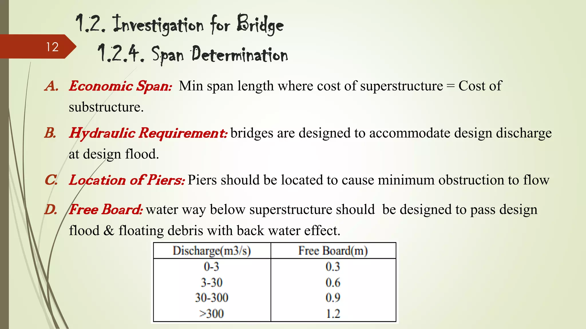
The document discusses bridge construction and provides details on bridge types and selection. It begins with an introduction to bridge engineering and the investigation process for bridge sites, including preliminary surveys, site selection factors, and elements of site investigation.
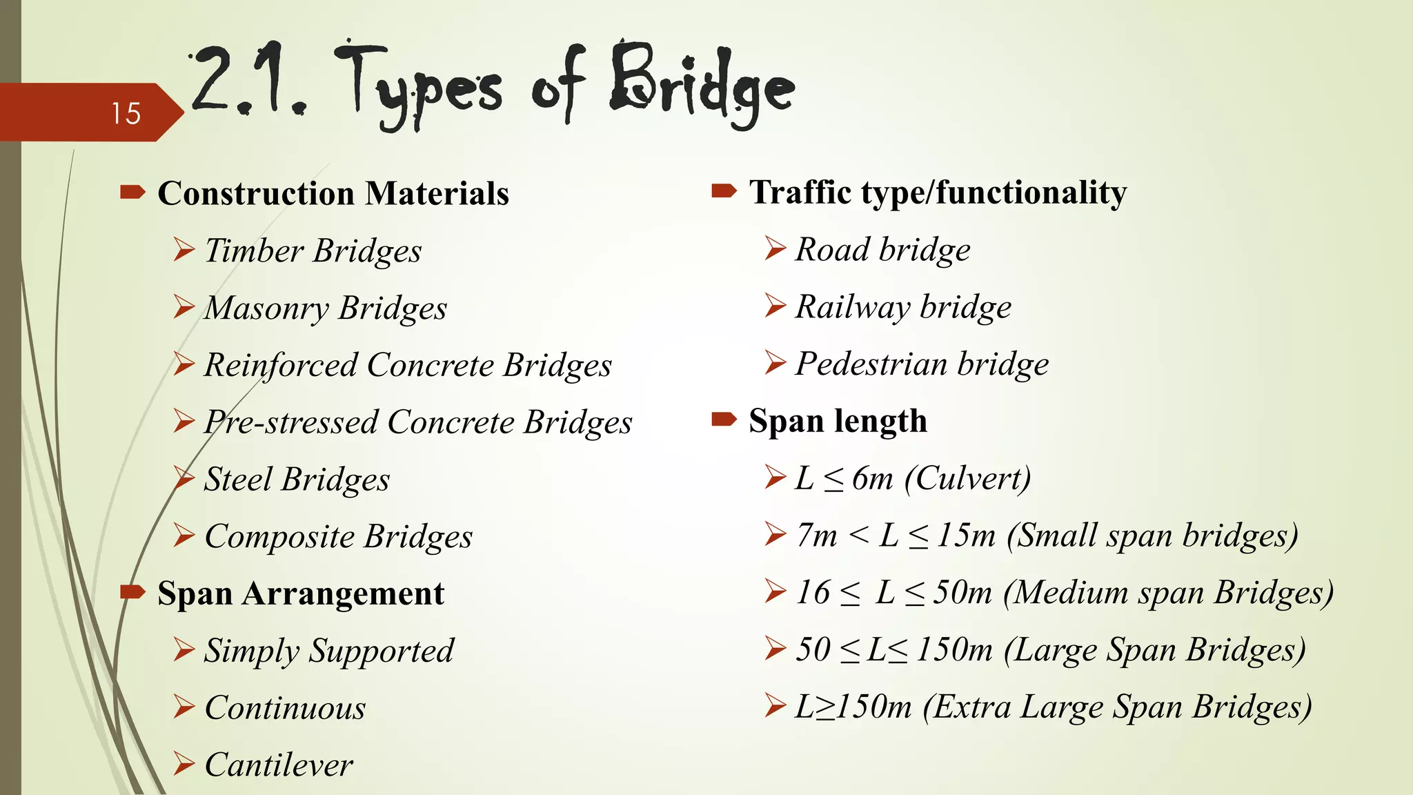
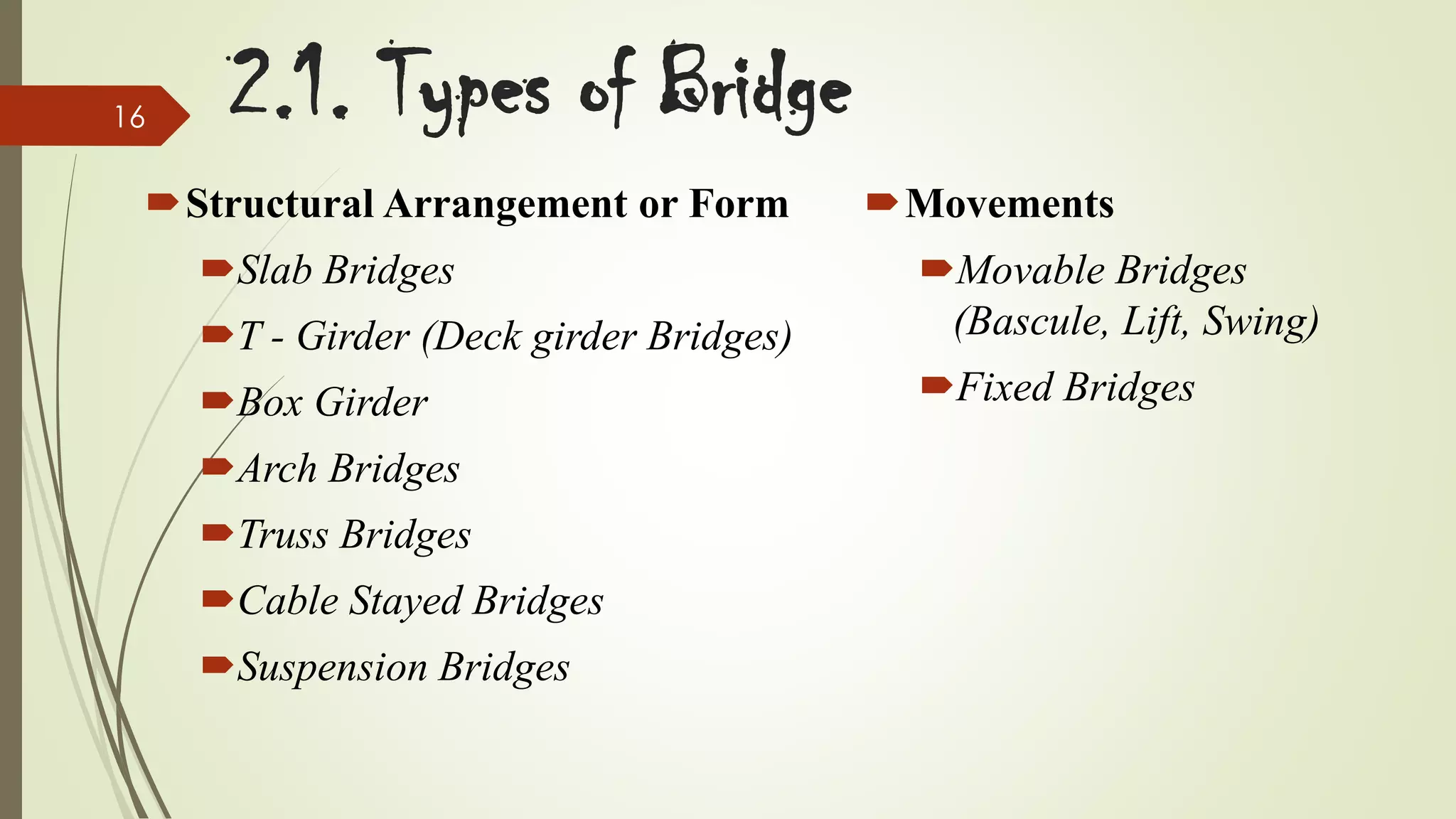
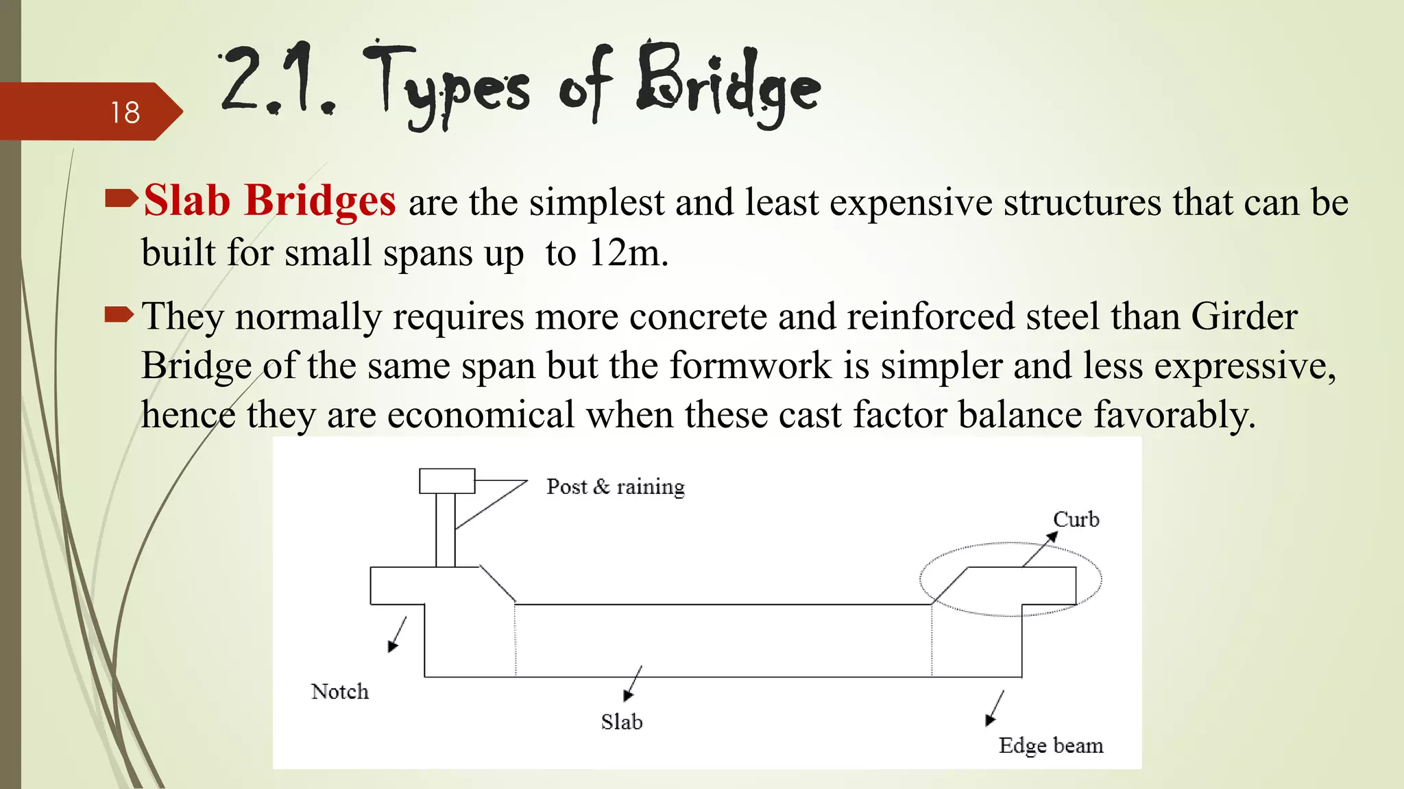
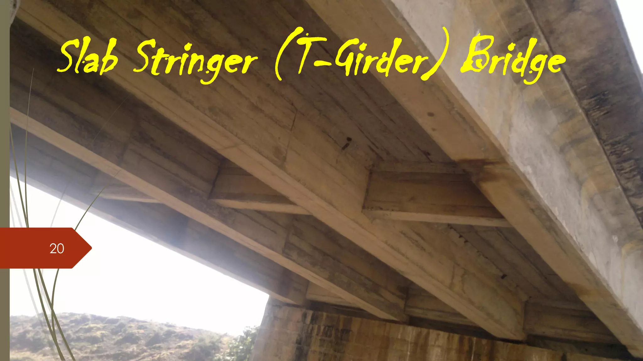
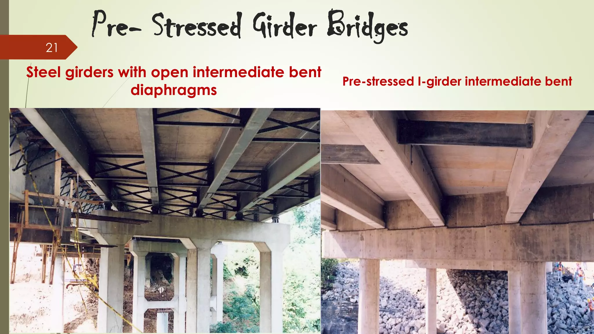
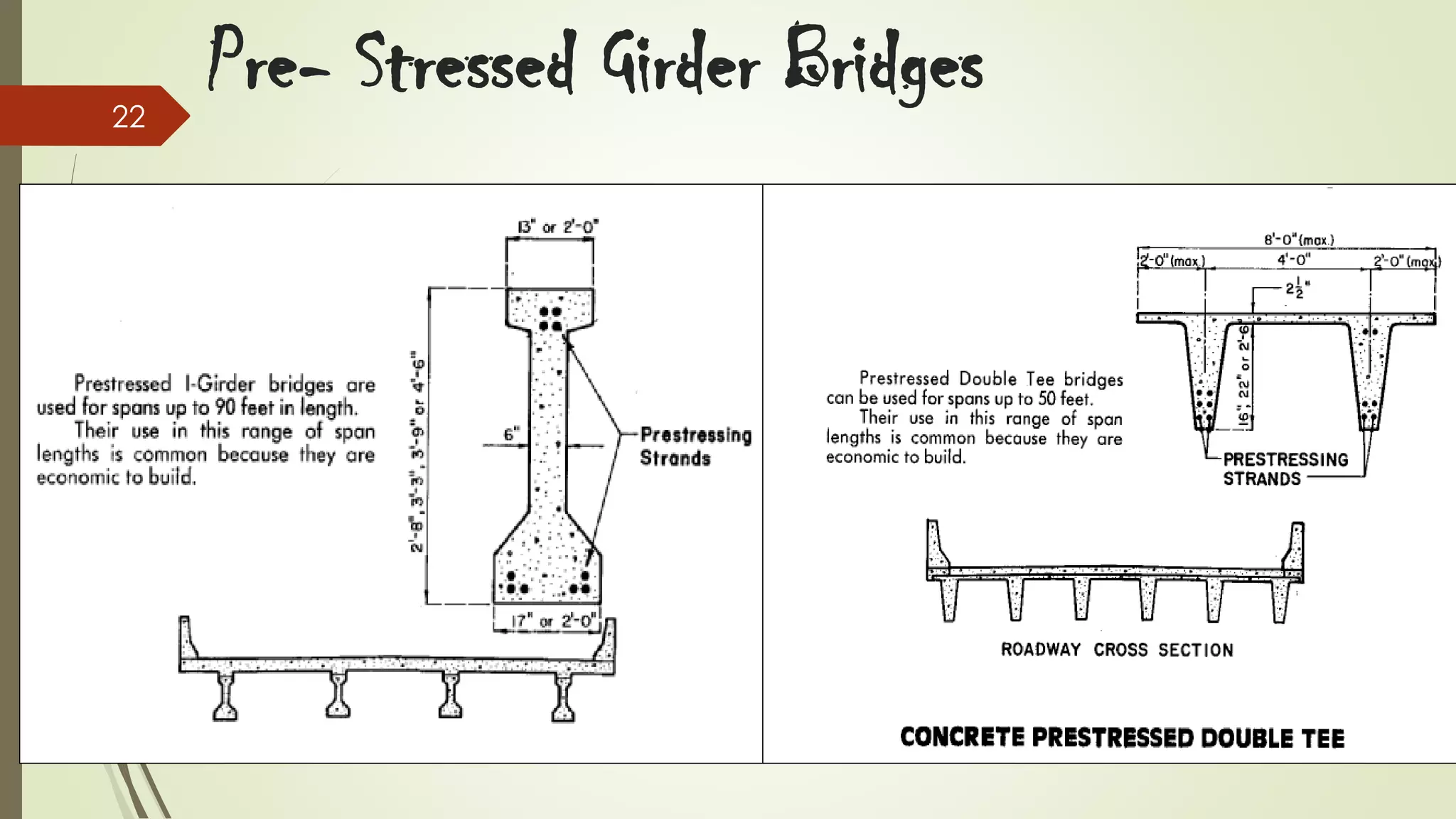
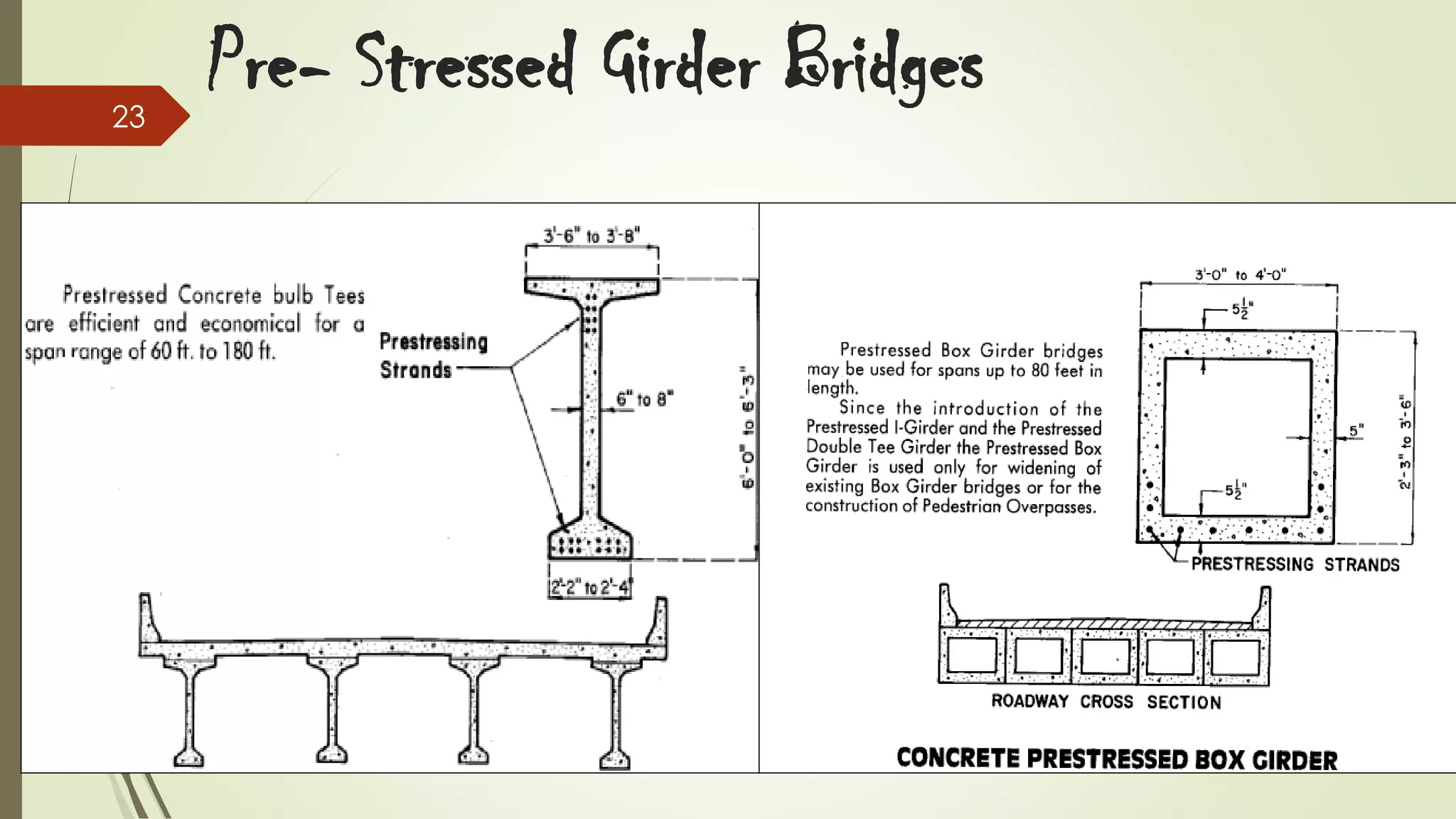
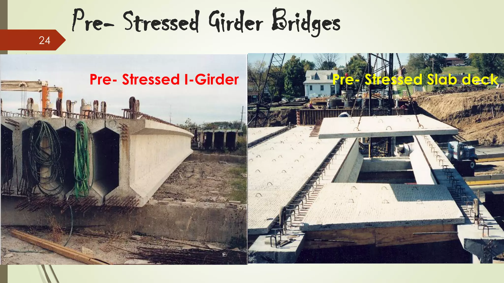
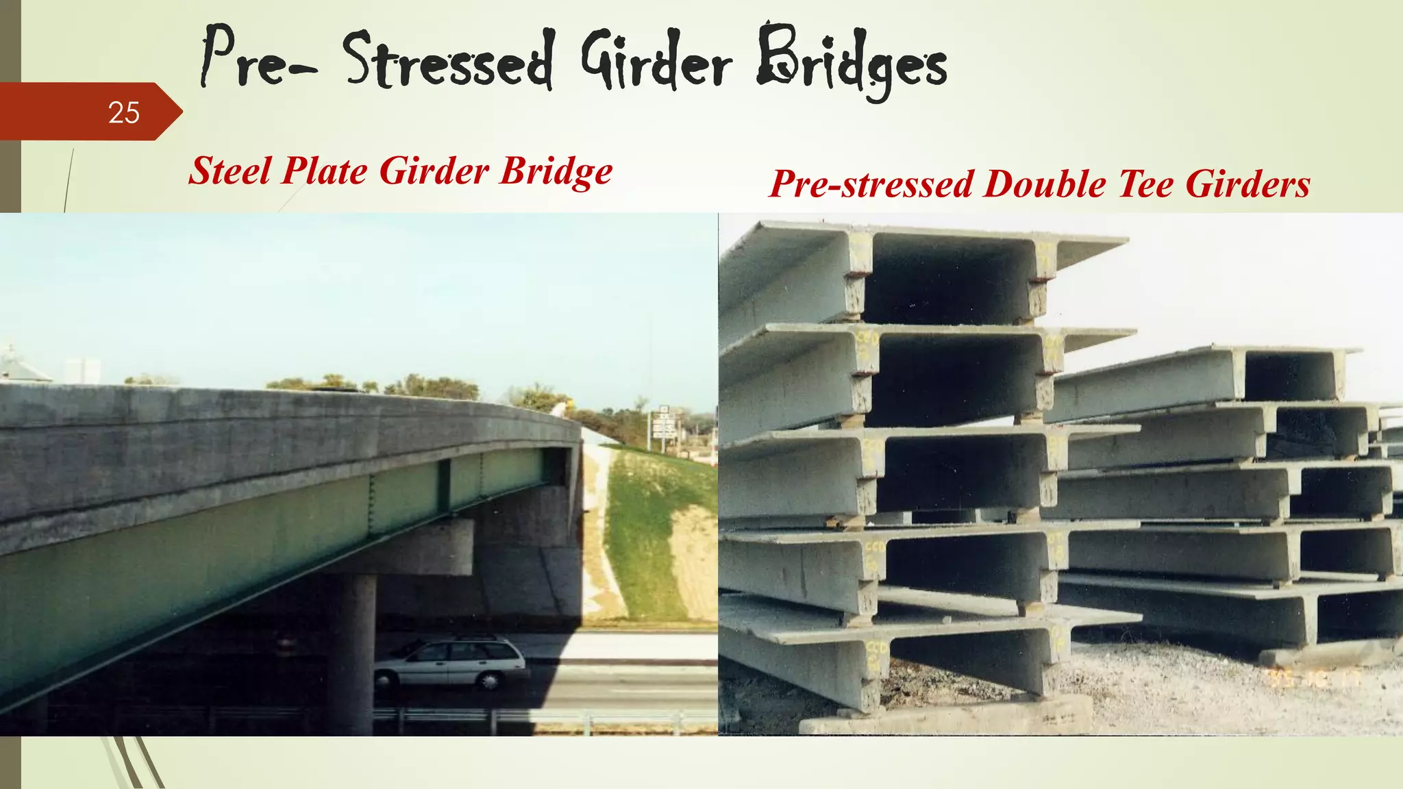
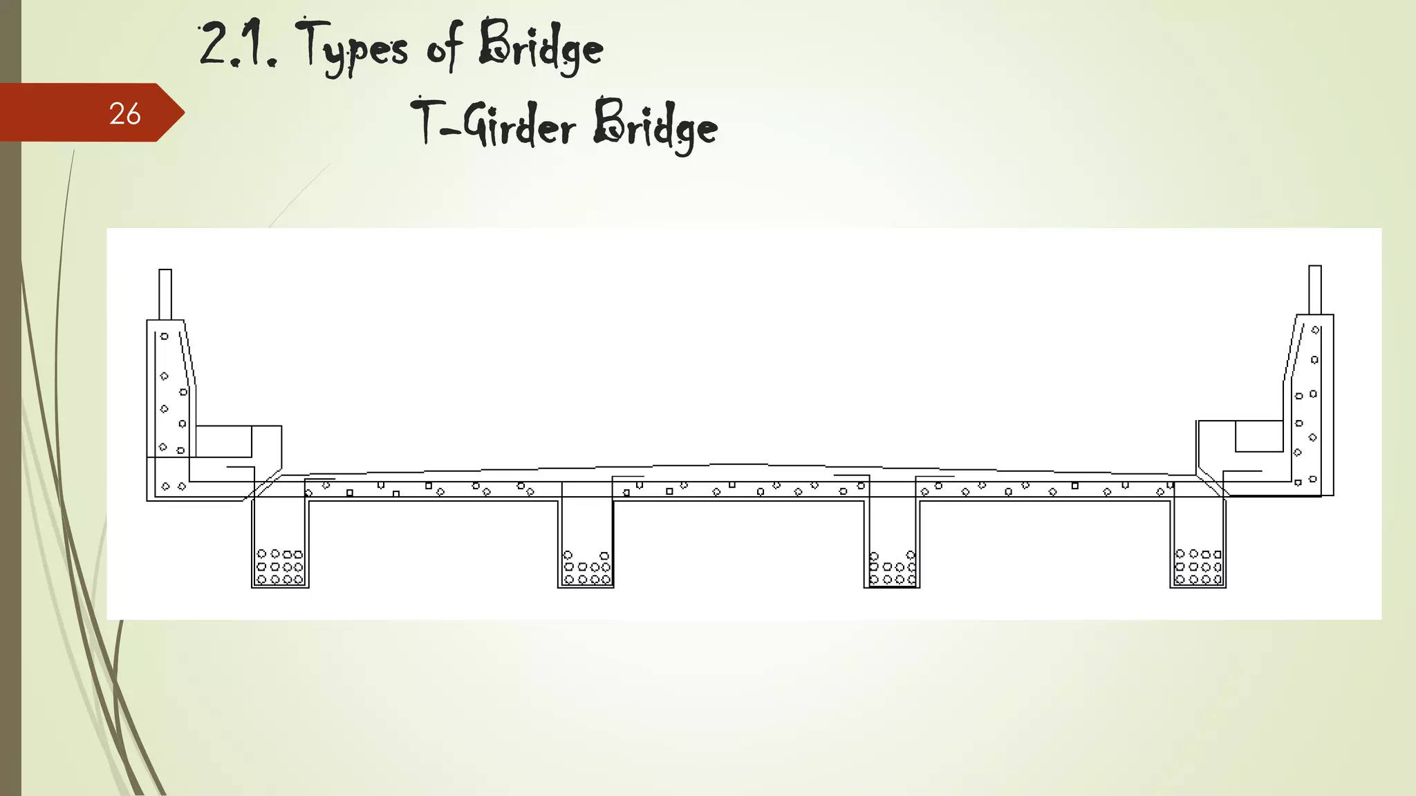
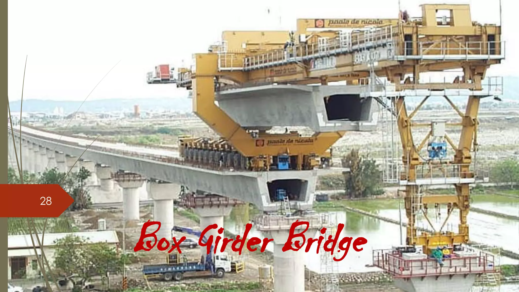
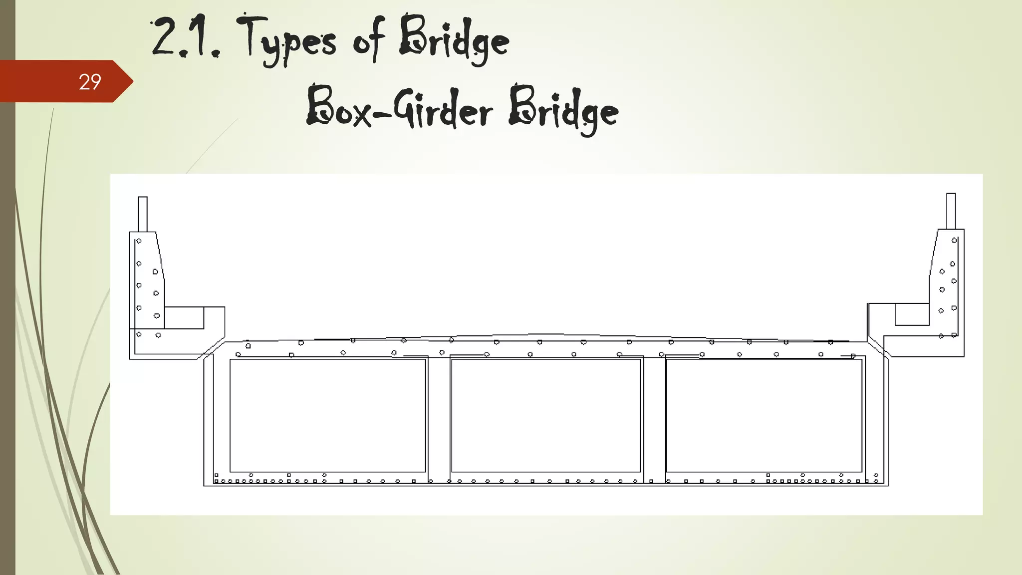
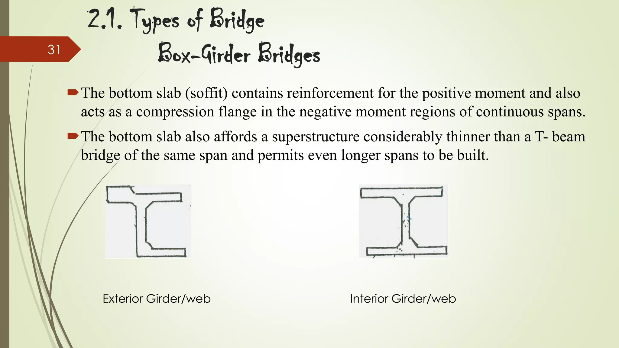
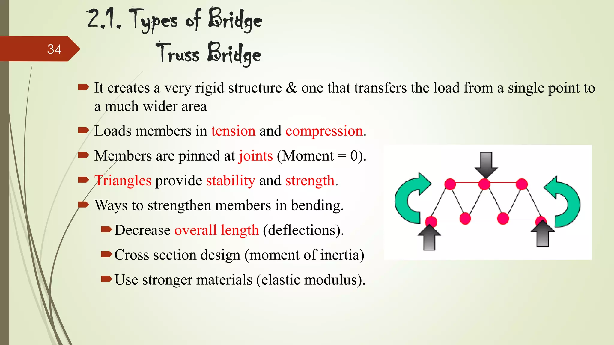
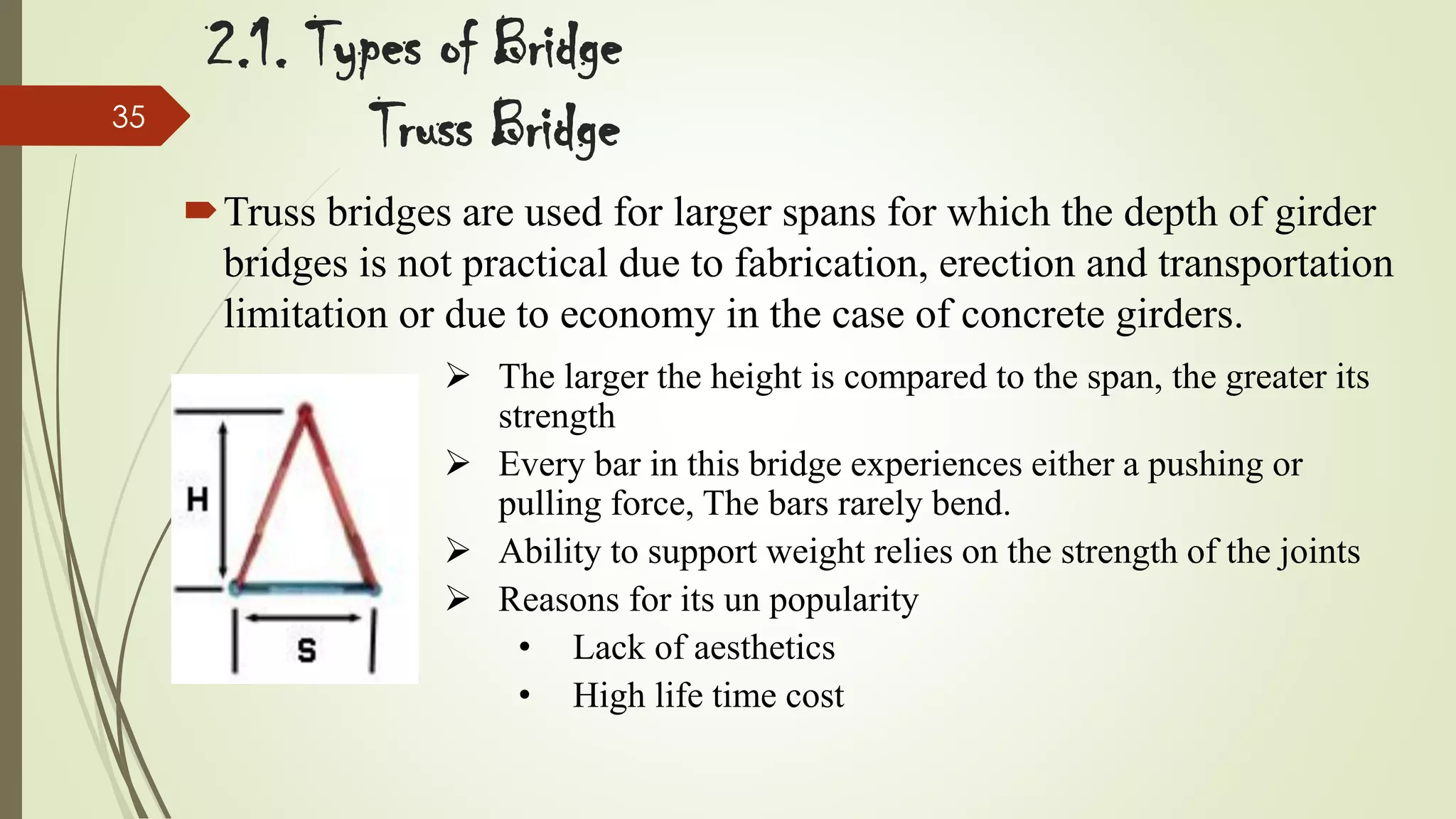
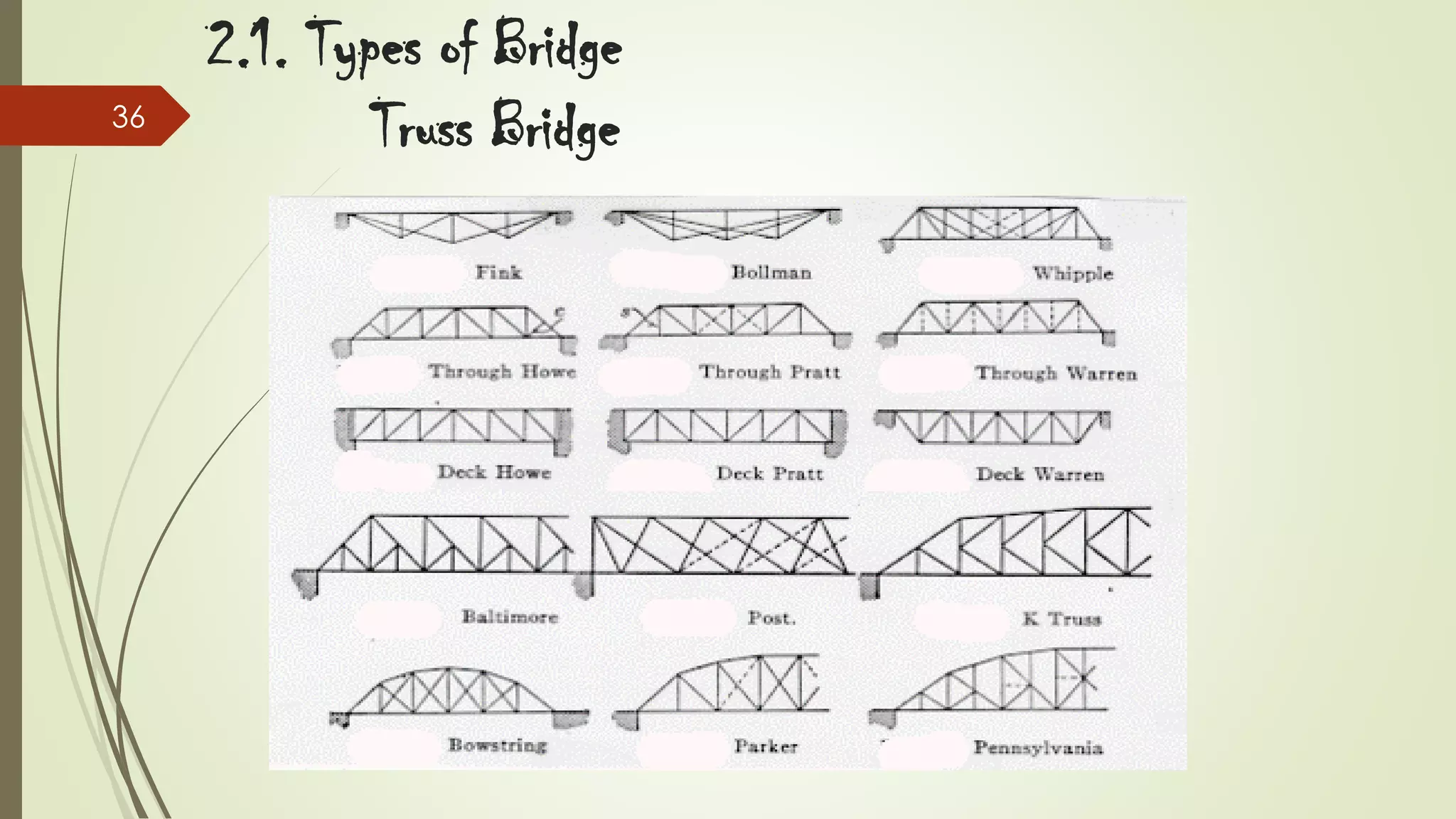
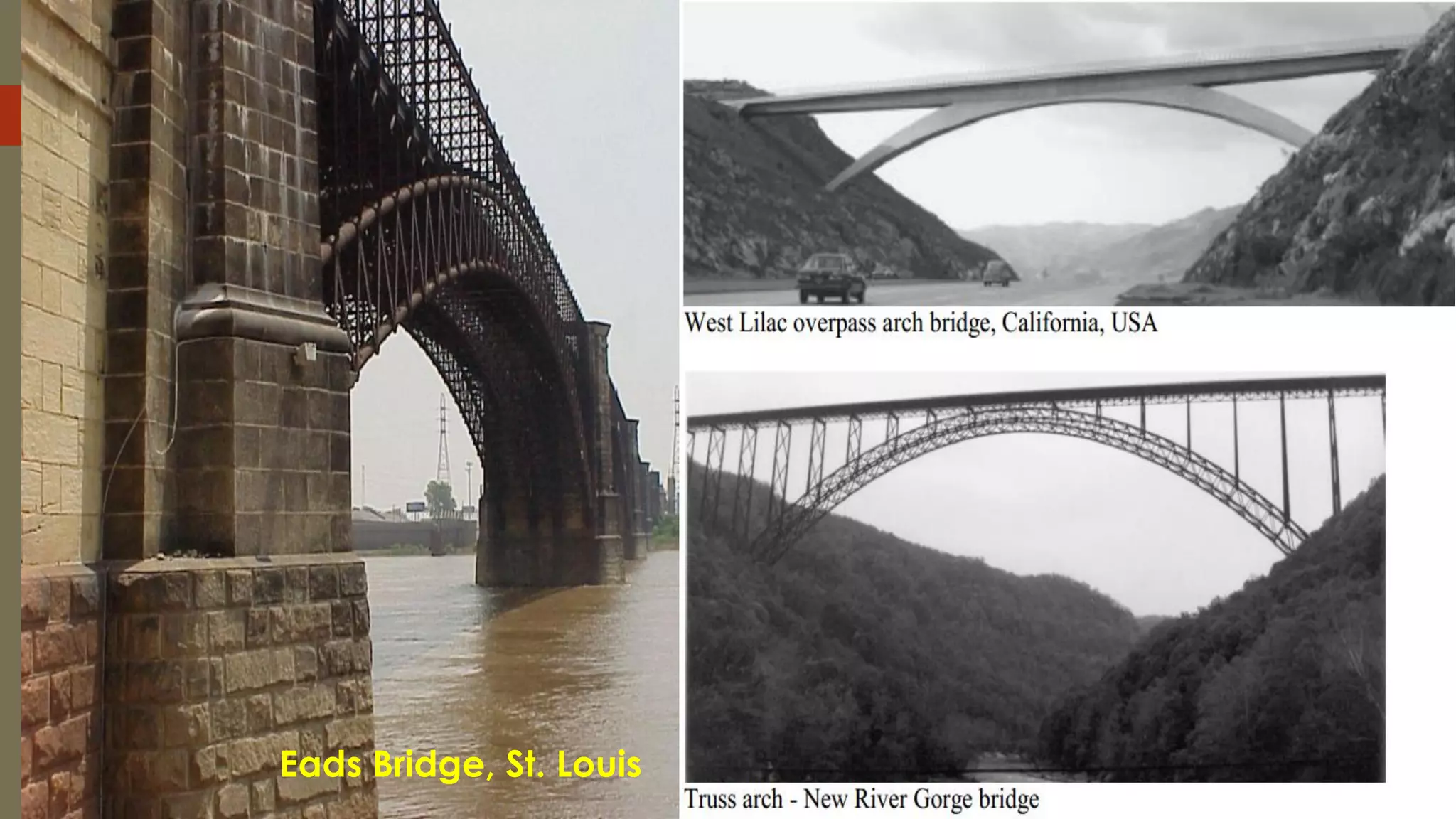
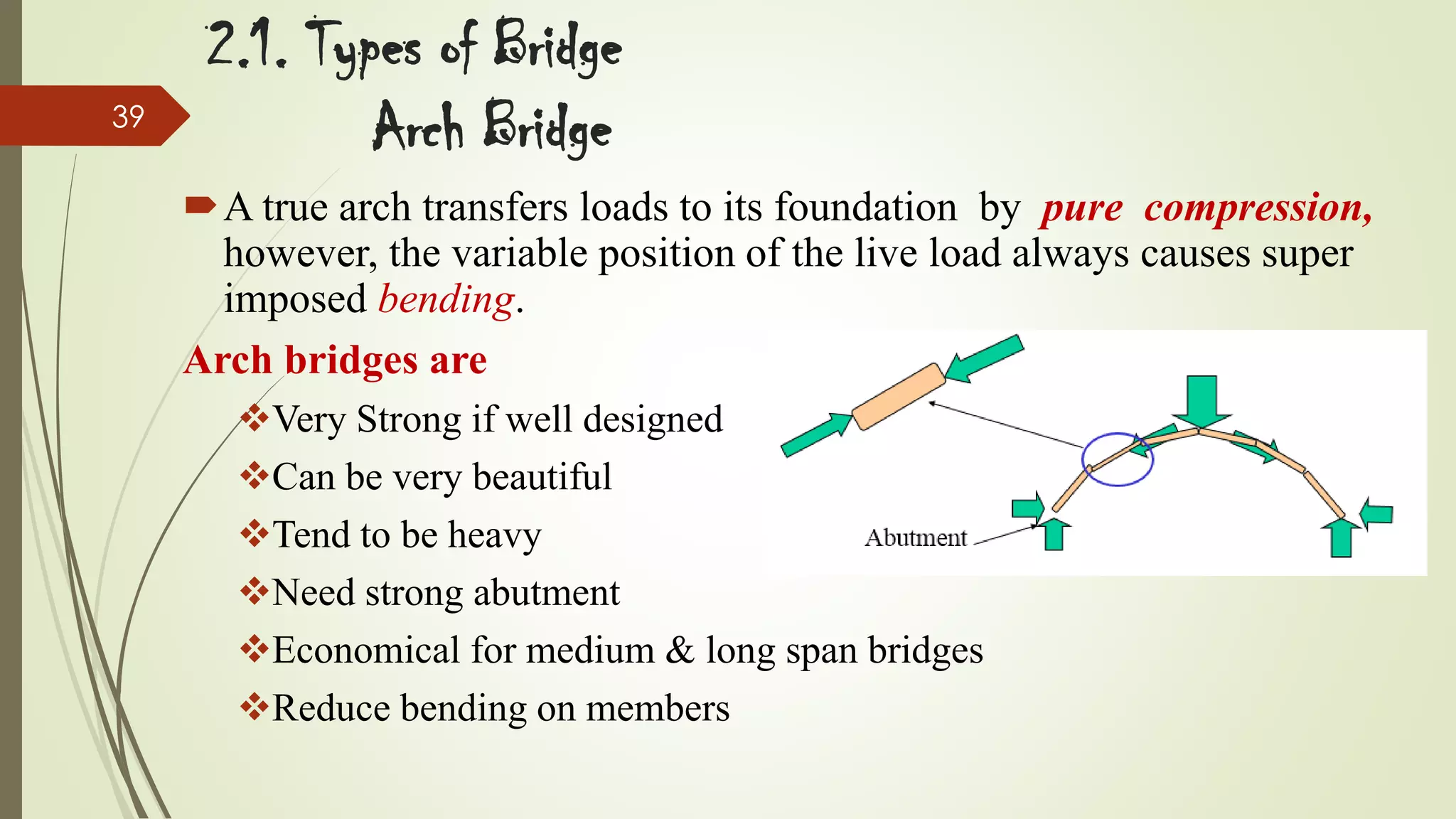
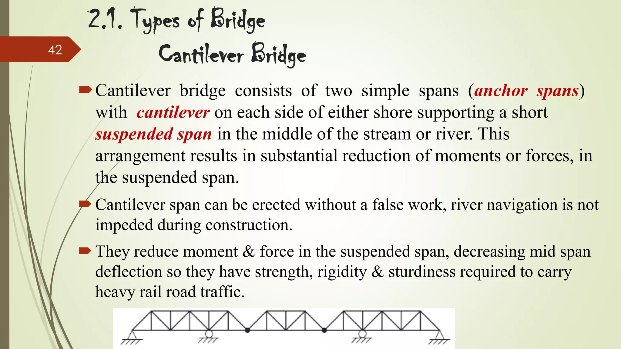
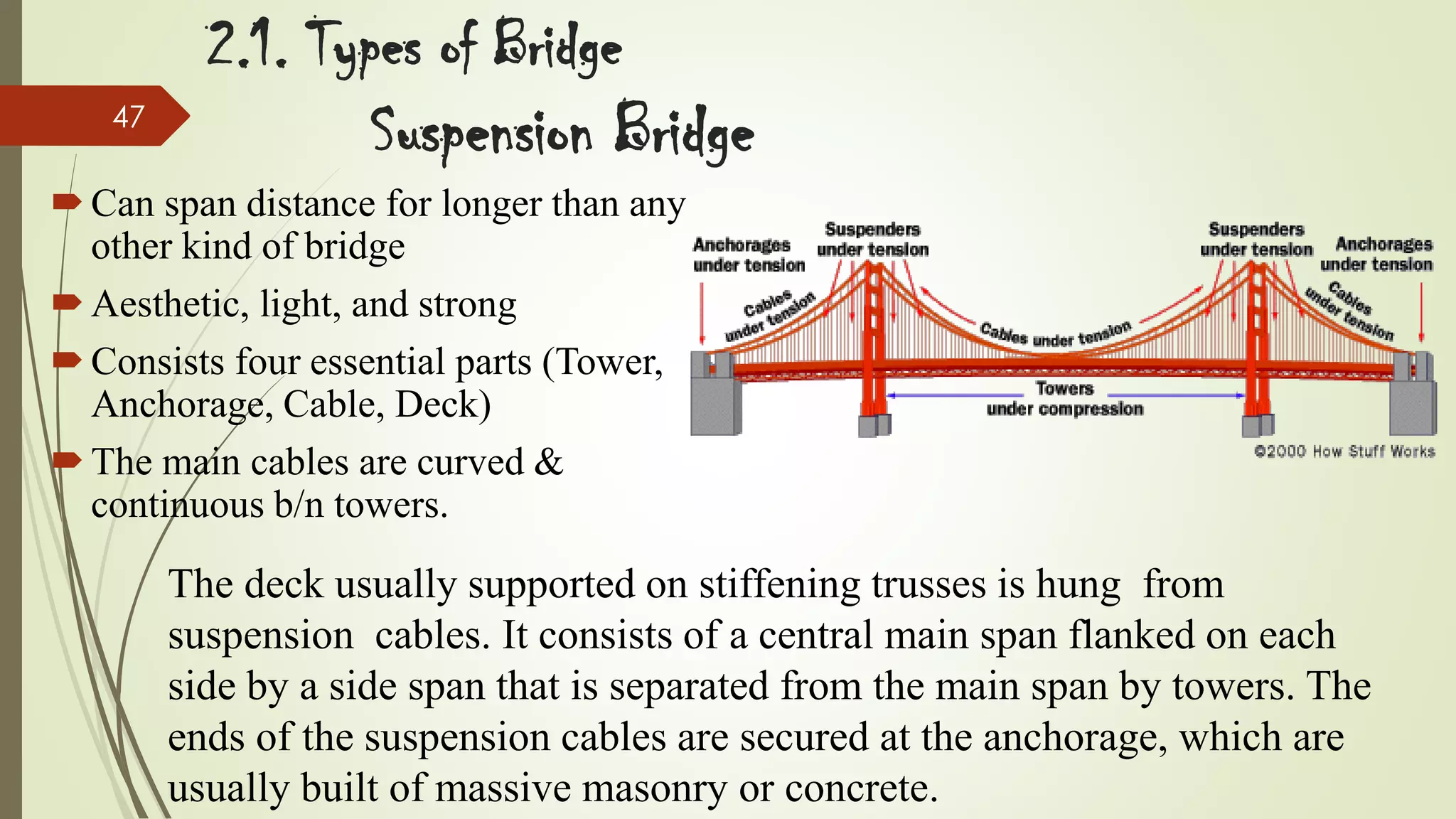
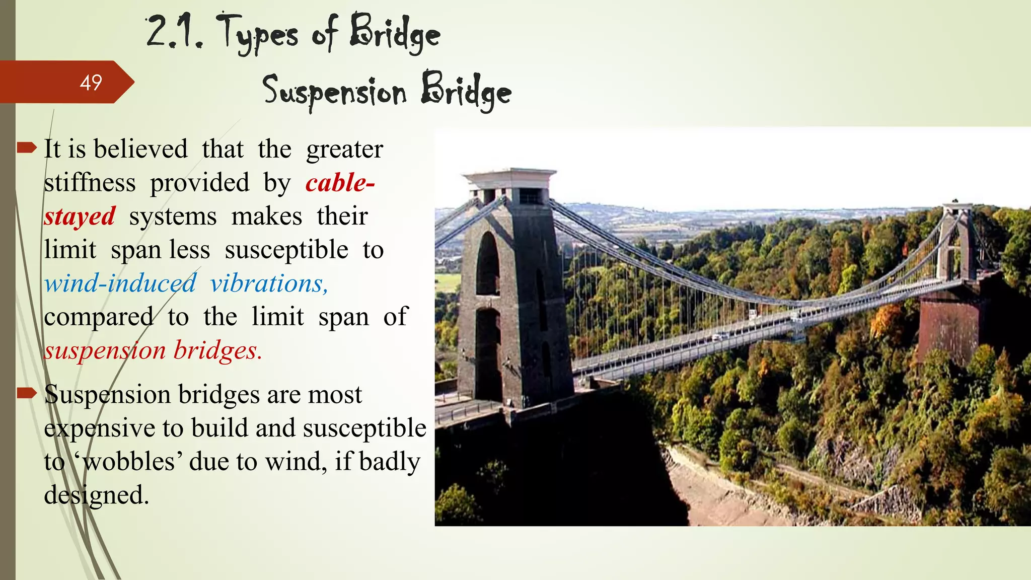
It then covers the major types of bridges based on materials, span arrangement, and structural form - including slab bridges, T-girder bridges, box girder bridges, truss bridges, arch bridges, cantilever bridges, cable-stayed bridges, and suspension bridges. For each type, it provides a brief description and examples.
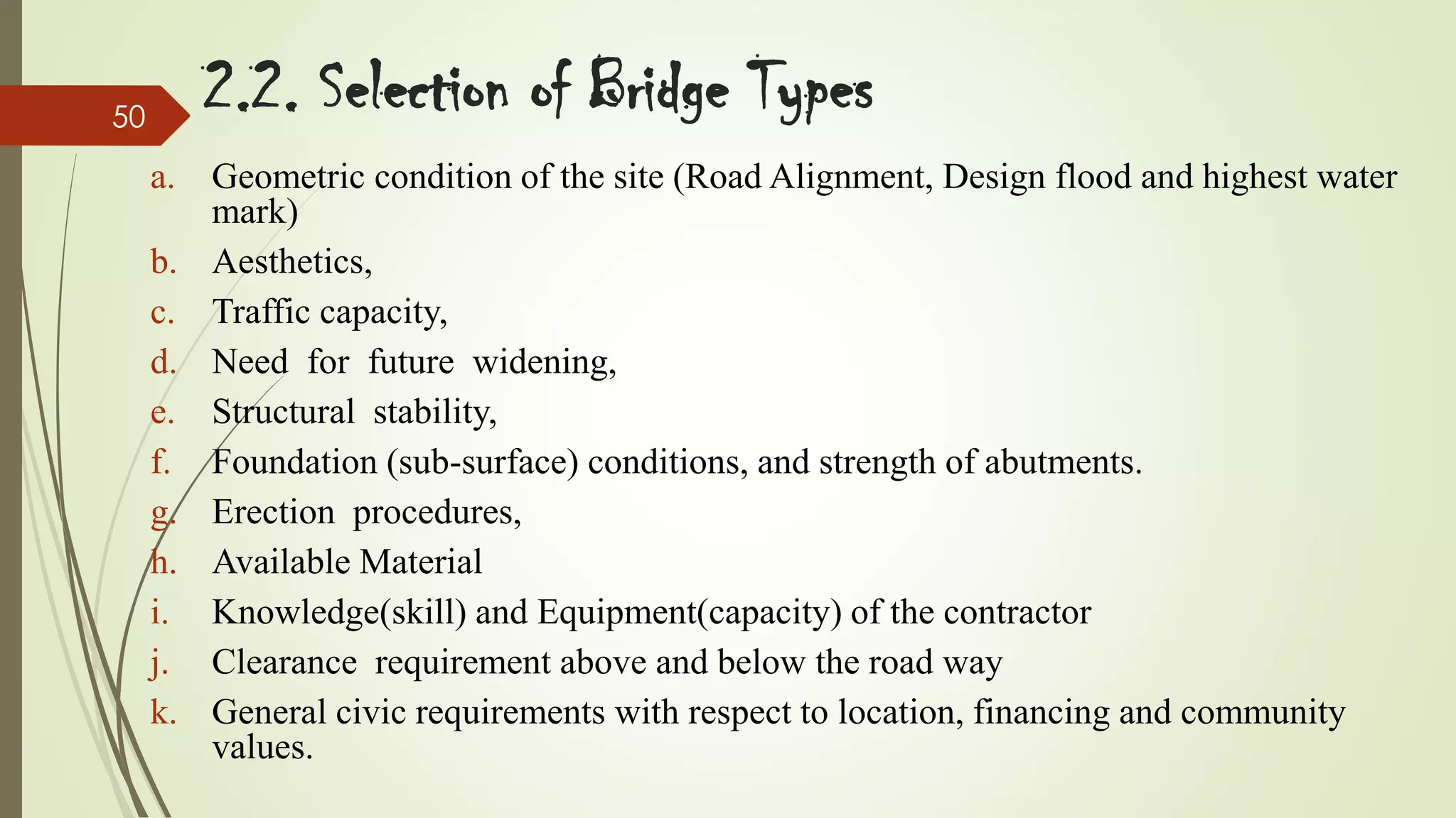
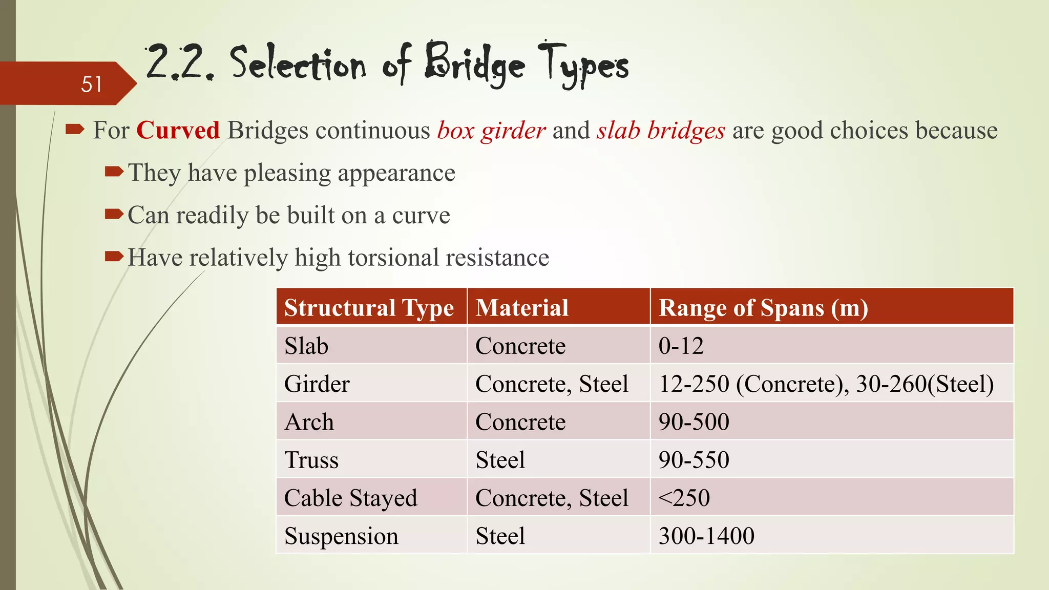
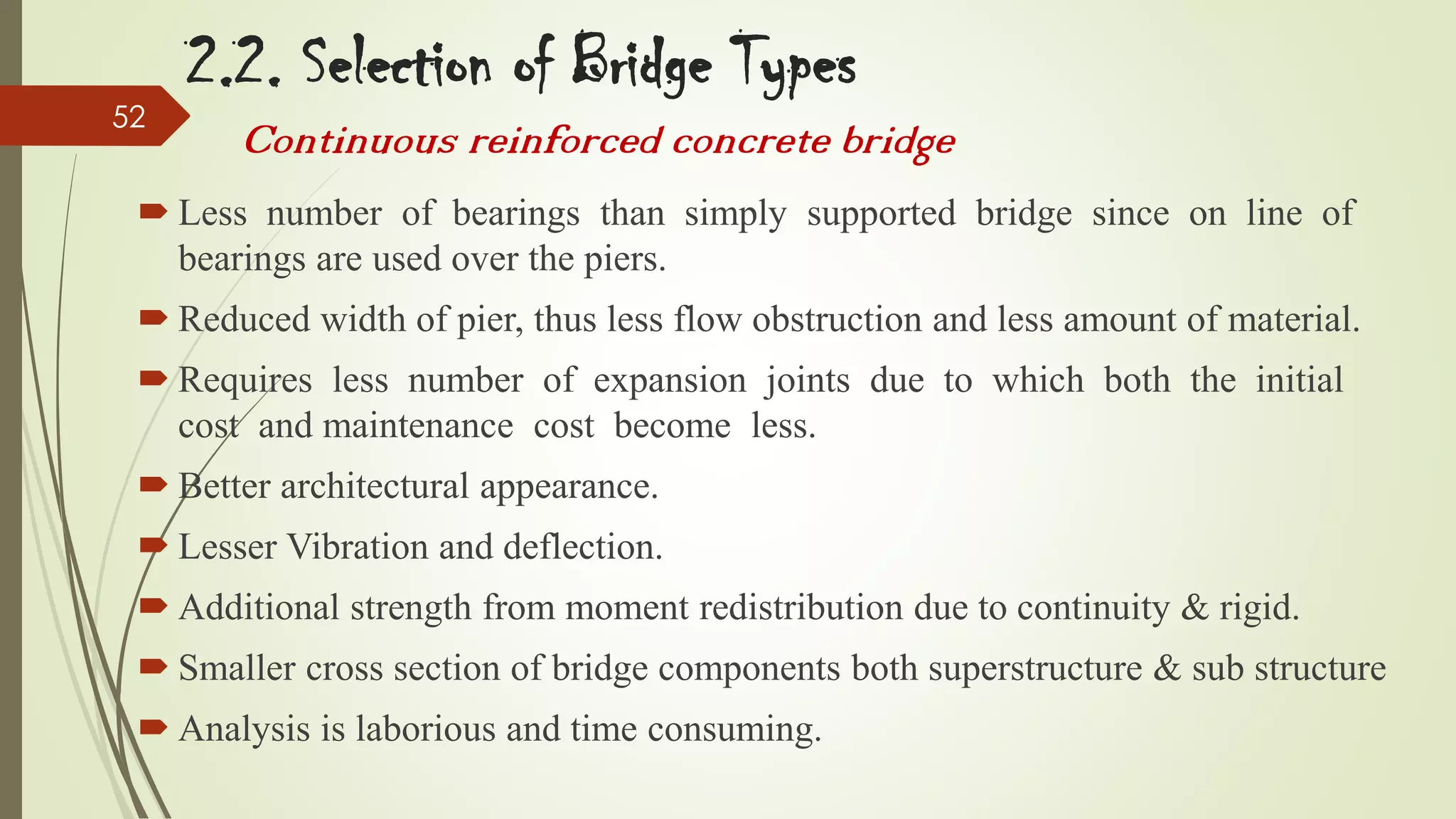
Finally, it lists the key factors to consider for selecting the appropriate bridge type for a given site, such as geometric conditions, aesthetics, traffic