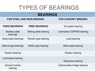
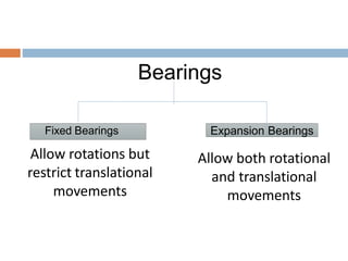
1
PREPARED BY : ASST. PROF. VATSAL D. PATEL
MAHATMA GANDHI INSTITUTE OF
TECHNICAL EDUCATION &
RESEARCH CENTRE, NAVSARI.
INTRODUCTION
 A bridge is a structure built to span physical
obstacles such as a body of water, valley, or
road, for the purpose of providing passage
over the obstacle.
FACTORS AFFECTING
SELECTION OF A SITE FOR
BRIDGE
 Width of river
 Foundations
 River banks
 Material and labor
 Velocity of flow
 Free board
 Minimum obstruction to waterway
 Absence of scouring and silting
STAGES OF BRIDGE
INVESTIGATION
 Reconnaissance stage
 Preliminary stage
 Detailed survey and project report
RECONNAISSANCE STAGE
 This is a pre-feasibility study, which studies the
entire reach of the river, that must be crossed;
to find out best and suitable position for bridge
location.
 The direct assessment of the site is made to
understand the location features (local
criteria), studying the existing and growth of
traffic with the help of surveys, knowing
information from the people residing, simple
routes and short cuts in the area, river flow
and its spread are also studied.
PRELIMINARY STAGE
 The total length of the bridge
 The length of approaches
 If detours are present, their respective savings
 The anticipated volume of traffic
 The distance to the nearby city or town from
the site
 Expected bridge project period
 The nature of stream flowing into the site
PRELIMINARY STAGE
 The nature and behavior of soil strata for
foundation
 The construction problems existing with
bridges or approaches
 Maintenance for the bridges or approaches if
any
 The internal rate of return or the cost benefit
ratio
 The impact on the environment.
DETAILED SURVEY AND PROJECT
REPORT
 This stage is the final stage of planning in the
bridge construction, before the
commencement of the construction work. Full
investigation from the roots is taken and
documented. The investigations conducted
are:
 Ground survey
 Soil exploration- foundation details
 Hydrological data
 Model studies and analysis
DEFINATION
 LENGTH OF THE BRIDGE : The length of a
bridge structure will be taken as the overall
length measured along the center line of the
bridge from end to end of the bridge deck.
 LINEAR WATERWAY : The linear waterway of
a bridge shall be the length available in the
bridge between extreme edge of a water
surface at the highest flood level, measured at
right angles to the abutment faces.
DEFINATION
 NATURAL WATER WAY : The unobstructed
area of the river or stream through which water
flows at the bridge site is called natural water
way.
 AFFLUX : Due to construction of the bridge
there is a contraction in waterway. This results
in rise of water level above its normal level
while passing under the bridge. The rise is
known as afflux.
DEFINATION
 FREE BOARD : Free board at any point is the
difference between the highest flood level after
allowing for afflux, if any, and the formation
level of road embankment on the approaches
or top level of guide bunds at that point.
 LOW WATER LEVEL (L.F.L) : The low water
level is the level of water surface obtained
generally in the dry season.
DEFINATION
 HIGHEST FLOOD LEVEL (H.F.L) : It is the
level of the highest flood ever recorded or the
calculated level for the highest possible flood.
 ECONOMIC SPAN : The span, for which the
total cost of bridge structure is minimum is
known as economic span.
COMPONENTS OF BRIDGE
 Substructure - includes the piers, the
abutments and the foundations.
 Superstructure - consists of the deck structure
itself, which support the direct loads due to
traffic and all the other permanent and
variable leads to which the structure is
subjected.
 Adjoining structure - includes approaches ,
river training works, guard stones.
COMPONENTS OF BRIDGE
CLASSIFICATION OF
BRIDGES
 According to functions : aqueduct, viaduct, highway,
pedestrian etc.
 According to materials of construction : reinforced
concrete, prestressed concrete, steel, composite,
timber etc.
 According to form of superstructure : slab, beam,
truss, arch, suspension, cable-stayed etc.
 According to interspan relation : simple, continuous,
cantilever.
 According to the position of the bridge floor relative to
the superstructure : deck, through, half-through etc.
 According to method of construction : pin-connected,
riveted, welded etc.
CLASSIFICATION OF
BRIDGES
 According to road level relative to highest flood
level : high-level, submersible etc.
 According to method of clearance for navigation :
movable-bascule, movable-swing, transporter
 According to span : short, medium, long, right,
skew, curved.
 According to degree of redundancy : determinate,
indeterminate
 According to type of service and duration of use :
permanent, temporary bridge, military
BASED ON TYPE OF
SUPERSTRUCTURE
 Suspension bridges are suspended from
cables. The earliest suspension bridges were
made of ropes or vines covered with pieces of
bamboo. In modern bridges, the cables hang
from towers that are attached to caissons or
cofferdams.
ARCH BRIDGE
 Arch bridges have abutments at each end.
The weight of the bridge is thrust into the
abutments at either side.
BEAM BRIDGE
 Beam bridges are horizontal beams supported
at each end by substructure units and can be
either simply supported when the beams only
connect across a single span, or continuous
when the beams are connected across two or
more spans.
TRUSS BRIDGE
 A truss bridge is a bridge whose load-bearing
superstructure is composed of a truss. This
truss is a structure of connected elements
forming triangular units.
BEARINGS
 Bearings are important elements in large
infrastructures such as bridges, heavy
buildings and high rise buildings, ensuring
load transfer, movement, rotation, vertical or
horizontal restraints as required by the design
at critical locations in a structure.
 Bridge Bearings are structural devices
positioned between the bridge superstructure
and the substructure.
BEARINGS
 Their principal functions are as follows:
 To transmit loads from the superstructure to
the substructure.
 To accommodate relative movements
between the superstructure and the
substructure.
FUNCTIONS OF BRIDGE
BEARINGS
 Connects the bridge superstructure to the
substructure.
 Accommodates and transfers dynamic forces
and vibrations without causing wear or
destruction to the substructure.
 Enables movement (translational, vertical or
rotational) of the bridge structure in reactions
to loads.
 Controls the movement in bridge structure;
direction and degree wise.
FUNCTIONS OF BRIDGE
BEARINGS
 Ensures that deformations, which occur in the
superstructure of the bridge, do not lead to
large forces and moments in the substructure.
 Can be used to adjust the dynamic properties
of the bridge.
 Bearings reduce shear on the head of the
piers, viaducts or abutments.
 Recent bridge bearings are designed to act as
seismic protectors that arrest and dissipate
energy during earthquakes and other seismic
activities.
TYPES OF BEARINGS
BEARINGS
FOR STEEL AND IRON BRIDGES FOR CONCRET BRIDGES
FIXED BEARINGS FREE BEARINGS Tar paper bearing
Shallow plate
bearings
Sliding plate bearing Laminated COPPER bearing
Deep base bearings Rocker type bearing Lead bearing
Steel hinge bearings Roller type bearing Slide plate bearing
Rocker bearing Rubber bearing
Laminated bearing
Neoprene bearing
Cement mortar
bearing
Submersible bridge bearing
Bearings
Expansion BearingsFixed Bearings
Allow rotations but
restrict translational
movements
Allow both rotational
and translational
movements
SLIDING PLATE BEARING
 A sliding bearing utilizes one plane metal
plate sliding against another to accommodate
translations.
 The sliding bearing surface produces a
frictional force that is applied to the
superstructure, the substructure, and the
bearing itself.
 To reduce this friction force, PTFE
(Polytetrafluorethylene) is often used as a
sliding lubricating material.
SLIDING PLATE BEARING
 Sliding bearings can be used alone or more
often used as a component in other types of
bearings.
 Pure sliding bearings can only be used when
the rotations caused by the deflection at the
supports are negligible.
 A guiding system may be added to a sliding
bearing to control the direction of the
movement.
SLIDING PLATE BEARING
ROCKER BEARING
 A rocker bearing is a type of expansion
bearing that comes in a great variety.
 It typically consists of a pin at the top that
facilitates rotations, and a curved surface at
the bottom that accommodates the
translational movements
 Rocker and pin bearings are primarily used in
steel bridges
ROCKER BEARING
 The moment and lateral forces induced from
the movement of these bearings are very
small and negligible.
 However, metal bearings are susceptible to
corrosion and deterioration. A corroded joint
may induce much larger forces.
 Regular inspection and maintenance are,
therefore, required.
ROCKER BEARING
ROLLER BEARING
 Roller bearings are composed of one or more
rollers between two parallel steel plates.
 Single roller bearings can facilitate both
rotations and translations in the longitudinal
direction, while a group of rollers would only
accommodate longitudinal translations
ROLLER BEARING
 Single roller bearings are relatively cheap to
manufacture, but they only have a very limited
vertical load capacity.
 Multiple roller bearings, on the other hand,
may be able to support very large loads, but
they are much more expensive.
 Like rocker and pin bearings, roller bearings
are also susceptible to corrosion and
deterioration. Regular inspection and
maintenance are essential
ROLLER BEARING
INTRODUCTION TO STEEL
BRIDGES
 The steel girder bridge is a structure in which a floor system and
roadway, concrete or timber, is supported by girders, usually
rolled section beams which are plain or encased in concrete
 These are normally used for railways and rarely for highways
 Following data should be collected prior to the erection of these
bridges:
 Time estimate for the construction of a bridge
 Condition of proper equipment and machinery
 Condition of bridge site
 Facility for transportation and storage of materials at bridge
site
 Necessary supporting system for superstructure
 Availability of steel structures
 Width and depth of flow in the river
ERECTION OF STEEL GIRDER
BRIDGES
Methods for erection of steel bridges
Erection by Lifting Method
Erection by Staging
Erection by Floating
Erection by Rolling
Erection by Launching of single girder span
ERECTION OF BRIDGES
Methods:
Erection by lifting method
Steel girders up to span of 30m can be easily erected if the height is 5 to 6
m.
This method is suitable for rivers which are dry for the most part of the
year
A platform is created by filling earth to sufficient height and leveled
Girders are assembled on the river bed and field riveted/bolted
They are lifted into position by means of stiff-leg derrick cranes or ordinary
Rope worked from anchored crab winches
The flooring and the bracings are then field connected to the girders
placed in position
ERECTION BY LIFTING
ERECTION OF STEEL
BRIDGES
 Methods
 Erection by Staging:
 Favorable conditions:
 Depth of water in the river is shallow
 Height of superstructure above the river should not be
excessive
 Span should be simply supported
 Staging consists of trestle frames which may be of steel or
timber
 Iron staging is lighter than timber staging and, therefore, can be
easily transported
 Staging is suitably designed and after it is constructed, the
erection of steel girders is commenced on the staging.
ERECTION BY STAGING
ERECTION OF STEEL
BRIDGES
 Methods
 Erection by Floating:
 Favourable conditions for this method are:
 Depth of water in the river is more
 Floating barges/pontoons are used to carry the steel girders
 Bridge is assembled onthe barges and is floated into position when
complete.
 The barges are so positioned that span is over the final alignment, when
the jacks are used to lower the span on the bearings.
 Finally the barges are sunk by flooding the tanks.
COLEMAN BRIDGE, YORK RIVER IN
YORKTOWN
ERECTION OF STEEL
BRIDGES
 Methods
 Erection by Rolling:
 This method is adopted for erection of continuous girders on deep
gorges
 First span near the abutment is erected by any one method of
erection
 Girders of the first span are brought to the requires position by
rolling them from the abutment through the erected span.
 This method is also known as the incremental launching method
and has become very popular for the concrete girders.
 Second span is cantilevered when it projects from the erected
span and acquires counter weight for its stability.
 This counter weight is provided by the successive span
connected to it and its back
ERECTION OF STEEL
BRIDGES
 Erection by Launching of single girder span
 Each girder is first assembled on a track of rollers
behind one of the abutments and is cantilevered as
far as possible over the span.
 The lifting blocks are then fastened
to the outmost point of the girder and the heavy wire
is coupled to the winch.
 Rear end of the girder is tied to another winch which
is released slowly so that sudden forward motion
may no take place.
ERECTION BY LAUNCHING OF
KURILPA BRIDGE, BRISBANE,
AUSTRALIA
ERECTION OF STEEL TRUSS
BRIDGES
These bridges are erected with the help of a stiff derrick traveller and two false
work bents.
Erection procedure may be defined in four stages:
 First stage
• Erase false work bent T1.
• Assemble the section AB.
 Second stage:
• Move traveller (crane) to B.
• Erase false work bent T2.
• Assemble the section BC.
 Third stage
• Move traveller to C.
• Remove false work bent T1 from B and erect it at D.
• Assemble the section CD.
 Fourth stage:
• Move traveller to D.
• Assemble the section DE.
• Release the false work bent T1 and T2.
THE SUSPENSION BRIDGE ERECTION
Erection of towers and anchorages
(ii) Providing cat walk
(iii) Spinning of the main cables and fixing them with the anchorages and
towers.
(iv) Erection of suspenders and stiffening truss
(v) Construction of flooring system
After erection of the towers and completion of the anchorage
arrangement, a catwalk is provided with timber platform over ropes
which are placed concentric with main cables. A tramway system is
installed over the cat-walk for spinning the wires for the cables.
At each anchorage, a spinning wheel is attached to the tramway system.
The spinning of the wires (which is known as “aerial spinning”) is done
by fastening the ends with the
anchorages and then making loops over the spinning wheels.
The spinning wheels are pulled along the catwalk and over the towers
to the opposite anchorages. The wires are then attached to the
anchorages and this procedure is repeated till all the wires of the strand
are carried over the towers to the anchorages.
The ensure strand is then banded up at intermediate places. After
completing all the strands of the cables in the way as described, the
cable is compacted by squeezing to the form of a circular section.
56

6. BRIDGE ENGINEERING (RBT) 2160603 GTU

  • 1.
    1 PREPARED BY :ASST. PROF. VATSAL D. PATEL MAHATMA GANDHI INSTITUTE OF TECHNICAL EDUCATION & RESEARCH CENTRE, NAVSARI.
  • 2.
    INTRODUCTION  A bridgeis a structure built to span physical obstacles such as a body of water, valley, or road, for the purpose of providing passage over the obstacle.
  • 3.
    FACTORS AFFECTING SELECTION OFA SITE FOR BRIDGE  Width of river  Foundations  River banks  Material and labor  Velocity of flow  Free board  Minimum obstruction to waterway  Absence of scouring and silting
  • 4.
    STAGES OF BRIDGE INVESTIGATION Reconnaissance stage  Preliminary stage  Detailed survey and project report
  • 5.
    RECONNAISSANCE STAGE  Thisis a pre-feasibility study, which studies the entire reach of the river, that must be crossed; to find out best and suitable position for bridge location.  The direct assessment of the site is made to understand the location features (local criteria), studying the existing and growth of traffic with the help of surveys, knowing information from the people residing, simple routes and short cuts in the area, river flow and its spread are also studied.
  • 6.
    PRELIMINARY STAGE  Thetotal length of the bridge  The length of approaches  If detours are present, their respective savings  The anticipated volume of traffic  The distance to the nearby city or town from the site  Expected bridge project period  The nature of stream flowing into the site
  • 7.
    PRELIMINARY STAGE  Thenature and behavior of soil strata for foundation  The construction problems existing with bridges or approaches  Maintenance for the bridges or approaches if any  The internal rate of return or the cost benefit ratio  The impact on the environment.
  • 8.
    DETAILED SURVEY ANDPROJECT REPORT  This stage is the final stage of planning in the bridge construction, before the commencement of the construction work. Full investigation from the roots is taken and documented. The investigations conducted are:  Ground survey  Soil exploration- foundation details  Hydrological data  Model studies and analysis
  • 9.
    DEFINATION  LENGTH OFTHE BRIDGE : The length of a bridge structure will be taken as the overall length measured along the center line of the bridge from end to end of the bridge deck.  LINEAR WATERWAY : The linear waterway of a bridge shall be the length available in the bridge between extreme edge of a water surface at the highest flood level, measured at right angles to the abutment faces.
  • 10.
    DEFINATION  NATURAL WATERWAY : The unobstructed area of the river or stream through which water flows at the bridge site is called natural water way.  AFFLUX : Due to construction of the bridge there is a contraction in waterway. This results in rise of water level above its normal level while passing under the bridge. The rise is known as afflux.
  • 11.
    DEFINATION  FREE BOARD: Free board at any point is the difference between the highest flood level after allowing for afflux, if any, and the formation level of road embankment on the approaches or top level of guide bunds at that point.  LOW WATER LEVEL (L.F.L) : The low water level is the level of water surface obtained generally in the dry season.
  • 12.
    DEFINATION  HIGHEST FLOODLEVEL (H.F.L) : It is the level of the highest flood ever recorded or the calculated level for the highest possible flood.  ECONOMIC SPAN : The span, for which the total cost of bridge structure is minimum is known as economic span.
  • 13.
    COMPONENTS OF BRIDGE Substructure - includes the piers, the abutments and the foundations.  Superstructure - consists of the deck structure itself, which support the direct loads due to traffic and all the other permanent and variable leads to which the structure is subjected.  Adjoining structure - includes approaches , river training works, guard stones.
  • 14.
  • 15.
    CLASSIFICATION OF BRIDGES  Accordingto functions : aqueduct, viaduct, highway, pedestrian etc.  According to materials of construction : reinforced concrete, prestressed concrete, steel, composite, timber etc.  According to form of superstructure : slab, beam, truss, arch, suspension, cable-stayed etc.  According to interspan relation : simple, continuous, cantilever.  According to the position of the bridge floor relative to the superstructure : deck, through, half-through etc.  According to method of construction : pin-connected, riveted, welded etc.
  • 16.
    CLASSIFICATION OF BRIDGES  Accordingto road level relative to highest flood level : high-level, submersible etc.  According to method of clearance for navigation : movable-bascule, movable-swing, transporter  According to span : short, medium, long, right, skew, curved.  According to degree of redundancy : determinate, indeterminate  According to type of service and duration of use : permanent, temporary bridge, military
  • 17.
    BASED ON TYPEOF SUPERSTRUCTURE  Suspension bridges are suspended from cables. The earliest suspension bridges were made of ropes or vines covered with pieces of bamboo. In modern bridges, the cables hang from towers that are attached to caissons or cofferdams.
  • 19.
    ARCH BRIDGE  Archbridges have abutments at each end. The weight of the bridge is thrust into the abutments at either side.
  • 21.
    BEAM BRIDGE  Beambridges are horizontal beams supported at each end by substructure units and can be either simply supported when the beams only connect across a single span, or continuous when the beams are connected across two or more spans.
  • 23.
    TRUSS BRIDGE  Atruss bridge is a bridge whose load-bearing superstructure is composed of a truss. This truss is a structure of connected elements forming triangular units.
  • 24.
    BEARINGS  Bearings areimportant elements in large infrastructures such as bridges, heavy buildings and high rise buildings, ensuring load transfer, movement, rotation, vertical or horizontal restraints as required by the design at critical locations in a structure.  Bridge Bearings are structural devices positioned between the bridge superstructure and the substructure.
  • 25.
    BEARINGS  Their principalfunctions are as follows:  To transmit loads from the superstructure to the substructure.  To accommodate relative movements between the superstructure and the substructure.
  • 26.
    FUNCTIONS OF BRIDGE BEARINGS Connects the bridge superstructure to the substructure.  Accommodates and transfers dynamic forces and vibrations without causing wear or destruction to the substructure.  Enables movement (translational, vertical or rotational) of the bridge structure in reactions to loads.  Controls the movement in bridge structure; direction and degree wise.
  • 27.
    FUNCTIONS OF BRIDGE BEARINGS Ensures that deformations, which occur in the superstructure of the bridge, do not lead to large forces and moments in the substructure.  Can be used to adjust the dynamic properties of the bridge.  Bearings reduce shear on the head of the piers, viaducts or abutments.  Recent bridge bearings are designed to act as seismic protectors that arrest and dissipate energy during earthquakes and other seismic activities.
  • 28.
    TYPES OF BEARINGS BEARINGS FORSTEEL AND IRON BRIDGES FOR CONCRET BRIDGES FIXED BEARINGS FREE BEARINGS Tar paper bearing Shallow plate bearings Sliding plate bearing Laminated COPPER bearing Deep base bearings Rocker type bearing Lead bearing Steel hinge bearings Roller type bearing Slide plate bearing Rocker bearing Rubber bearing Laminated bearing Neoprene bearing Cement mortar bearing Submersible bridge bearing
  • 29.
    Bearings Expansion BearingsFixed Bearings Allowrotations but restrict translational movements Allow both rotational and translational movements
  • 30.
    SLIDING PLATE BEARING A sliding bearing utilizes one plane metal plate sliding against another to accommodate translations.  The sliding bearing surface produces a frictional force that is applied to the superstructure, the substructure, and the bearing itself.  To reduce this friction force, PTFE (Polytetrafluorethylene) is often used as a sliding lubricating material.
  • 31.
    SLIDING PLATE BEARING Sliding bearings can be used alone or more often used as a component in other types of bearings.  Pure sliding bearings can only be used when the rotations caused by the deflection at the supports are negligible.  A guiding system may be added to a sliding bearing to control the direction of the movement.
  • 32.
  • 33.
    ROCKER BEARING  Arocker bearing is a type of expansion bearing that comes in a great variety.  It typically consists of a pin at the top that facilitates rotations, and a curved surface at the bottom that accommodates the translational movements  Rocker and pin bearings are primarily used in steel bridges
  • 34.
    ROCKER BEARING  Themoment and lateral forces induced from the movement of these bearings are very small and negligible.  However, metal bearings are susceptible to corrosion and deterioration. A corroded joint may induce much larger forces.  Regular inspection and maintenance are, therefore, required.
  • 35.
  • 36.
    ROLLER BEARING  Rollerbearings are composed of one or more rollers between two parallel steel plates.  Single roller bearings can facilitate both rotations and translations in the longitudinal direction, while a group of rollers would only accommodate longitudinal translations
  • 37.
    ROLLER BEARING  Singleroller bearings are relatively cheap to manufacture, but they only have a very limited vertical load capacity.  Multiple roller bearings, on the other hand, may be able to support very large loads, but they are much more expensive.  Like rocker and pin bearings, roller bearings are also susceptible to corrosion and deterioration. Regular inspection and maintenance are essential
  • 38.
  • 39.
    INTRODUCTION TO STEEL BRIDGES The steel girder bridge is a structure in which a floor system and roadway, concrete or timber, is supported by girders, usually rolled section beams which are plain or encased in concrete  These are normally used for railways and rarely for highways  Following data should be collected prior to the erection of these bridges:  Time estimate for the construction of a bridge  Condition of proper equipment and machinery  Condition of bridge site  Facility for transportation and storage of materials at bridge site  Necessary supporting system for superstructure  Availability of steel structures  Width and depth of flow in the river
  • 40.
    ERECTION OF STEELGIRDER BRIDGES Methods for erection of steel bridges Erection by Lifting Method Erection by Staging Erection by Floating Erection by Rolling Erection by Launching of single girder span
  • 41.
    ERECTION OF BRIDGES Methods: Erectionby lifting method Steel girders up to span of 30m can be easily erected if the height is 5 to 6 m. This method is suitable for rivers which are dry for the most part of the year A platform is created by filling earth to sufficient height and leveled Girders are assembled on the river bed and field riveted/bolted They are lifted into position by means of stiff-leg derrick cranes or ordinary Rope worked from anchored crab winches The flooring and the bracings are then field connected to the girders placed in position
  • 42.
  • 44.
    ERECTION OF STEEL BRIDGES Methods  Erection by Staging:  Favorable conditions:  Depth of water in the river is shallow  Height of superstructure above the river should not be excessive  Span should be simply supported  Staging consists of trestle frames which may be of steel or timber  Iron staging is lighter than timber staging and, therefore, can be easily transported  Staging is suitably designed and after it is constructed, the erection of steel girders is commenced on the staging.
  • 45.
  • 46.
    ERECTION OF STEEL BRIDGES Methods  Erection by Floating:  Favourable conditions for this method are:  Depth of water in the river is more  Floating barges/pontoons are used to carry the steel girders  Bridge is assembled onthe barges and is floated into position when complete.  The barges are so positioned that span is over the final alignment, when the jacks are used to lower the span on the bearings.  Finally the barges are sunk by flooding the tanks.
  • 47.
    COLEMAN BRIDGE, YORKRIVER IN YORKTOWN
  • 48.
    ERECTION OF STEEL BRIDGES Methods  Erection by Rolling:  This method is adopted for erection of continuous girders on deep gorges  First span near the abutment is erected by any one method of erection  Girders of the first span are brought to the requires position by rolling them from the abutment through the erected span.  This method is also known as the incremental launching method and has become very popular for the concrete girders.  Second span is cantilevered when it projects from the erected span and acquires counter weight for its stability.  This counter weight is provided by the successive span connected to it and its back
  • 50.
    ERECTION OF STEEL BRIDGES Erection by Launching of single girder span  Each girder is first assembled on a track of rollers behind one of the abutments and is cantilevered as far as possible over the span.  The lifting blocks are then fastened to the outmost point of the girder and the heavy wire is coupled to the winch.  Rear end of the girder is tied to another winch which is released slowly so that sudden forward motion may no take place.
  • 51.
    ERECTION BY LAUNCHINGOF KURILPA BRIDGE, BRISBANE, AUSTRALIA
  • 52.
    ERECTION OF STEELTRUSS BRIDGES These bridges are erected with the help of a stiff derrick traveller and two false work bents. Erection procedure may be defined in four stages:  First stage • Erase false work bent T1. • Assemble the section AB.  Second stage: • Move traveller (crane) to B. • Erase false work bent T2. • Assemble the section BC.  Third stage • Move traveller to C. • Remove false work bent T1 from B and erect it at D. • Assemble the section CD.  Fourth stage: • Move traveller to D. • Assemble the section DE. • Release the false work bent T1 and T2.
  • 54.
    THE SUSPENSION BRIDGEERECTION Erection of towers and anchorages (ii) Providing cat walk (iii) Spinning of the main cables and fixing them with the anchorages and towers. (iv) Erection of suspenders and stiffening truss (v) Construction of flooring system
  • 55.
    After erection ofthe towers and completion of the anchorage arrangement, a catwalk is provided with timber platform over ropes which are placed concentric with main cables. A tramway system is installed over the cat-walk for spinning the wires for the cables. At each anchorage, a spinning wheel is attached to the tramway system. The spinning of the wires (which is known as “aerial spinning”) is done by fastening the ends with the anchorages and then making loops over the spinning wheels. The spinning wheels are pulled along the catwalk and over the towers to the opposite anchorages. The wires are then attached to the anchorages and this procedure is repeated till all the wires of the strand are carried over the towers to the anchorages. The ensure strand is then banded up at intermediate places. After completing all the strands of the cables in the way as described, the cable is compacted by squeezing to the form of a circular section.
  • 56.