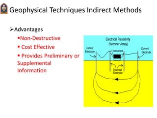
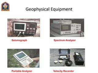
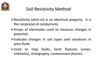
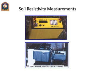
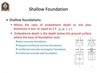
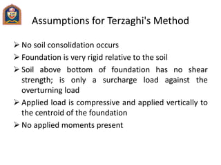
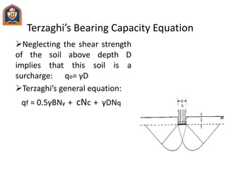
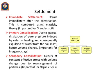
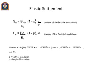
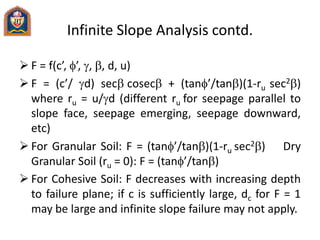
This document provides an overview of soils investigation and foundation design. It discusses the importance of soils investigation to evaluate subsurface conditions for construction projects. Various field and laboratory techniques are described for soils investigation, including test pits, boreholes, geophysical methods, and laboratory analysis. Factors influencing soil formation such as weathering and transportation are also covered. The document then discusses shallow foundation design, including bearing capacity theory, settlement analysis, and selection of appropriate foundation types based on subsurface conditions. Specific foundation types like spread footings, raft foundations, and their analysis are summarized.
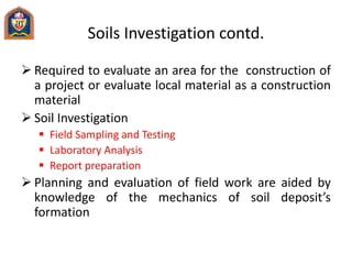
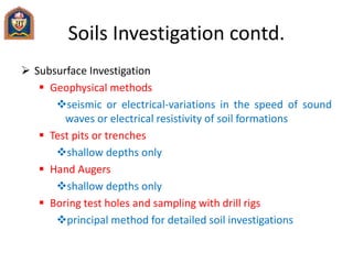
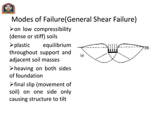
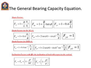
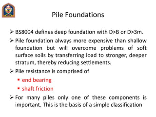
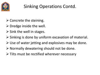
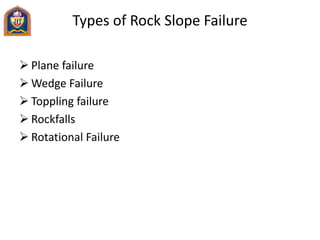
![Elastic Settlement [Schmertman Method
(1978)]
𝜌 = ∁1∁2∆𝜎
𝑖=1
𝑛
𝐼𝑧
𝐸
𝑖 ∆𝑍𝑖](https://image.slidesharecdn.com/advancedfoundationdesignnce-011-161230151922/85/Advanced-foundation-design-nce-011-45-320.jpg)
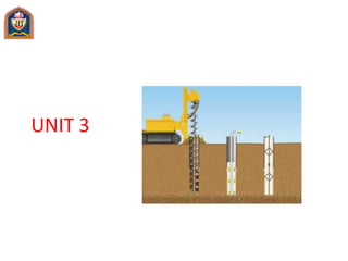
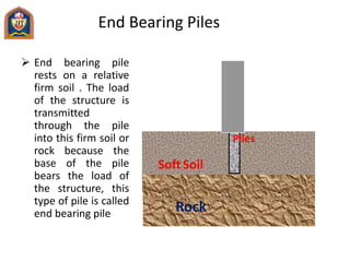


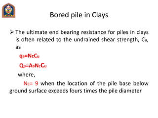
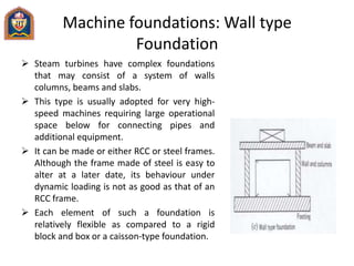
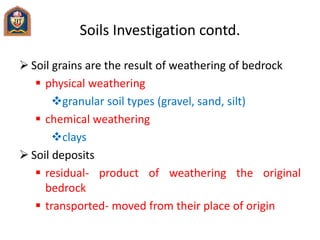
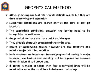
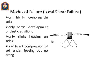
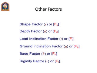
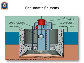
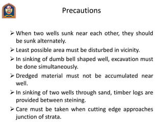
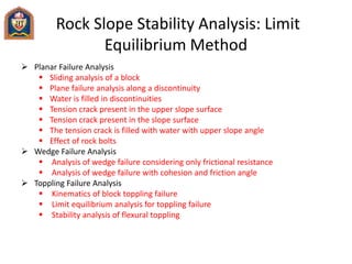
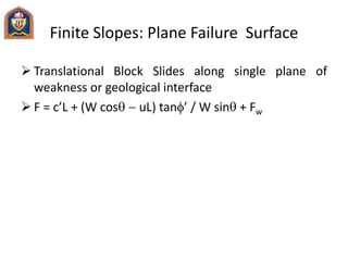
![Settlement of pile group
Block failure of pile groups is generally only a design
consideration for pile groups in soft cohesive soils or
in cohesionless soils underlain by a weak cohesive
layer.
The bearing capacity factor, Nc, for a rectangular pile
group is generally 9.
However, Nc should be calculated for pile groups
with small pile embedment depths and/or large
widths
Nc = 5 [ 1+D/5B ] [ 1+B/5Z ] ≤ 9](https://image.slidesharecdn.com/advancedfoundationdesignnce-011-161230151922/85/Advanced-foundation-design-nce-011-69-320.jpg)


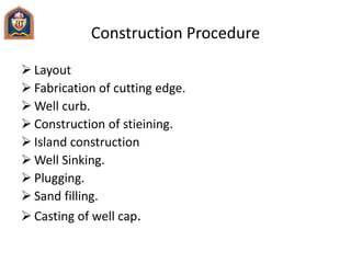
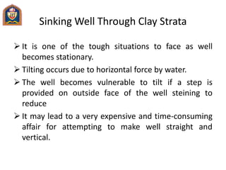

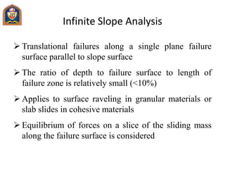
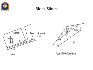
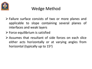
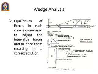
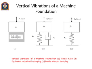
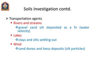
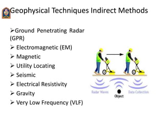
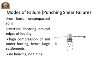
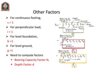
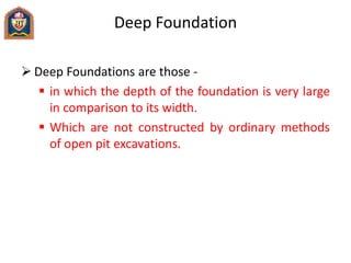
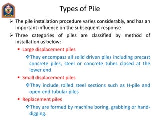
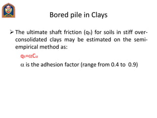
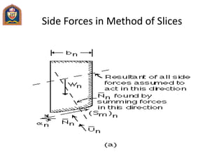
![Method of Slices
Assumes that resultant of side forces on each slice
are collinear and act parallel to failure surface and
therefore cancel each other
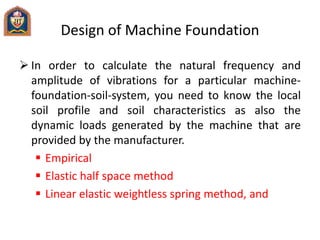
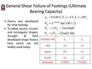
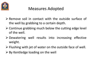
F = [cn ln + (Wn cosan - un ln) tann] / Wn sinan
Undrained analysis: F = [cn ln] / Wn sinan](https://image.slidesharecdn.com/advancedfoundationdesignnce-011-161230151922/85/Advanced-foundation-design-nce-011-110-320.jpg)
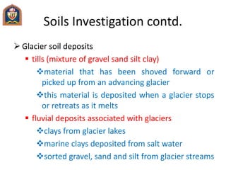
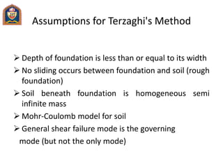
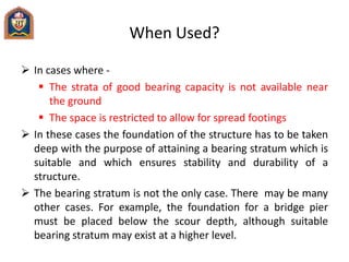
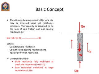
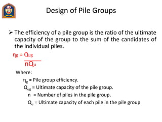
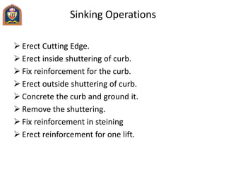
 / Wn sinan
ma = cosan + (sinan tanan)/F
Undrained analysis: F = [cn ln] / Wn sinan](https://image.slidesharecdn.com/advancedfoundationdesignnce-011-161230151922/85/Advanced-foundation-design-nce-011-112-320.jpg)