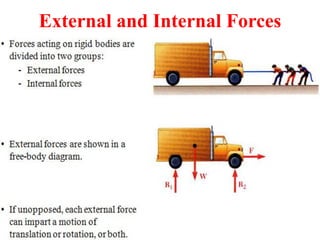
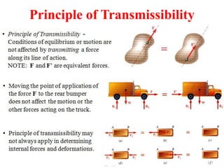
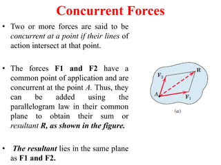
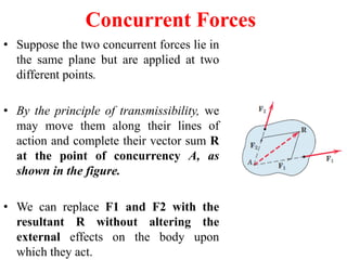
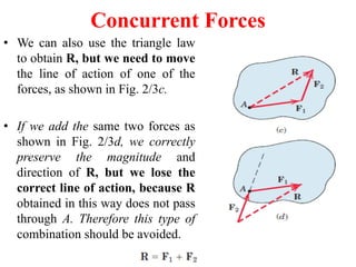
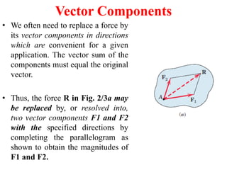
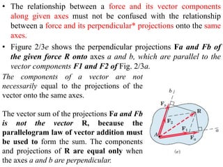
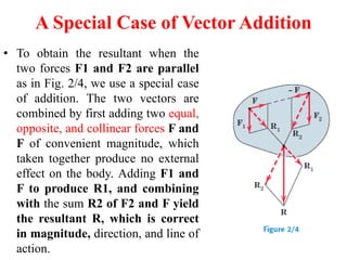
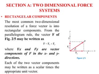
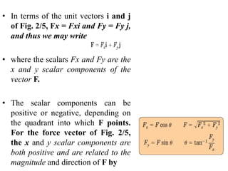
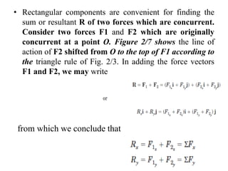
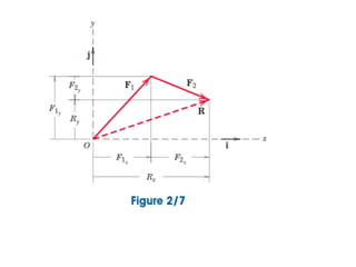
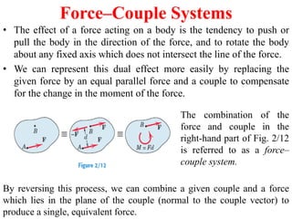
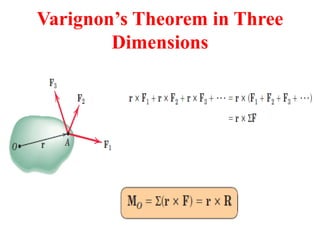
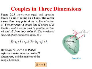
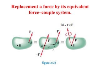
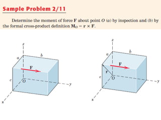
This document provides an overview of forces and force systems in engineering. It introduces the concept of a force vector and its components. Key points covered include:
- A force vector depends on both magnitude and direction. Most bodies are treated as rigid.
- Any system of forces on a rigid body can be replaced by a single force and couple. The principle of transmissibility allows treating forces as "sliding vectors".
- Forces are classified as contact or body forces, and as concentrated or distributed. Weight is treated as a concentrated force through the center of gravity.
- Methods for adding concurrent forces include the parallelogram and triangle laws. Forces can be resolved into rectangular components.
This document provides an overview of the content covered in the Basic Civil Engineering course. It discusses the following topics:
1. Mechanics of Rigid Bodies and Mechanics of Deformable Bodies, which make up Parts I and II of the course.
2. Concepts in mechanics of solids including resultant and equilibrium of coplanar forces, centroids, moments of inertia, kinetics principles, stresses and strains.
3. Five textbooks recommended as references for the course.
4. Definitions of terms like particle, force, scalar, vector, and rigid body.
5. Methods for resolving forces into components, obtaining the resultant of coplanar forces, and solving mechanics problems
This document provides an overview of the key concepts related to equilibrium of rigid bodies, including:
- Developing free-body diagrams to represent the forces acting on a rigid body and identify unknown support reactions.
- Using the equations of equilibrium (sum of forces equals zero in x and y directions, sum of moments equals zero) to solve for unknown forces and support reactions.
- Analyzing two-force and three-force members, as well as statically determinate and indeterminate structures.
Lecture slides on the calculation of the bending stress in case of unsymmetrical bending. The Mohr's circle is used to determine the principal second moments of area.
Lecture 1 Introduction to statics Engineering Mechanics hibbeler 14th editionaxmedbaasaay
This document discusses mechanics, specifically rigid body mechanics. It defines mechanics as dealing with forces and motion of bodies. Rigid body mechanics examines objects that do not deform under applied forces. This field is divided into statics, which considers motionless bodies, and dynamics, which examines moving bodies. Rigid body mechanics forms the basis for understanding deformable bodies and fluid mechanics. Key concepts introduced are particles, rigid bodies, forces, and Newton's laws of motion.
This document provides an overview of static equilibrium analysis for rigid bodies. It defines static equilibrium, introduces free-body diagrams, and describes how to write and solve equilibrium equations in two and three dimensions. Sample problems are included to demonstrate how to determine unknown reactions and forces by creating free-body diagrams, writing the appropriate equilibrium equations, and solving the system of equations. The document covers topics such as statically determinate and indeterminate systems, and how to analyze bodies subjected to two or three applied forces.
The document discusses the equilibrium of rigid bodies. It provides the following key points:
1) A rigid body is in equilibrium when the external forces acting on it combine to form a system equivalent to zero force and zero couple.
2) The necessary and sufficient conditions for equilibrium are that the net force F and net moment M must both equal zero.
3) To analyze equilibrium, a free-body diagram must be drawn showing all external forces acting on the body. Examples of equilibrium under single, two, and three forces are provided.
FEM: Introduction and Weighted Residual MethodsMohammad Tawfik
What are weighted residual methods?
How to apply Galerkin Method to the finite element model?
#WikiCourses #Num001
https://wikicourses.wikispaces.com/TopicX+Approximate+Methods+-+Weighted+Residual+Methods
The document describes several problems involving the calculation of normal stress and strain in structural elements like posts, rods, wires, and beams. The problems involve circular and rectangular cross-sections under compression, tension or a combination of forces. Diagrams are provided and the geometry, forces and material properties are used to calculate stress, strain or unknown forces through equilibrium equations. Solutions show the relevant equations and step-by-step workings to arrive at the final numerical answers.
The document discusses various topics related to stress and strain including: principal stresses and strains, Mohr's stress circle theory of failure, 3D stress and strain, equilibrium equations, and impact loading. It provides examples of stresses acting in different planes including normal, shear, oblique, and principal planes. It also gives examples of calculating normal and tangential stresses on an oblique plane subjected to stresses in one, two, or multiple directions with and without shear stresses.
The document discusses systems of forces acting on a body. It defines different types of force systems including coplanar forces that act in the same plane, and non-coplanar forces whose lines of action are not in the same plane. Within these categories, forces can be further classified as collinear if they act along the same line, concurrent if they intersect at a single point, parallel if their lines of action are parallel, and like or unlike based on direction. Examples are provided of different force system configurations such as concurrent coplanar forces intersecting in a plane, and non-concurrent non-coplanar forces that do not intersect and act in different planes.
Shear Force and Bending Moment DiagramsVishu Sharma
Short notes for shear force and bending moment diagrams in Strength Of materials for design calculation
Reference- Shigley’s Mechanical Engineering Design
moments couples and force couple systems by ahmad khanSelf-employed
To determine the resultant force acting at the top of the tower (point D), I would:
1. Resolve each cable force into its x and y components.
2. Use the parallelogram law of forces to combine the x-components of each cable force into a single x-component force. Do the same for the y-components.
3. The x and y component forces obtained from step 2 are the x and y components of the resultant force acting at D.
4. Use the Pythagorean theorem to determine the magnitude of the resultant force from its x and y components.
5. Use trigonometry to determine the direction of the resultant force relative to the x-axis
Lecture 9 shear force and bending moment in beamsDeepak Agarwal
The document discusses stresses in beams. It covers topics like shear force and bending moment diagrams, bending stresses, shear stresses, deflection, and torsion. Beams are structural members subjected to transverse forces that induce bending. Stresses and strains are created within beams when loaded. Shear forces and bending moments allow determining these internal stresses and maintaining equilibrium. Formulas are provided for calculating shear forces and bending moments in different beam configurations like cantilevers, simply supported beams, and beams with various load types.
Problems on simply supported beams (udl , uvl and couple)sushma chinta
1) A simply supported beam is subjected to a uniformly distributed load (UDL) over part of its span and a couple moment at one end.
2) Shear force and bending moment diagrams are drawn by dividing the beam into sections and analyzing each section.
3) The maximum bending moment occurs where the shear force is zero and is calculated to be 3761.59 N-m located at 2.637 m from the left support.
This document provides an overview of engineering mechanics statics. It covers topics including:
- Defining mechanics as the science dealing with bodies at rest or in motion under forces.
- Dividing mechanics into statics, dynamics, and other subfields. Statics deals with bodies at rest.
- Introducing fundamental concepts of forces, units of measurement, and representing forces as vectors that add according to the parallelogram law.
- Providing examples of adding forces graphically using the parallelogram law and triangle rule to determine the resultant force.
- Discussing problems involving determining the magnitude and direction of resultant forces from multiple forces acting on structures, stakes, and brackets
Learn Online Courses of Subject Engineering Mechanics of First Year Engineering. Clear the Concepts of Engineering Mechanics Through Video Lectures and PDF Notes. Visit us: https://ekeeda.com/streamdetails/subject/Engineering-Mechanics
Structural analysis (method of sections)physics101
The method of sections can be used to determine member forces in a truss. It involves cutting or sectioning the truss and applying equilibrium equations to the cut parts. For example, a truss can be cut through members to determine the forces in those members by drawing and analyzing the free-body diagram of each cut section. Either the method of joints or method of sections can be used to analyze trusses.
The document discusses the differences between centroid and center of gravity. The centroid is defined as a point about which the entire line, area or volume is assumed to be concentrated, and is related to the distribution of length, area and volume. The center of gravity is defined as the point about which the entire weight of an object is assumed to be concentrated, also known as the center of mass, and is related to the distribution of mass. Examples are provided to illustrate the concepts of centroid and center of gravity.
The document provides an overview of applied mechanics, including definitions of mechanics, engineering, applied mechanics, and their various branches and topics. It also covers fundamental concepts such as units, scalars, vectors, and trigonometry functions that are important to mechanics. Examples of static force analysis using vector operations like resolution and resultant are presented.
Principle of virtual work and unit load methodMahdi Damghani
The document summarizes the principle of virtual work (PVW) which is a fundamental tool in analytical mechanics. It defines virtual work as the work done by a real force moving through an arbitrary virtual displacement. The PVW states that if a particle is in equilibrium, the total virtual work done by the applied forces equals zero. Examples are provided to demonstrate how PVW can be used to determine unknown internal forces and slopes by equating the virtual work of external and internal forces.
The document discusses internal forces in structural members and how to determine them using the method of sections. It outlines how to draw free body diagrams of structural members, determine support reactions, and use equilibrium equations to calculate shear forces and bending moments. Sample problems are worked through step-by-step to demonstrate how to analyze beams and shafts and draw the corresponding shear and moment diagrams.
The document discusses non-concurrent forces and how to find their resultant. It defines non-concurrent forces as those whose lines of action do not meet at a single point. It provides examples of such forces, like those on a ladder leaning against a wall. The document discusses using graphical and algebraic methods to resolve non-parallel, non-concurrent forces into components. It also addresses calculating the total moment of such force systems to find the resultant force and its location.
The document discusses analysis methods for trusses, frames, and machines. Trusses consist of two-force members and can be analyzed using the method of joints or method of sections. The method of joints uses particle equilibrium at joints to solve for forces. The method of sections uses rigid body equilibrium to solve for forces by cutting the truss into sections. Frames contain multi-force members and can be analyzed by drawing free body diagrams of individual members and applying equilibrium equations. Machines contain multi-force members and are analyzed similarly to frames.
The document discusses trusses and their analysis using the method of joints. It defines a truss as an assembly of straight members connected at joints, with no member continuous through a joint. Trusses are made of pinned or bolted connections. Loads must be applied at the joints. The method of joints involves taking equilibrium at each joint to solve for member forces. Special cases like zero-force members under certain loadings are also discussed. The document also introduces the method of sections to determine forces in selected members.
Chapter 2: Two dimenstional force systems: DBU-MESAYitagesu Ethiopia
This document outlines force systems, including two-dimensional (2D) and three-dimensional (3D) force systems. It discusses 2D force resolution into rectangular components using the parallelogram rule. Examples show resolving forces into x and y scalar components using unit vectors. Exercises provide practice calculating resultant forces and moments, including moments about a point and combined moments. Couples are also introduced, along with examples of replacing force systems with equivalent couples and resultants.
The document discusses static force analysis in machines. It defines static forces as those transmitted by machine members without accounting for acceleration. Static force analysis determines the forces acting on machine members at a particular configuration, assuming the members are rigid bodies in static equilibrium under external forces. This analysis is a starting point for strength design and avoids over or under estimation of forces. Equilibrium conditions for members with two or three forces are described, including the need for concurrent lines of action and zero resultant force. Examples analyze forces in four-force members and determine unknown force magnitudes through force diagrams.
Force is defined as any interaction that, when unopposed, will change the motion of an object. It is a vector quantity that has both magnitude and direction. The parallelogram law of forces states that the resultant of two concurrent forces can be determined by drawing them as the sides of a parallelogram, with the resultant being the diagonal of the parallelogram. Wood has varying mechanical properties depending on whether force is applied parallel or perpendicular to the wood grain, with strength greatest in compression parallel to grain and least in tension perpendicular to grain. Properties like modulus of elasticity also determine a wood member's resistance to bending and deformation.
Mechanics is the physical science concerned with the behavior of bodies acted upon by forces. It has two main branches: statics, which deals with bodies at rest or in equilibrium, and dynamics, which deals with bodies in motion. Dynamics is divided into kinematics, which considers motion without forces, and kinetics, which considers motion with forces. Mechanics studies rigid and deformable bodies, as well as fluids. Forces can be analyzed using concepts such as components, resultants, and force systems.
coplanar forces res comp of forces - for mergeEkeeda
Learn Online Courses of Subject Engineering Mechanics of First Year Engineering. Clear the Concepts of Engineering Mechanics Through Video Lectures and PDF Notes. Visi tus: https://ekeeda.com/streamdetails/subject/Engineering-Mechanics
Coplanar forces res & comp of forces - for mergeEkeeda
Ekeeda Provides Online Video Lectures for Civil Engineering Degree Subject Courses for All Engineering Universities. Visit us: https://ekeeda.com/streamdetails/stream/civil-engineering
Ekeeda Provides Online Civil Engineering Degree Subjects Courses, Video Lectures for All Engineering Universities. Video Tutorials Covers Subjects of Mechanical Engineering Degree.
Learn Online Courses of Subject Engineering Mechanics of First Year Engineering. Clear the Concepts of Engineering Mechanics Through Video Lectures and PDF Notes. Visit us: https://ekeeda.com/streamdetails/subject/Engineering-Mechanics
This document outlines the course CM 154 Statics of Rigid Bodies taught by Dr. Kofi Agyekum. It will cover topics related to engineering mechanics including types of force systems, resolution of forces, and determining the resultant of concurrent coplanar forces using various methods like the triangle law and parallelogram law. Students will learn to analyze rigid bodies that are either at rest or in static equilibrium by applying the principles of static equilibrium. Recommended textbooks are also listed.
1. The document discusses the analysis of forces and torques acting on mechanisms and machines. It covers topics like static force analysis, equilibrium of two and three force members, and determination of reaction forces and torques.
2. Key concepts discussed include Newton's laws of motion, types of common forces like applied, reaction and friction forces, and the use of free body diagrams and vector methods to analyze mechanisms.
3. The goal of force analysis is to determine the forces transmitted through a machine to enable proper strength design of components. Both graphical and analytical methods are described.
General system of forces unit 4 bce & engg mechanicsParimal Jha
The document discusses general systems of forces in engineering mechanics. It covers equations of equilibrium for concurrent coplanar forces in a plane, types of support and reaction forces, and free body diagrams. Free body diagrams show all external forces acting on a body and are used to analyze equilibrium of forces on objects. Key concepts covered include concurrent and non-concurrent forces, constraints, actions and reactions, and the moment of a force.
Force analysis is a fundamental tool used to understand how forces affect the motion and behavior of objects. It involves identifying all forces acting on an object, determining their magnitudes and directions, and applying Newton's laws of motion. Force analysis is used across various engineering fields to predict how structures and systems will perform under different loading conditions. It allows engineers to design structures and machines that can withstand anticipated forces safely and efficiently. Force analysis considers both static systems at rest as well as dynamic systems in motion. Computer modeling has enhanced force analysis by enabling complex systems to be simulated.
This document provides information about moments of forces from a textbook on vector mechanics for engineers. It defines the moment of a force about a point and describes how to find the moment vector. It also discusses couples, which are two forces of equal magnitude and opposite direction, and how to calculate the moment of a couple. The document explains how to resolve a force into equivalent force and couple components at a given point using vector algebra. It provides examples of calculating the equivalent force and couple for systems of forces.
The document discusses determining internal forces in structural members using statics. It provides objectives of showing how to use the method of sections to find internal loadings and formulate equations to describe shear and moment throughout a member. Key steps are outlined, including making a section cut, drawing a free body diagram, and applying equilibrium equations to solve for the normal force, shear force and bending moment. Sign conventions are also defined. Shear and moment diagrams are then explained as plots of these internal forces along the length of a beam, with examples provided to demonstrate the full procedure.
This document provides an overview of biomechanics concepts related to orthodontic tooth movement. It discusses key concepts such as forces, vector addition and resolution, centers of resistance and rotation, and types of tooth movement. The document is intended to explain the physical principles underlying orthodontic mechanics to optimize force systems and tooth responses in treatment.
In physics, a force is any interaction which tends to change the motion of an object.
In other words, a force can cause an object with mass to change its velocity (which includes to begin moving from a state of rest), i.e., to accelerate.
Force can also be described by intuitive concepts such as a push or a pull.
A force has both magnitude and direction, making it a vector quantity. It is measured in the SI unit of newtons and represented by the symbol F.
The original form of Newton's second law states that the net force acting upon an object is equal to the rate at which its momentum changes with time.
If the mass of the object is constant, this law implies that the acceleration of an object is directly proportional to the net force acting on the object, is in the direction of the net force, and is inversely proportional to the mass of the object.
As a formula, this is expressed as:
Related concepts to force include: thrust, which increases the velocity of an object; drag, which decreases the velocity of an object; and torque which produces changes in rotational speed of an object. In an extended body, each part usually applies forces on the adjacent parts; the distribution of such forces through the body is the so-called mechanical stress.
Pressure is a simple type of stress. Stress usually causes deformation of solid materials, or flow in fluids.
Aristotle famously described a force
Static force analysis examines forces on structures when inertia forces are negligible compared to external forces. The document defines types of forces like tension, compression, and shear. It also discusses Newton's laws of motion, equilibrium conditions for 2-force and 3-force systems, and constructing free body diagrams to isolate individual parts. Moment of inertia and inertia forces are introduced, along with applying principles like D'Alembert's to dynamic force analysis when inertia forces are significant.
This document discusses statics concepts including forces, laws of forces, resolution of forces, moments and couples of forces, and conditions for equilibrium. It provides examples and problems involving determining resultant forces, reactions, and friction forces for systems in equilibrium, including ladders, beams with hanging masses, and objects on inclined planes. Key concepts covered are the parallelogram law, triangle law, Lami's theorem, and conditions that forces and moments must balance for a body to be in equilibrium.
This document discusses basic principles of statics, which is the branch of mechanics dealing with stationary bodies under forces. It defines static equilibrium as when the sum of all forces and moments equals zero. It also discusses concepts such as static determinacy, types of forces including vectors and their addition, resolution of forces, concurrent forces, and free-body diagrams. Examples are provided to demonstrate how to determine reactions and tensions using these principles.
Unit 1-staticforceanalysis of slider crank and four bar mechanismMatam Prasad
1. The document discusses static force analysis and equilibrium of mechanical systems. It covers topics like static equilibrium, equilibrium of two and three force members, members with two forces and torque, and free body diagrams.
2. It provides explanations and examples of analyzing static equilibrium for mechanical components like links in mechanisms. The principles of static equilibrium - zero net force and zero net moment - are explained.
3. Methods for analyzing equilibrium of members with different numbers of forces and/or torques are presented, including using free body diagrams and force triangles to determine unknown force magnitudes and directions.
Unit 1-staticforceanalysis of slider crank and four bar mechanismMatam Prasad
1. The document discusses static force analysis and equilibrium of mechanical systems. It covers topics like static equilibrium, two and three force members, free body diagrams, and the principle of virtual work.
2. Methods for analyzing static equilibrium in systems with two forces, three forces, two forces and a torque are presented. Key concepts like collinear forces and concurrent lines of action are discussed.
3. Examples of applying these methods to analyze static equilibrium in four-bar mechanisms and slider-crank mechanisms are provided. Free body diagrams are drawn and force polygons are used to determine unknown forces.
Similar to engineering statics :force systems (20)
The design of Farm cart 0011 report 1 2020musadoto
This report describes the best designing of a 200cc FARM CART MACHINE which will be useful to the farm fields due to the fact that, the purchase, repair and maintenance are affordable to all level of income earners. Despite the cost effectiveness of the machine, the report also tries to justify that the machine can be used multipurposely as it serves the purposes of been used as farm transport, mowering machine, boom spraying and or mini planter with two rows. All these can be achieved as long as the implements are attached with respect to the power capacity of the farm cart.
The report tells only the design and testing of machine excluding its farm implements design. Some best reviews from other study projects done by other people in the world provided a good reference for designing and implementation of this project. The project is initially costly because it needs to develop a prototype and test the different first ideas.
The project report describes the important of choosing to use the designed farm cart machine compared to other farm machines at the market which are most efficiently to be used by farmers in their fields.
The challenges are inevitable in any project, here in designing of this 200cc farm machine, the major issue is the funding because the fund for this project is from the pocket which is always insufficient as it depends to the meals and accommodation money distribution sponsored from the HIGH EDUCATION STUDENTS LOAN BOARD (HESLB) thus it takes longer to accomplish the project by waiting another quarter of the semester to continue with the project which affects the other part of normal life(in terms of meals and accommodation).
The report recommends that, the department of engineering sciences and technology and Sokoine University of Agriculture as a whole should invest into this technology by utilizing fully the idea and funding the project for more better improvement so as to attain the desired standard that can with stand the different farm field factors. These when taken into consideration there is a possibility to achieve the industrialization policy in our country and thereafter it is a better approach to modern agriculture.
IRRIGATION SYSTEMS AND DESIGN - IWRE 317 questions collection 1997 - 2018 ...musadoto
This document contains sample exam questions for a course on irrigation systems design. It includes multiple choice and short answer questions testing understanding of key irrigation concepts. Some example questions are on pump characteristics, calculating water requirements for drip and sprinkler systems, estimating consumptive water use, and determining system efficiencies. The document provides a compilation of past exam questions from 1997 to 2018 to help students prepare for tests.
CONSTRUCTION [soil treatment, foundation backfill, Damp Proof Membrane[DPM] a...musadoto
With reference to a construction site visited recently, describe in details key features
that can be observed on site as follows
Foundations backfilling, hardcore, soil treatment, DPM and BRC works prior
to pouring oversite concrete
CONSTRUCTION [soil treatment, foundation backfill, Damp Proof Membrane[DPM] and BRC for engineers (civil)
BASICS OF COMPUTER PROGRAMMING-TAKE HOME ASSIGNMENT 2018musadoto
Self- Check 1
Which of the following are Pascal reserved words, standard identifiers, valid identifiers, invalid identifiers?
end ReadLn Bill
program Sues‟s Rate
Start begin const
Y=Z Prog#2 &Up
First Name „MaxScores‟ A*B
CostaMesa,CA Barnes&Noble CONST
XYZ123 ThisIsALongOne 123XYZANSWER
ANSWERS
Paschal reserved words:
begin, end, program, Start, CONST, const
Standard identifiers:
ReadLn, „MaxScores‟, Bill, Rate
Valid identifiers:
XYZ123, ThisIsALongOne, A*B, Y=Z, CostaMesa, CA, First Name
Invalid identifiers:
123XYZ, Sues‟s, &UpFirstName, Barnes&Noble, Prog#2
Self- Check 2
Which of the following literal values are legal and what are their types? Which are illegal and why?
15 „XYZ‟ „*‟
$25.123 15; -999
.123 „x‟ “X”
„9‟ „-5‟ True
ANSWER:
The following values are legal and their type
Legal
Type
Illegal
15
Integer literal
$25.123
„XYZ‟
String Literal
.123
„X‟
Character Literal
„9‟
True
Boolean Literal
15;
-999
Integer Literal
-„5‟
Operator literal
„*‟
TP- Lecture 4.2
Self- Checked 1
Which of the following are valid program headings? Which are invalid and why?
(i) Program program; - INVALID using reserved ID
(ii) program 2ndCourseInCS; -INVALID because starts with digit
(iii) program PascalIsFun;- VALID program heading
(iv) program Rainy Day; -INVALID – contains space
Self- Checked 2
Rewrite the following code so that it has no syntax errors and follows the writing conventions we adopted
(i) Program SMALL;
VAR X, Y, Z : real;
BEGIN
Y := 15.0;
Z := -Y + 3.5;
X :=Y + z;
writeln (x, Y, z);
END.
ANSWER:
Program
ENGINEERING SYSTEM DYNAMICS-TAKE HOME ASSIGNMENT 2018musadoto
1. Read Chapter 4 – System Dynamics for Mechanical Engineers by Matthew Davies and Tony L. Schmitz and implement Examples 4.1 to 4.12 in Matlab.
2. Read Chapter 7 – System Dynamics for Mechanical Engineers by Matthew Davies and Tony L. Schmitz and implement Examples 7.1 to 7.11 in Matlab.
3. Read Chapter 9 – System Dynamics for Mechanical Engineers by Matthew Davies and Tony L. Schmitz and implement Examples 9.1 to 9.6 in Matlab.
4. Read Chapter 11 – System Dynamics for Mechanical Engineers by Matthew Davies and Tony L. Schmitz and implement Examples 11.1 to 11.7 in Matlab.
5. Read Chapter 2 - System Dynamics for Engineering Students: Concepts and Applications by Nicolae Lobontiu and attempt problem 2.18 (page 63).
6. Read Chapter 3 - System Dynamics for Engineering Students: Concepts and Applications by Nicolae Lobontiu and attempt problem 3.13 (pp 98 - 100).
7. Read Chapter 4 - System Dynamics for Engineering Students: Concepts and Applications by Nicolae Lobontiu and attempt problem 4.20 (page 146).
8. Read Chapter 5 - System Dynamics for Engineering Students: Concepts and Applications by Nicolae Lobontiu and attempt problems 5.15 (page 198), 5.21 (pp 199 - 200) and 5.27 (pp 201 – 202).
Hardeninig of steel (Jominy test)-CoET- udsmmusadoto
The document describes a Jominy end-quench test experiment to measure the hardenability of two steel samples. Steel samples A and C were heated to the austenite temperature and quenched with water at one end. Hardness measurements using the Rockwell C scale were taken at intervals along the samples. Sample A showed little variation in hardness, while hardness decreased with distance from the quenched end for sample C. A graph of hardness versus distance revealed that sample A has higher hardenability, retaining hardness further from the quenched end. The hardenability indices at 50HRC were determined to be 2mm, 5mm, and 6.5mm from the graph.
1.1 The aim of the experiment
The aim of the experiment is to test the usefulness of the ultrasonic waves, by passing them through different
solids one can find out a lot of physical properties like young’s modulus , defects, Poisson ratio, Velocity of
sound in respective material this is due to the response of the received ultrasonic waves.
1.2 Theory of experiment
Ultrasonic testing (UT) is a family of non-destructive testing (NDT) techniques based on the propagation of ultrasonic waves in the object or material tested. In most common UT applications, very short ultrasonic pulse-waves with center frequencies ranging from 0.1-15 MHz, and occasionally up to 50 MHz, are transmitted into materials to detect internal flaws or to characterize materials. A common example is ultrasonic thickness measurement, which tests the thickness of the test object, for example, to monitor pipework corrosion.
Ultrasonic testing is often performed on steel and other metals and alloys, though it can also be used on concrete, wood and composites, albeit with less resolution. It is used in many industries including steel and aluminium construction, metallurgy, manufacturing, aerospace, automotive and other transportation sectors.
Ae 219 - BASICS OF PASCHAL PROGRAMMING-2017 test manual solutionmusadoto
Whether the Pascal program is small or large, it must have a specific structure. This
program consists mainly of one statement (WRITELN) which does the actual work
here, as it displays whatever comes between the parentheses. The statement is
included inside a frame starting with the keyword BEGIN and ending with the keyword
END. This is called the program main body (or the program block) and usually
contains the main logic of data processing.
1. The background of Fluid Mechanics
2. Fields of Fluid mechanics
3. Introduction and Basic concepts
4. Properties of Fluids
5. Pressure and fluid statics
6. Hydrodynamics
Fluid mechanics (a letter to a friend) part 1 ...musadoto
1. The background of Fluid Mechanics
2. Fields of Fluid mechanics
3. Introduction and Basic concepts
4. Properties of Fluids
5. Pressure and fluid statics
6. Hydrodynamics
Fluids mechanics (a letter to a friend) part 1 ...musadoto
1. The background of Fluid Mechanics
2. Fields of Fluid mechanics
3. Introduction and Basic concepts
4. Properties of Fluids
5. Pressure and fluid statics
6. Hydrodynamics
Fresh concrete -building materials for engineersmusadoto
CONCRETE
is a building Material made from a mixture of gravel ,sand ,cement,water and air ,forming a stone like mass on hardenning.
FRESH CONCRETE
It is a concrete that has not reached the final setting time.
Course Contents:
Introduction; Linear measurements; Analysis and adjustment of measurements, Survey methods: coordinate systems, bearings, horizontal control, traversing, triangulation, detail surveying; Orientation and position; Areas and volumes; Setting out; Curve ranging; Global Positioning system (GPS); Photogrammetry.
Fresh concrete -building materials for engineersmusadoto
General introduction
CONCRETE
is a building Material made from a mixture of gravel ,sand ,cement,water and air ,forming a stone like mass on hardenning.
FRESH CONCRETE
It is a concrete that has not reached the final setting time.
DIESEL ENGINE POWER REPORT -AE 215 -SOURCES OF FARM POWERmusadoto
The diesel engine (also known as a compression-ignition or CI engine), named after Rudolf Diesel, is an internal combustion engine in which ignition of the fuel which is injected into the combustion chamber is caused by the elevated temperature of the air in the cylinder due to mechanical compression (adiabatic compression). Diesel engines work by compressing only the air. This increases the air temperature inside the cylinder to such a high degree that atomised diesel fuel that is injected into the combustion chamber ignites spontaneously. This contrasts with spark-ignition engines such as a petrol engine (gasoline engine) or gas engine (using a gaseous fuel as opposed to petrol), which use a spark plug to ignite an air-fuel mixture. In diesel engines, glow plugs (combustion chamber pre-warmers) may be used to aid starting in cold weather, or when the engine uses a lower compression-ratio, or both. The original diesel engine operates on the "constant pressure" cycle of gradual combustion and produces no audible knock.
A diesel engine built by MAN AG in 1906
Detroit Diesel timing
Fairbanks Morse model 32
The diesel engine has the highest thermal efficiency (engine efficiency) of any practical internal or external combustion engine due to its very high expansion ratio and inherent lean burn which enables heat dissipation by the excess air. A small efficiency loss is also avoided compared to two-stroke non-direct-injection gasoline engines since unburned fuel is not present at valve overlap and therefore no fuel goes directly from the intake/injection to the exhaust. Low-speed diesel engines (as used in ships and other applications where overall engine weight is relatively unimportant) can have a thermal efficiency that exceeds 50%.[1][2
Farm and human power REPORT - AE 215-SOURCES OF FARM POWER musadoto
Farm is an area of land and its building, used for growing crops a rearing of animals or an area of land
that is devoted primarily of agricultural process with the primary objective of producing food and other
commercial crops. Or an area of water that is devoted primarily to agricultural process in order to
produce and manage such commodities as fibers, grains, livestock or fuel.
The process of working the ground, planting seeds and growing of planting known as farming.it can
described s raising of animals for milk and meat as farming.
ENGINE POWER PETROL REPORT-AE 215-SOURCES OF FARM POWERmusadoto
What is an Engine?
Before knowing about how the Petrol Engine works, let's first understand what an engine is. This is common for both petrol and diesel engines alike. An engine is a power generating machine which converts potential energy of the fuel into heat energy and then into motion. It produces power and also runs on its own power.
The engine generates its power by burning the fuel in a self-regulated and controlled „Combustion‟ process. The combustion process involves many sub-processes which burn the fuel efficiently and results in the smooth running of the engine.
These processes include:
The suction of air (also known as breathing or aspiration).
Mixing of the fuel with air after breaking the liquid fuel into highly atomized / mist form.
Igniting the air-fuel mixture with a spark (petrol engine).
Burning of highly atomized fuel particles which results in releasing / ejection of heat energy.
How does an Engine work?
The engine converts Heat Energy into Kinetic Energy in the form of „Reciprocating Motion‟. The expansion of heated gases and their forces act on the engine pistons. The gases push the pistons downwards which results in reciprocating motion of pistons.
This motion of the piston enables the crank-shaft to rotate. Thus, it finally converts the reciprocating motion into the 'Rotary motion' and passes on to wheels.
A petrol engine (known as a gasoline engine in American English) is an internal combustion engine with spark-ignition, designed to run on petrol (gasoline) and similar volatile fuels.
In most petrol engines, the fuel and air are usually mixed after compression (although some modern petrol engines now use cylinder-direct petrol injection). The pre-mixing was formerly done in a carburetor, but now it is done by electronically controlled fuel injection, except in small engines where the cost/complication of electronics does not justify the added engine efficiency. The process differs from a diesel engine in the method of mixing the fuel and air, and in using spark plugs to initiate the combustion process. In a diesel engine, only air is compressed
TRACTOR POWER REPORT -AE 215 SOURCES OF FARM POWER 2018musadoto
A tractor is an engineering vehicle specifically designed to deliver a high tractive effort (or torque) at slow speeds, for the purposes of hauling a trailer or machinery used in agriculture or construction. Most commonly, the term is used to describe a farm vehicle that provides the power and traction to mechanize agricultural tasks, especially (and originally) tillage, but nowadays a great variety of tasks. Agricultural implements 0may be towed behind or mounted on the tractor, and the tractor may also provide a source of power if the implement is mechanised.
The word Tractor is derived prior to 1900, the Machine were known as traction motor (pulling-machine).After the year 1900 both the words are joined by taking ‘Tract’ from Traction and ‘Tor” from motor calling it a Tractor.
In our Country tractors were started manufacturing in real sense after independence and at present we are self-sufficient in meeting demand of country’s requirement for tractors. Our country is basically an agricultural country where 75% of our population is directly or indirectly connected with agriculture. This cannot be produced with our conventional bullock pulled agricultural implements. Tractor is one of the basic agricultural machines
used for speeding up agriculture production.
WIND ENERGY REPORT AE 215- 2018 SOURCES OF FARM POWERmusadoto
Wind is the flow of gases on large scale. On the surface of the earth, wind consists of the bulk movement of air. In outer space, solar wind is the movement of gases and charged particles from the sun though space, while planetary wind is the outgassing of light chemical from a planet’s atmosphere into space. Wind by their spatial scale, their speed, the type of force that cause them, the region in which they occur and their effect. The strongest observed winds on planet in solar system occur on Neptune and Saturn. Winds have various aspects, an important one being its velocity, density of the gas involved and energy content of the wind.
Wind is almost entirely caused by the effects of the sun which, each hour, delivers 175 million watts of energy to the earth. This energy heats the planet’s surface, most intensively at the equator, which causes air to rise. This rising air creates an area of low pressure at the surface into which cooler air is sucked, and it is this flow of air that we know as “wind”. In reality atmospheric circulation is much more complicated and, after rising at the equator air travels pole wards. As it travels the air cools and eventually descends to the earth’s surface at about 30° latitude (north and south), from where it returns once again to the equator (a closed loop known as a Hadley Cell). Similar cells exist between 30° and 60° latitude (the Ferrell Cells) and between 60° latitude and each of the poles (the Polar Cells). Within these cells, the flow of air is further impacted by the rotation of the earth or the "Coriolis Effect". This effect creates a sideways force which causes air to circulate anticlockwise around areas of low pressure in the northern hemisphere and clockwise in the southern hemisphere
In summary, the origin of winds may be traced basically to uneven heating of the earth’s surface due to sun. This may lead to circulation of widespread winds on a global basis, producing planetary winds or may have a limited influence in a smaller area to cause local winds.
How to Manage Reception Report in Odoo 17Celine George
A business may deal with both sales and purchases occasionally. They buy things from vendors and then sell them to their customers. Such dealings can be confusing at times. Because multiple clients may inquire about the same product at the same time, after purchasing those products, customers must be assigned to them. Odoo has a tool called Reception Report that can be used to complete this assignment. By enabling this, a reception report comes automatically after confirming a receipt, from which we can assign products to orders.
Philippine Edukasyong Pantahanan at Pangkabuhayan (EPP) CurriculumMJDuyan
(𝐓𝐋𝐄 𝟏𝟎𝟎) (𝐋𝐞𝐬𝐬𝐨𝐧 𝟏)-𝐏𝐫𝐞𝐥𝐢𝐦𝐬
𝐃𝐢𝐬𝐜𝐮𝐬𝐬 𝐭𝐡𝐞 𝐄𝐏𝐏 𝐂𝐮𝐫𝐫𝐢𝐜𝐮𝐥𝐮𝐦 𝐢𝐧 𝐭𝐡𝐞 𝐏𝐡𝐢𝐥𝐢𝐩𝐩𝐢𝐧𝐞𝐬:
- Understand the goals and objectives of the Edukasyong Pantahanan at Pangkabuhayan (EPP) curriculum, recognizing its importance in fostering practical life skills and values among students. Students will also be able to identify the key components and subjects covered, such as agriculture, home economics, industrial arts, and information and communication technology.
𝐄𝐱𝐩𝐥𝐚𝐢𝐧 𝐭𝐡𝐞 𝐍𝐚𝐭𝐮𝐫𝐞 𝐚𝐧𝐝 𝐒𝐜𝐨𝐩𝐞 𝐨𝐟 𝐚𝐧 𝐄𝐧𝐭𝐫𝐞𝐩𝐫𝐞𝐧𝐞𝐮𝐫:
-Define entrepreneurship, distinguishing it from general business activities by emphasizing its focus on innovation, risk-taking, and value creation. Students will describe the characteristics and traits of successful entrepreneurs, including their roles and responsibilities, and discuss the broader economic and social impacts of entrepreneurial activities on both local and global scales.
This presentation was provided by Rebecca Benner, Ph.D., of the American Society of Anesthesiologists, for the second session of NISO's 2024 Training Series "DEIA in the Scholarly Landscape." Session Two: 'Expanding Pathways to Publishing Careers,' was held June 13, 2024.
This presentation was provided by Racquel Jemison, Ph.D., Christina MacLaughlin, Ph.D., and Paulomi Majumder. Ph.D., all of the American Chemical Society, for the second session of NISO's 2024 Training Series "DEIA in the Scholarly Landscape." Session Two: 'Expanding Pathways to Publishing Careers,' was held June 13, 2024.
How Barcodes Can Be Leveraged Within Odoo 17Celine George
In this presentation, we will explore how barcodes can be leveraged within Odoo 17 to streamline our manufacturing processes. We will cover the configuration steps, how to utilize barcodes in different manufacturing scenarios, and the overall benefits of implementing this technology.
CapTechTalks Webinar Slides June 2024 Donovan Wright.pptxCapitolTechU
Slides from a Capitol Technology University webinar held June 20, 2024. The webinar featured Dr. Donovan Wright, presenting on the Department of Defense Digital Transformation.
Temple of Asclepius in Thrace. Excavation resultsKrassimira Luka
The temple and the sanctuary around were dedicated to Asklepios Zmidrenus. This name has been known since 1875 when an inscription dedicated to him was discovered in Rome. The inscription is dated in 227 AD and was left by soldiers originating from the city of Philippopolis (modern Plovdiv).
2. Introduction
In this and the following chapters, we study
the effects of forces which act on engineering
structures and mechanisms. The experience
gained here will help you in the study of
mechanics and in other subjects such as stress
analysis, design of structures and machines,
and fluid flow.
3. Force
A Force is a vector quantity, because its effect depends on
the direction as well as on the magnitude of the action.
Treatment of a body as a single particle is not always
possible. In general, the size of the body and the specific
points of application of the forces must be considered.
Most bodies in elementary mechanics are assumed to be
rigid, i.e., the actual deformations are small and do not
affect the conditions of equilibrium or motion of the body.
4. • Current chapter describes the effect of forces exerted on a
rigid body and how to replace a given system of forces with
a simpler equivalent system.
• moment of a force about a point
• moment of a force about an axis
• moment due to a couple
Any system of forces acting on a rigid body can be replaced
by an equivalent system consisting of one force acting at a
given point and one couple.
7. • The principle of transmissibility, states that a force may
be applied at any point on its given line of action without
altering the resultant effects of the force external to the
rigid body on which it acts.
• Thus, whenever we are interested in only the resultant
external effects of a force, the force may be treated as a
sliding vector, and we need specify only the magnitude,
direction, and line of action of the force, and not its point
of application.
• Since, we deal essentially with the mechanics of rigid
bodies, we will treat almost all forces as sliding vectors
for the rigid body on which they act.
8. Force Classification
• Forces are classified as either contact or body forces.
• A contact force is produced by direct physical contact; an
example is the force exerted on a body by a supporting
surface.
• A body force is generated by virtue of the position of a
body within a force field such as a gravitational, electric,
or magnetic field. An example of a body force is your
weight.
9. Force Classification
• Forces may be further classified as either concentrated or
distributed.
• Every contact force is actually applied over a finite area
and is therefore really a distributed force.
• However, when the dimensions of the area are very small
compared with the other dimensions of the body, we may
consider the force to be concentrated at a point with
negligible loss of accuracy. Force can be distributed over
an area, as in the case of mechanical contact, over a
volume when a body force such as weight is acting, or
over a line, as in the case of the weight of a suspended
cable.
10. Force Classification
• The weight of a body is the force of
gravitational attraction distributed over its
volume and may be taken as a concentrated
force acting through the center of gravity. The
position of the center of gravity is frequently
obvious if the body is symmetric. If the
position is not obvious, then a separate
calculation, explained in Chapter 5, will be
necessary to locate the center of gravity.
11. Concurrent Forces
• Two or more forces are said to be
concurrent at a point if their lines of
action intersect at that point.
• The forces F1 and F2 have a
common point of application and are
concurrent at the point A. Thus, they
can be added using the
parallelogram law in their common
plane to obtain their sum or
resultant R, as shown in the figure.
• The resultant lies in the same plane
as F1 and F2.
12. Concurrent Forces
• Suppose the two concurrent forces lie in
the same plane but are applied at two
different points.
• By the principle of transmissibility, we
may move them along their lines of
action and complete their vector sum R
at the point of concurrency A, as
shown in the figure.
• We can replace F1 and F2 with the
resultant R without altering the
external effects on the body upon
which they act.
13. Concurrent Forces
• We can also use the triangle law
to obtain R, but we need to move
the line of action of one of the
forces, as shown in Fig. 2/3c.
• If we add the same two forces as
shown in Fig. 2/3d, we correctly
preserve the magnitude and
direction of R, but we lose the
correct line of action, because R
obtained in this way does not pass
through A. Therefore this type of
combination should be avoided.
14. Vector Components
• We often need to replace a force by
its vector components in directions
which are convenient for a given
application. The vector sum of the
components must equal the original
vector.
• Thus, the force R in Fig. 2/3a may
be replaced by, or resolved into,
two vector components F1 and F2
with the specified directions by
completing the parallelogram as
shown to obtain the magnitudes of
F1 and F2.
15. • The relationship between a force and its vector components
along given axes must not be confused with the relationship
between a force and its perpendicular* projections onto the same
axes.
• Figure 2/3e shows the perpendicular projections Fa and Fb of
the given force R onto axes a and b, which are parallel to the
vector components F1 and F2 of Fig. 2/3a.
The components of a vector are not
necessarily equal to the projections of the
vector onto the same axes.
The vector sum of the projections Fa and Fb
is not the vector R, because the
parallelogram law of vector addition must
be used to form the sum. The components
and projections of R are equal only when
the axes a and b are perpendicular.
16. A Special Case of Vector Addition
• To obtain the resultant when the
two forces F1 and F2 are parallel
as in Fig. 2/4, we use a special case
of addition. The two vectors are
combined by first adding two equal,
opposite, and collinear forces F and
F of convenient magnitude, which
taken together produce no external
effect on the body. Adding F1 and
F to produce R1, and combining
with the sum R2 of F2 and F yield
the resultant R, which is correct
in magnitude, direction, and line of
action.
17. SECTION A: TWO DIMENSIONAL FORCE
SYSTEMS
• RECTANGULAR COMPONENTS
The most common two-dimensional
resolution of a force vector is into
rectangular components. From the
parallelogram rule, the vector F of
Fig. 2/5 may be written as
where Fx and Fy are vector
components of F in the x- and y-
directions.
Each of the two vector components
may be written as a scalar times the
appropriate unit vector.
18. • In terms of the unit vectors i and j
of Fig. 2/5, Fx = Fxi and Fy = Fy j,
and thus we may write
• where the scalars Fx and Fy are the
x and y scalar components of the
vector F.
• The scalar components can be
positive or negative, depending on
the quadrant into which F points.
For the force vector of Fig. 2/5,
the x and y scalar components are
both positive and are related to the
magnitude and direction of F by
19. Conventions for Describing Vector
Components
• We express the magnitude of a vector with lightface italic
type in print; that is, is indicated by F, a quantity
which is always nonnegative.
• However, the scalar components, also denoted by
lightface italic type, will include sign information.
• When both a force and its vector components appear in a
diagram, it is desirable to show the vector components of
the force with dashed lines, as in Fig. 2/5, and show the
force with a solid line, or vice versa.
20. • With either of these conventions it will always be clear that
a force and its components are being represented, and not
three separate forces, as would be implied by three solid-
line vectors.
• Actual problems do not come with reference axes, so their
assignment is a matter of arbitrary convenience, and the
choice is frequently up to the student. The logical choice is
usually indicated by the way in which the geometry of the
problem is specified. When the principal dimensions of a
body are given in the horizontal and vertical directions, for
example, you would typically assign reference axes in
these directions.
Conventions for Describing Vector
Components
21. Determining the Components of
Force
• Dimensions are not always given in horizontal and
vertical directions, angles need not be measured
counterclockwise from the x-axis, and the origin of
coordinates need not be on the line of action of a force.
• Therefore, it is essential that we be able to determine the
correct components of a force no matter how the axes are
oriented or how the angles are measured. Figure 2/6
suggests a few typical examples of vector resolution in
two dimensions.
22.
23. • Rectangular components are convenient for finding the
sum or resultant R of two forces which are concurrent.
Consider two forces F1 and F2 which are originally
concurrent at a point O. Figure 2/7 shows the line of
action of F2 shifted from O to the top of F1 according to
the triangle rule of Fig. 2/3. In adding the force vectors
F1 and F2, we may write
from which we conclude that
30. MOMENT
In addition to the tendency to move a body
in the direction of its application, a force
can also tend to rotate a body about an axis.
The axis may be any line which neither
intersects nor is parallel to the line of action
of the force. This rotational tendency is
known as the moment M of the force.
Moment is also referred to as torque.
Consider the pipe wrench above. One effect of the force applied
perpendicular to the handle of the wrench is the tendency to rotate the
pipe about its vertical axis. The magnitude of this tendency depends on
both the magnitude F of the force and the effective length d of the wrench
handle. Common experience shows that a pull which is not perpendicular
to the wrench handle is less effective than the right-angle pull shown.
31. Moment about a Point
• Figure 2/8b shows a two-dimensional
body acted on by a force F in its plane.
The magnitude of the moment or
tendency of the force to rotate the body
about the axis O-O perpendicular to
the plane of the body is proportional
both to the magnitude of the force and
to the moment arm d, which is the
perpendicular distance from the axis to
the line of action of the force.
Therefore, the magnitude of the
moment is defined as
32. • The moment is a vector M
perpendicular to the plane of the
body. The sense of M depends on the
direction in which F tends to rotate
the body.
• The right-hand rule, Fig. 2/8c, is used to
identify this sense. We represent the
moment of F about O-O as a vector
pointing in the direction of the thumb,
with the fingers curled in the direction
of the rotational tendency.
Moment about a Point
33. • When dealing with forces which
all act in a given plane, we
customarily speak of the
moment about a point. By this
we mean the moment with
respect to an axis normal to the
plane and passing through the
point. Thus, the moment of
force F about point A in Fig.
2/8d has the magnitude M = Fd
and is counterclockwise.
Moment about a Point
34. Moment about a Point
• Moment directions may be accounted for by using a
stated sign convention, such as a plus sign (+) for
counterclockwise moments and a minus sign (-) for
clockwise moments, or vice versa.
• Sign consistency within a given problem is essential.
For the sign convention of Fig. 2/8d, the moment of F
about point A (or about the z-axis passing through
point A) is positive. The curved arrow of the figure is
a convenient way to represent moments in two-
dimensional analysis.
35. The Cross Product
• In some two-dimensional and many of the
three-dimensional problems to follow, it is
convenient to use a vector approach for
moment calculations.
• The moment of F about point A of Fig. 2/8b
may be represented by the cross-product
expression
36. The Cross Product
Where r is a position vector which runs from the
moment reference point A to any point on the line
of action of F. The magnitude of this expression is
given by*
We must maintain the sequence rxF, because the
sequence Fx r would produce a vector with a sense
opposite to that of the correct moment.
37. • When we evaluate the moment of a force about a given
point, the choice between using the vector cross product
or the scalar expression depends on how the geometry of
the problem is specified.
• If we know or can easily determine the perpendicular
distance between the line of action of the force and the
moment center, then the scalar approach is generally
simpler.
• If, however, F and r are not perpendicular and are
easily expressible in vector notation, then the cross-
product expression is often preferable.
38. Varignon’s Theorem
• Varignon’s theorem, states that the moment of
a force about any point is equal to the sum of
the moments of the components of the force
about the same point.
39. Proving the theorem
• Consider the force R acting
in the plane of the body
shown in Fig. 2/9a. The forces
P and Q represent any two
nonrectangular components
of R. The moment of R
about point O is
40. Because R = P + Q, we may write
Using the distributive law for cross
products, we have
Which says that the moment of R about O equals the sum of the
moments about O of its components P and Q. This proves the
theorem.
Varignon’s theorem need not be restricted to the case of two
components, but it applies equally well to three or more. Thus we
could have used any number of concurrent components of R in the
foregoing proof.*
43. COUPLE
• The moment produced by two equal, opposite,
and noncollinear forces is called a couple.
• Consider the action of two equal and opposite
forces F and F a distance d apart, as shown in
Fig. 2/10a. These two forces cannot be
combined into a single force because their sum
in every direction is zero. Their only effect is
to produce a tendency of rotation.
44. • The combined moment of the two forces about an axis
normal to their plane and passing through any point such
as O in their plane is the couple M. This couple has a
magnitude
Its direction is counterclockwise when viewed from above for
the case illustrated.
Note especially that the magnitude of the couple is
independent of the distance a which locates the forces with
respect to the moment center O. It follows that the moment of a
couple has the same value for all moment centers.
45. Vector Algebra Method
• The moment of a couple may also be expressed by using vector
algebra.
• The combined moment about point O of the forces forming the
couple of Fig. 2/10b is
where rA and rB are position vectors which run from point O to
arbitrary points A and B on the lines of action of F and F, respectively.
Because rA- rB= r, we can express M as
46. Vector Algebra Method
The moment expression contains no
reference to the moment center O and,
therefore, is the same for all moment centers.
Thus,we may represent M by a free vector,
as show in Fig. 2/10c, where the direction
of M is normal to the plane of the couple
and the sense of M is established by the
right-hand rule
Because the couple vector M is always
perpendicular to the plane of the forces
which constitute the couple, in two-
dimensional analysis we can represent the
sense of a couple vector as clockwise or
counterclockwise by one of the conventions
shown in Fig. 2/10d.
47. Equivalent Couples
• Changing the values of F and d does not
change a given couple as long as the product
Fd remains the same. Likewise, a couple is not
affected if the forces act in a different but
parallel plane.
48. Force–Couple Systems
• The effect of a force acting on a body is the tendency to push or
pull the body in the direction of the force, and to rotate the body
about any fixed axis which does not intersect the line of the force.
• We can represent this dual effect more easily by replacing the
given force by an equal parallel force and a couple to compensate
for the change in the moment of the force.
By reversing this process, we can combine a given couple and a force
which lies in the plane of the couple (normal to the couple vector) to
produce a single, equivalent force.
The combination of the
force and couple in the
right-hand part of Fig. 2/12
is referred to as a force–
couple system.
52. Resultants
• Most problems in mechanics deal with a system of forces,
and it is usually necessary to reduce the system to its
simplest form to describe its action.
• The resultant of a system of forces is the simplest force
combination which can replace the original forces without
altering the external effect on the rigid body to which the
forces are applied.
• Equilibrium of a body is the condition in which the
resultant of all forces acting on the body is zero. This
condition is studied in statics.
53. • The most common type of force system occurs when the
forces all act in a single plane, say, the x-y plane, as
illustrated by the system of three forces F1, F2, and F3 in
Fig. 2/13a. We obtain the magnitude and direction of the
resultant force R by forming the force polygon shown in
part b of the figure, where the forces are added head-to-
tail in any sequence.
• Thus, for any system of coplanar forces we may write
54. • Graphically, the correct line of action of R may be
obtained by preserving the correct lines of action of the
forces and adding them by the parallelogram law. We see
this in part a of the figure for the case of three forces
where the sum R1 of F2 and F3 is added to F1 to obtain
R.
• The principle of transmissibility has been used in this
process.
55. Algebraic Method
We can use algebra to obtain the resultant force and its
line of action as follows:
1. Choose a convenient reference point and move all
forces to that point.
2. Add all forces at O to form the resultant force R, and
add all couples to form the resultant couple MO.
3. In Fig. 2/14d, find the line of action of R by requiring
R to have a moment of MO about point O..
56.
57. Principle of Moments
• This process is summarized in equation form by
The first two of Eqs. above reduce a given system of forces to a
force–couple system at an arbitrarily chosen but convenient point
O. The last equation specifies the distance d from point O to the
line of action of R, and states that the moment of the resultant
force about any point O equals the sum of the moments of the
original forces of the system about the same point. This extends
Varignon’s theorem to the case of nonconcurrent force systems;
we call this extension the principle of moments.
58. • For a concurrent system of forces where the lines of action
of all forces pass through a common point O, the moment
sum ΣMO about that point is zero. Thus, the line of action
of the resultant R=ΣF, determined by the first of Eqs.
2/10, passes through point O. For a parallel force system,
select a coordinate axis in the direction of the forces.
If the resultant force R for a given
force system is zero, the
resultant of the system need not
be zero because the resultant may
be a couple. The three forces in
Fig. 2/15, for instance, have a zero
resultant force but have a resultant
clockwise couple M =F3d.
62. RECTANGULAR COMPONENTS
• Many problems in mechanics
require analysis in three dimensions,
and for such problems it is often
necessary to resolve a force into its
three mutually perpendicular
components. The force F acting at
point O in Fig. 2/16 has the
rectangular components Fx, Fy, Fz,
where
63. • The unit vectors i, j, and k are in the x-, y-, and z-
directions, respectively. Using the direction cosines of F,
which are l =cos x, m =cos y,and n=cos z, where l2 + m2
+ n2= 1, we may write the force as
We may regard the right-side expression of the eqn above as
the force magnitude F times a unit vector nF which
characterizes the direction of F, or
It is clear from two eqns above that nF = li + mj + nk,
which shows that the scalar components of the unit vector
nF are the direction cosines of the line of action of F.
64. • In solving three-dimensional problems, one must usually
find the x,y, and z scalar components of a force.
• In most cases, the direction of a force is described
(a) by two points on the line of action of the force or
(b) by two angles which orient the line of action.
65. (a) Specification by two points on the line
of action of the force.
• If the coordinates of points A
and B of Fig. 2/17 are known,
the force F may be written as
Thus the x, y, and z scalar components of F are the
scalar coefficients of the unit vectors i, j, and k,
respectively.
66. (b) Specification by two angles which orient the
line of action of the force.
• Consider the geometry of Fig. 2/18.
We assume that the angles θ and ϕ are
known. First resolve F into horizontal
and vertical components.
Then resolve the horizontal component
Fxy into x- and y-components.
The quantities Fx, Fy, and Fz are the desired scalar components
of F.
67. • The choice of orientation of the coordinate system is
arbitrary, with convenience being the primary
consideration. However, we must use a right-handed
set of axes in our three-dimensional work to be
consistent with the right-hand-rule definition of the
cross product.
• When we rotate from the x- to the y-axis through the
90 angle, the positive direction for the z-axis in a
right-handed system is that of the advancement of a
right-handed screw rotated in the same sense. This is
equivalent to the right-hand rule.
68. Dot Product
• We can express the rectangular
components of a force F (or any
other vector) with the aid of the
vector operation known as the
dot or scalar product.
• The dot product of two vectors P
and Q, Fig. 2/19a, is defined as
the product of their magnitudes
times the cosine of the angle
between them.
69. We can view this product either as the orthogonal projection
P cosα of P in the direction of Q multiplied by Q, or as the
orthogonal projection Q cosα of Q in the direction of P
multiplied by P.
In either case the dot product of the two vectors is a scalar
quantity
70. In more general terms, if n is a unit vector in a specified
direction, the projection of F in the n-direction, Fig. 2/19b,
has the magnitude Fn= F.n.
If we want to express the projection in the n-direction as a
vector quantity, then we multiply its scalar component,
expressed by F.n, by the unit vector n to give Fn= (F.n)n
If the direction cosines of n
are ,α , β and γ , then
If the direction cosines of
F with respect to reference
axes x-y-z are l, m, and n,
then,
76. MOMENT AND COUPLE
• In three dimensions, the determination of the
perpendicular distance between a point or line
and the line of action of the force can be a
tedious computation.
• A vector approach with cross-product
multiplication then becomes advantageous.
77. Moments in Three Dimensions
• Consider a force F with a given
line of action acting on a body,
and any point O not on this line.
Point O and the line of F
establish a plane A. The moment
MO of F about an axis through
O normal to the plane has the
magnitude MO = Fd, where d is
the perpendicular distance from
O to the line of F. This moment
is also referred to as the
moment of F about the point O.
78. Moments in Three Dimensions
• The vector MO is normal to the plane and is directed
along the axis through O. We can describe both the
magnitude and the direction of MO by the vector cross-
product relation
• The correct direction and sense of the moment are
established by the right-hand rule,
• Thus, with r and F treated as free vectors emanating
from O, the thumb points in the direction of MO if the
fingers of the right hand curl in the direction of rotation
from r to F through the angle . Therefore, we may write
the moment of F about the axis through O as
79. Moments in Three Dimensions
• The order r x F of the vectors must be
maintained because F x r would produce a
vector with a sense opposite to that of MO;
that is, F x r = -MO.
81. Moment about an Arbitrary Axis
• We can now obtain an expression
for the moment M of F about any λ
axis through O, as shown in Fig.
2/23. If n is a unit vector in the λ -
direction, then we can use the dot-
product expression for the
component of a vector to obtain
MO .n, the component of MO in
the direction of λ. This scalar is the
magnitude of the moment Mλ of F
about λ .
82. Moment about an Arbitrary Axis
• To obtain the vector expression for the
moment Mλ of F about λ, multiply the
magnitude by the directional unit vector n to
obtain
Triple scalar product
where α, β, γ are the direction
cosines of the unit vector n.
84. Couples in Three Dimensions
Figure 2/25 shows two equal and opposite
forces F and -F acting on a body. The vector
r runs from any point B on the line of action
of -F to any point A on the line of action of F.
Points A and B are located by position vectors
rA and rB from any point O. The combined
moment of the two forces about O is
However, rA - rB = r, so that all
reference to the moment center O
disappears, and the moment of the
couple becomes
92. Wrench Resultant
• When the resultant couple vector M is parallel to the
resultant force R, as shown in Fig. 2/29, the resultant is
called a wrench. By definition a wrench is positive if the
couple and force vectors point in the same direction and
negative if they point in opposite directions.
• A common example of a positive wrench is found with
the application of a screwdriver, to drive a right-handed
screw.