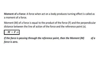
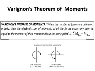
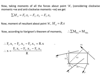
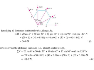
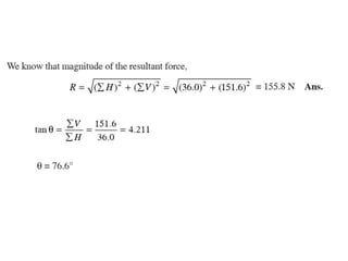
Download to read offline
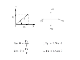
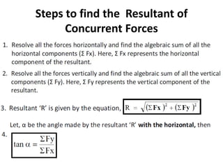
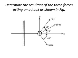
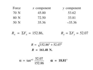
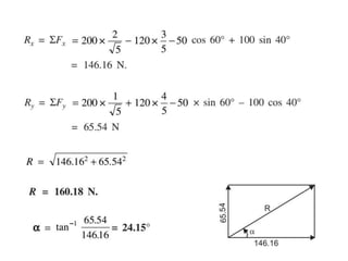


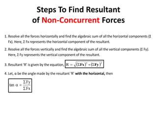
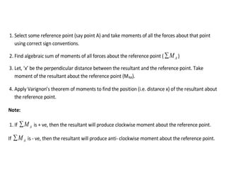
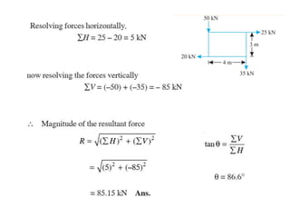
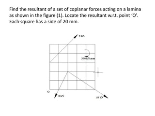
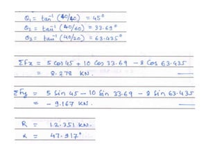
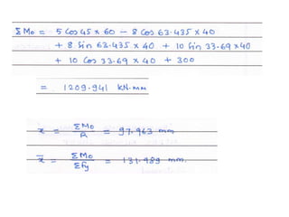
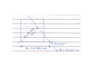

Here are the key steps to solve this problem: 1. Resolve each force into horizontal and vertical components. 2. Take the algebraic sum of the horizontal components to get the horizontal component (Fx) of the resultant. 3. Take the algebraic sum of the vertical components to get the vertical component (Fy) of the resultant. 4. Use the equations: Resultant (R) = √(Fx)2 + (Fy)2 tan(θ) = Fy/Fx to find the magnitude and direction of the resultant. 5. Use Varignon's theorem to locate the position of the resultant from point O. By going through these steps, we find


![Ctm 154[1]](https://cdn.slidesharecdn.com/ss_thumbnails/ctm1541-190506153756-thumbnail.jpg?width=640&height=640&fit=bounds)


