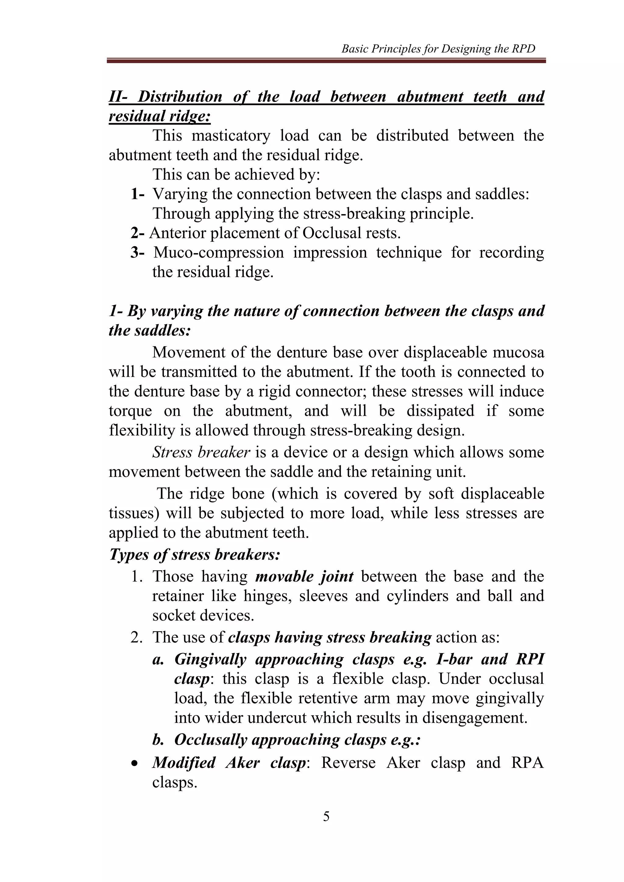
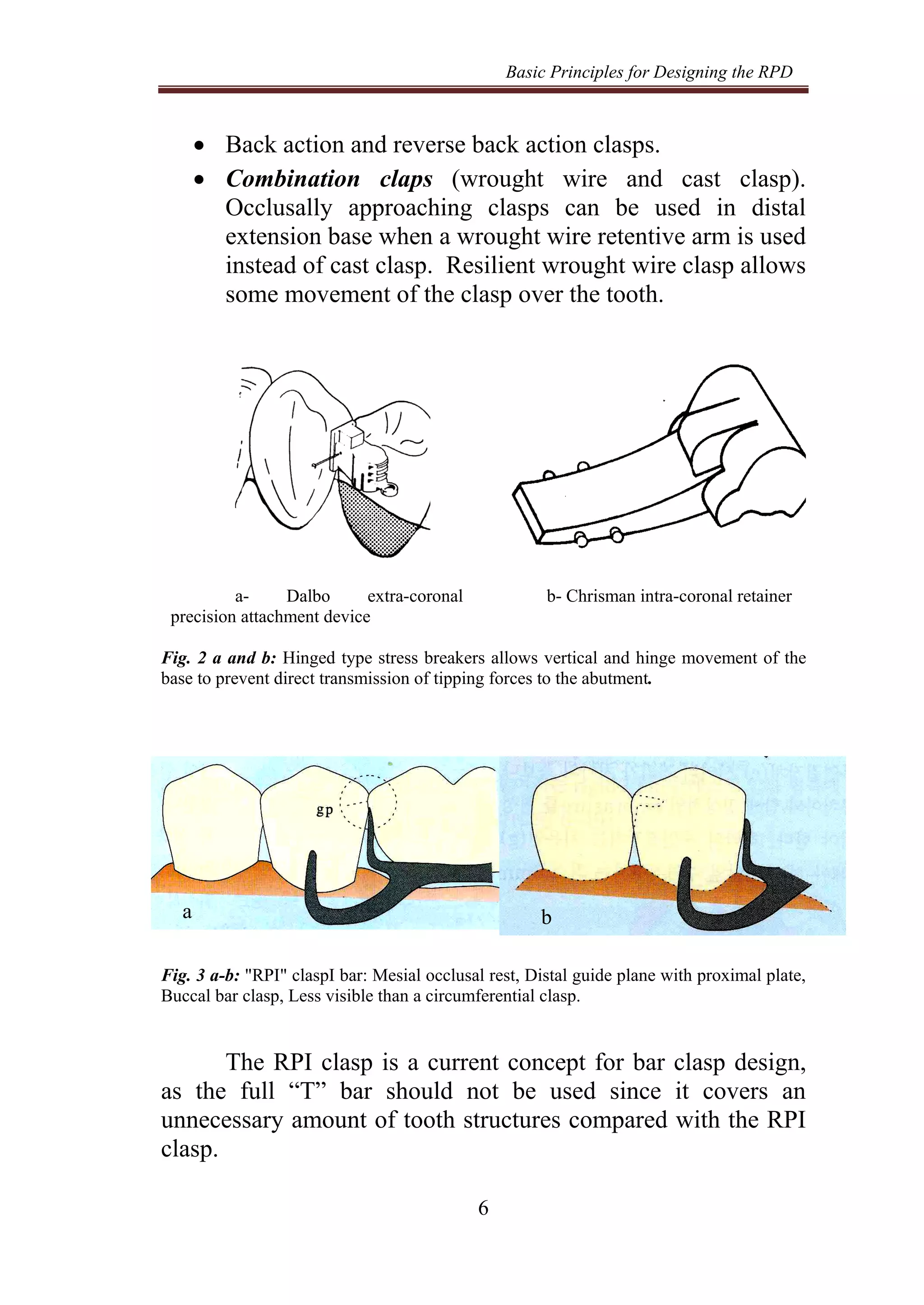
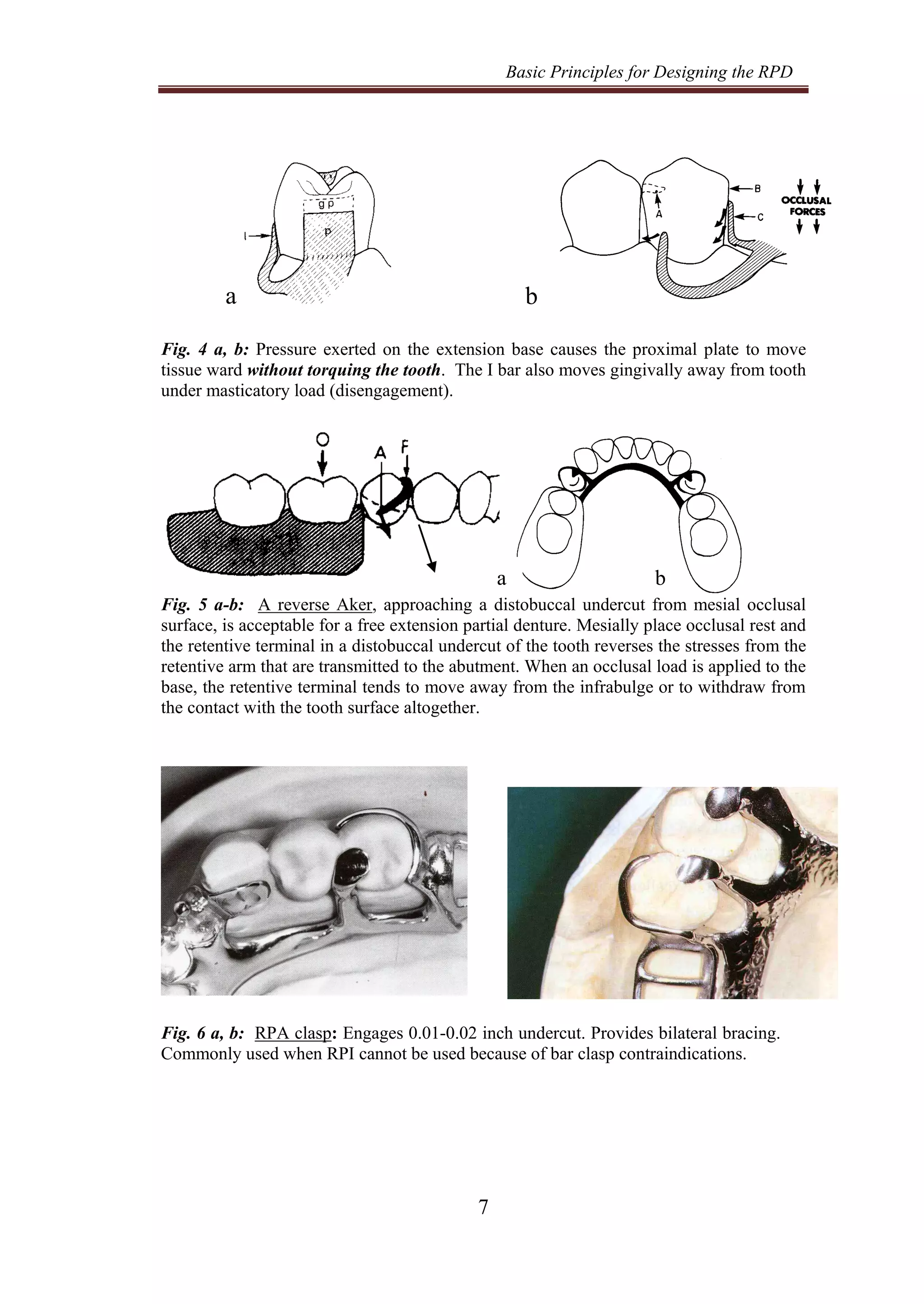
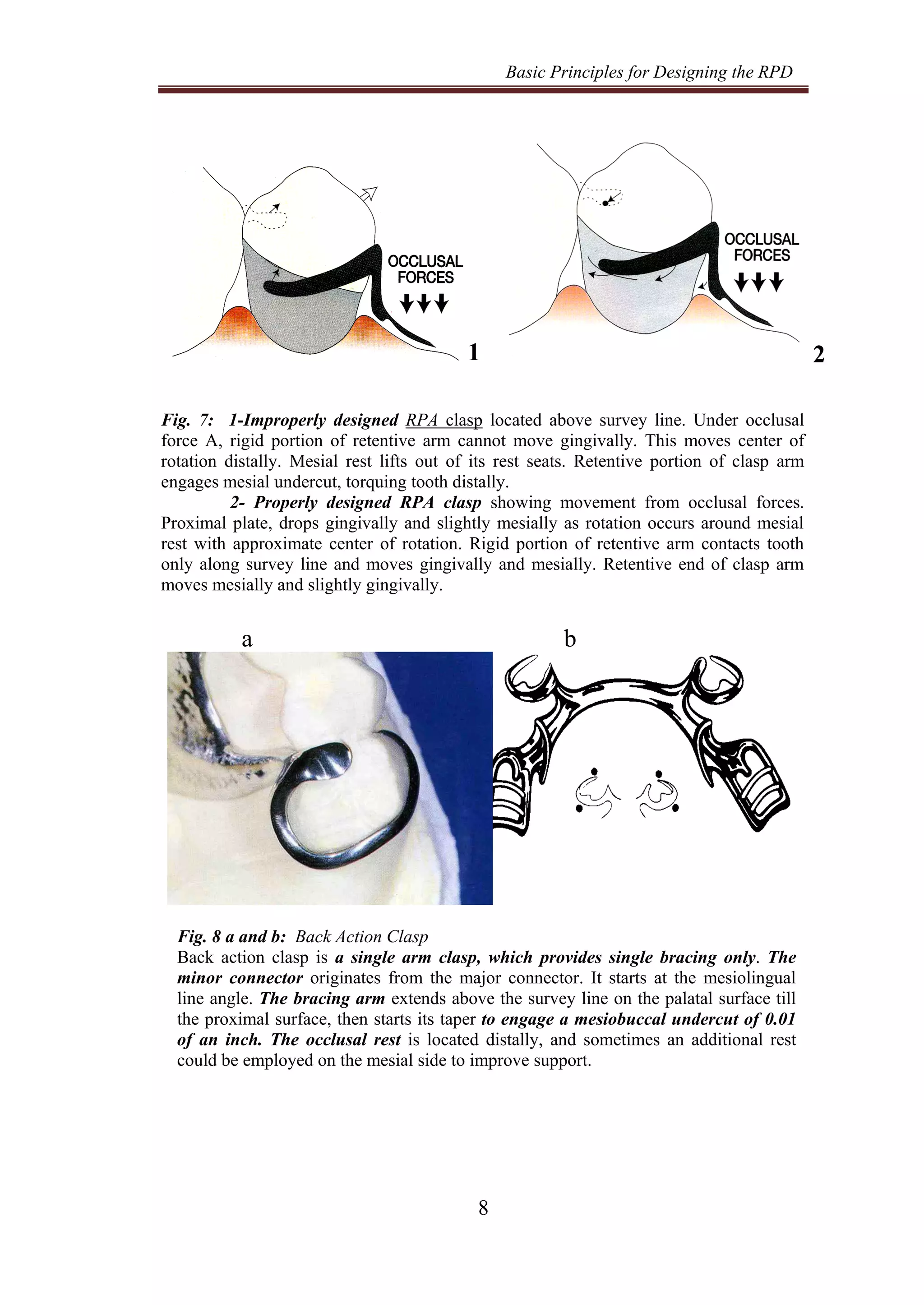
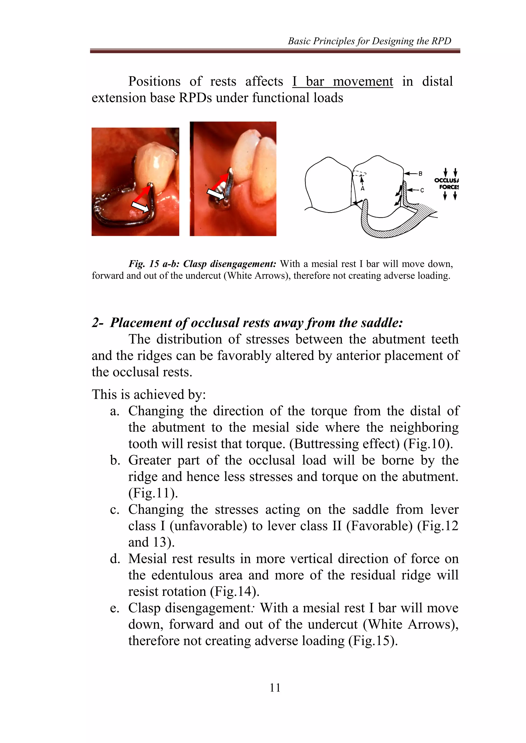
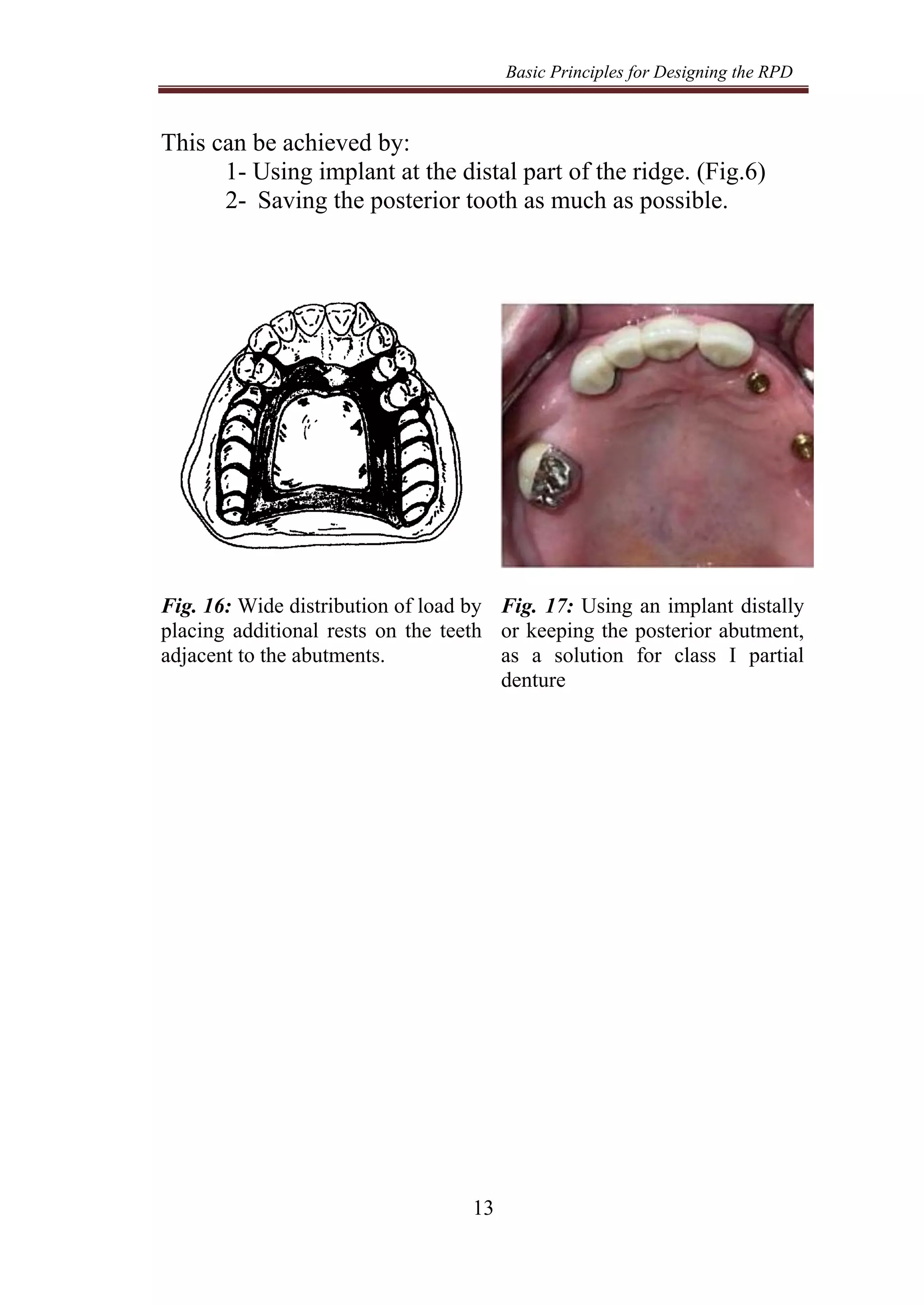
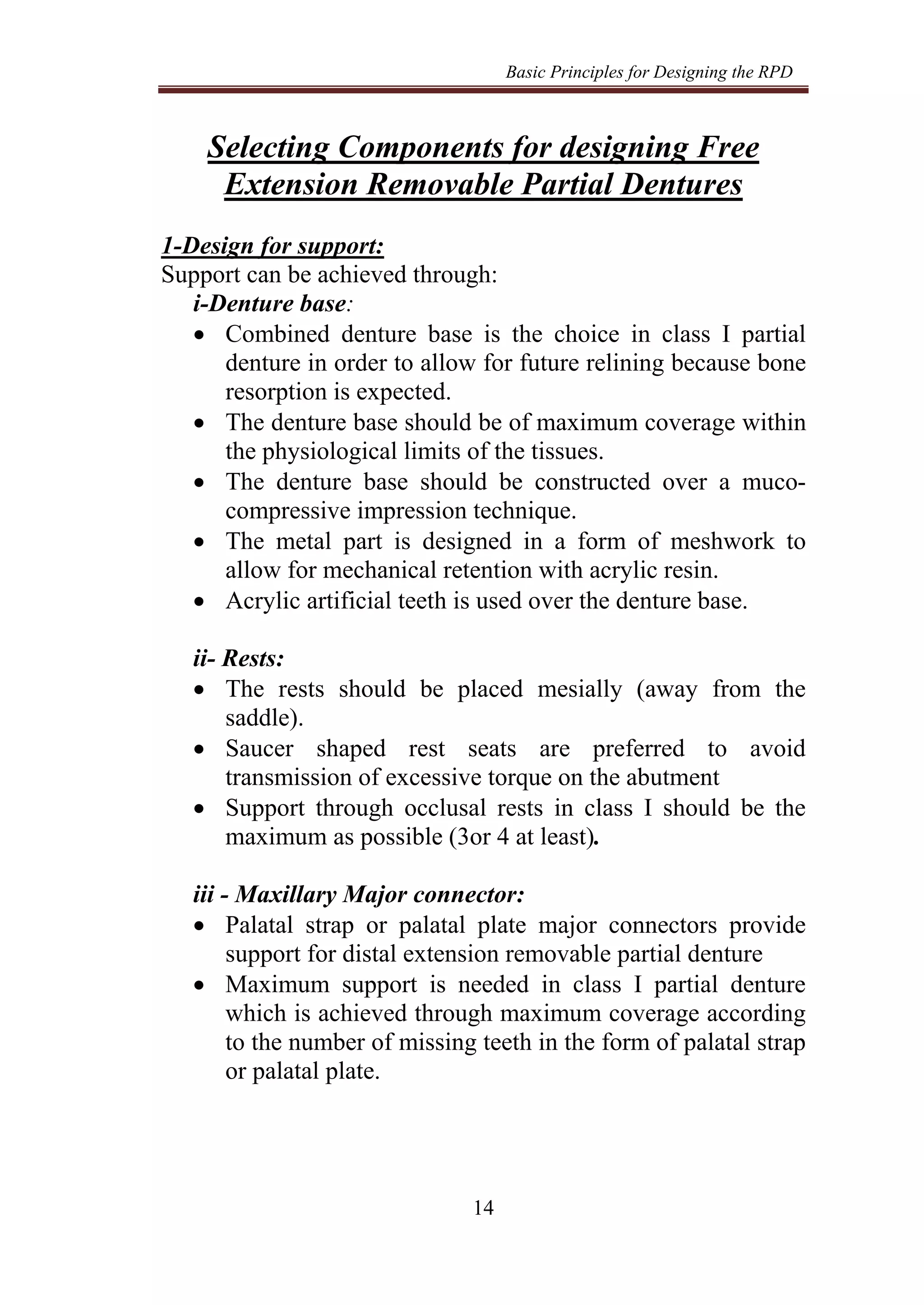
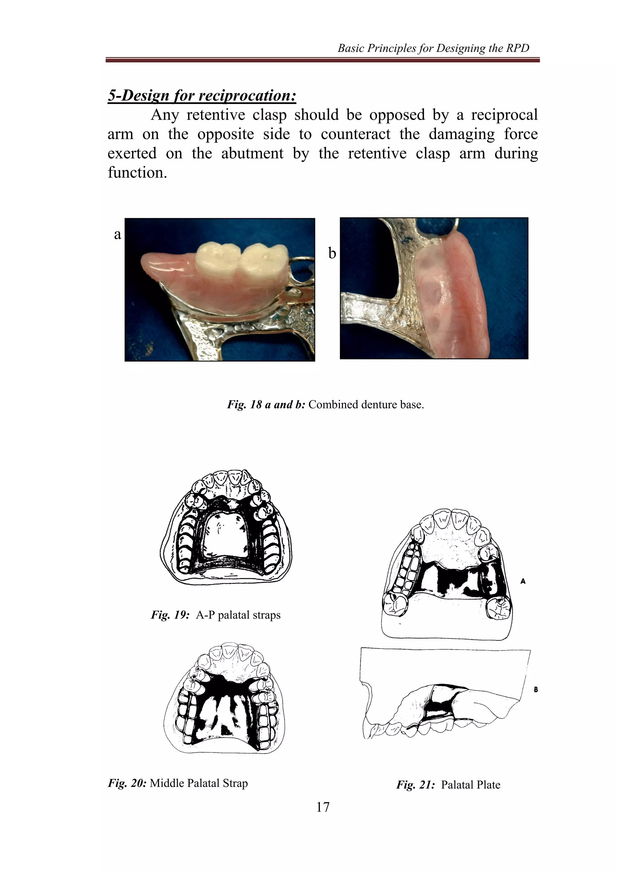
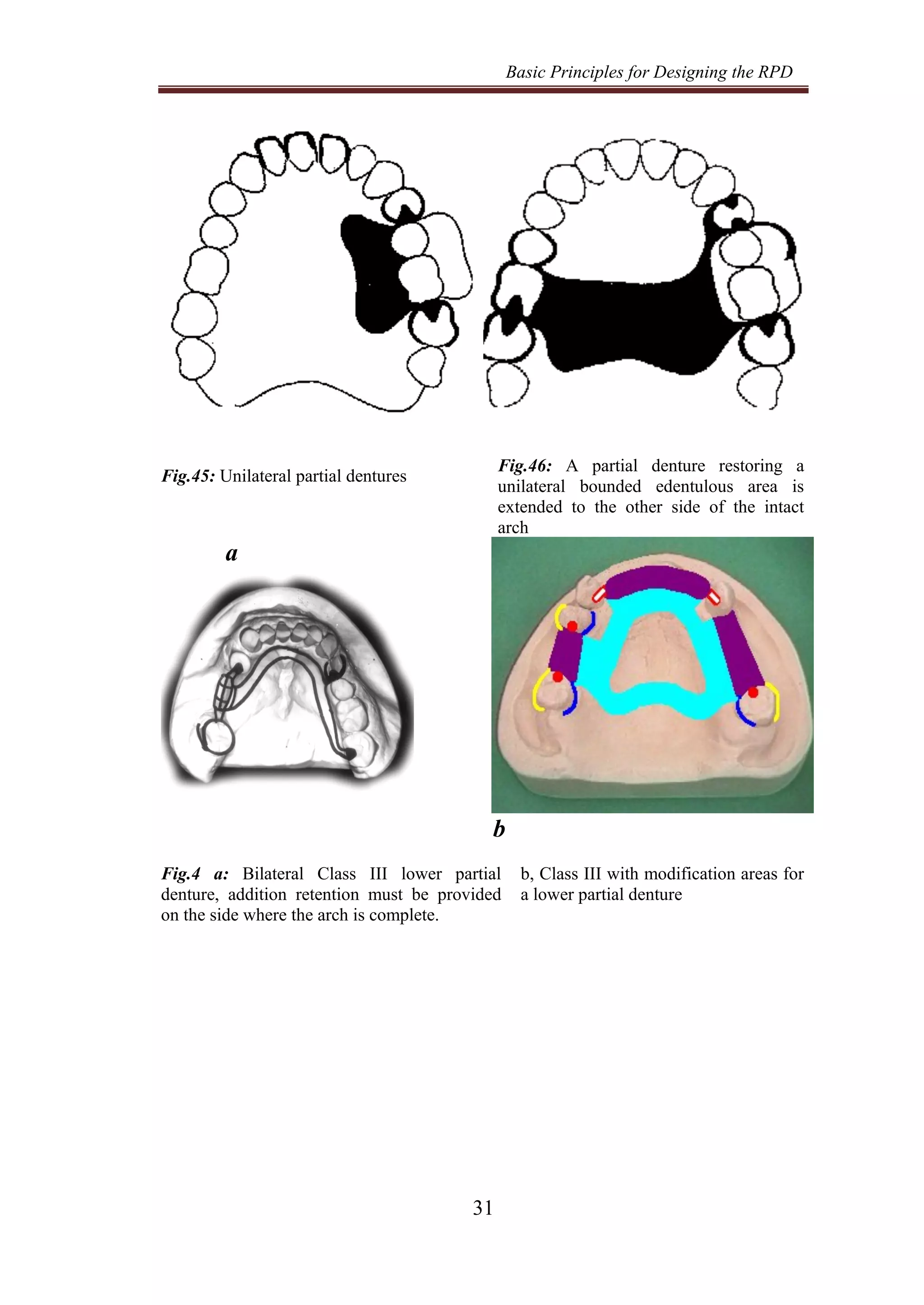
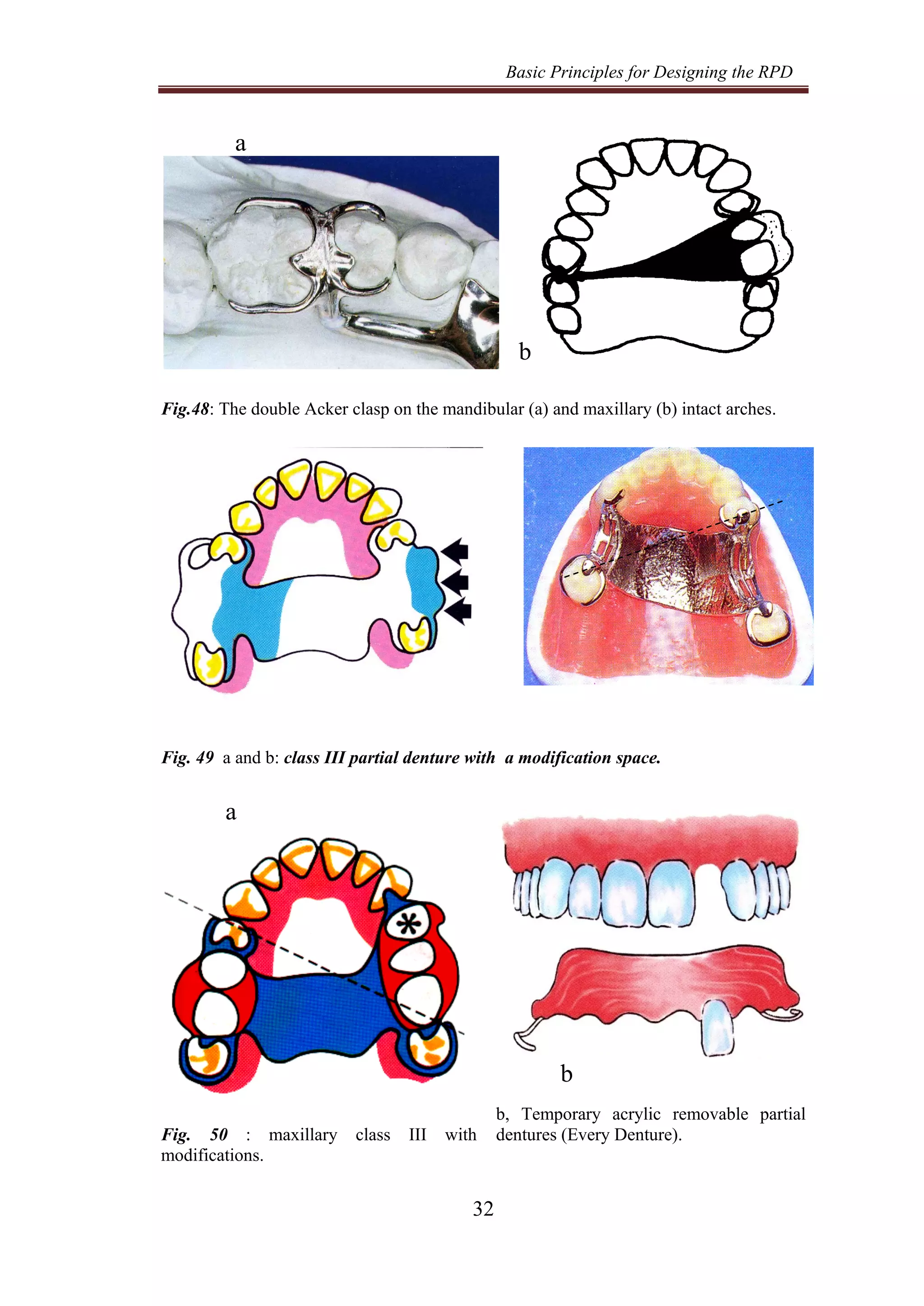
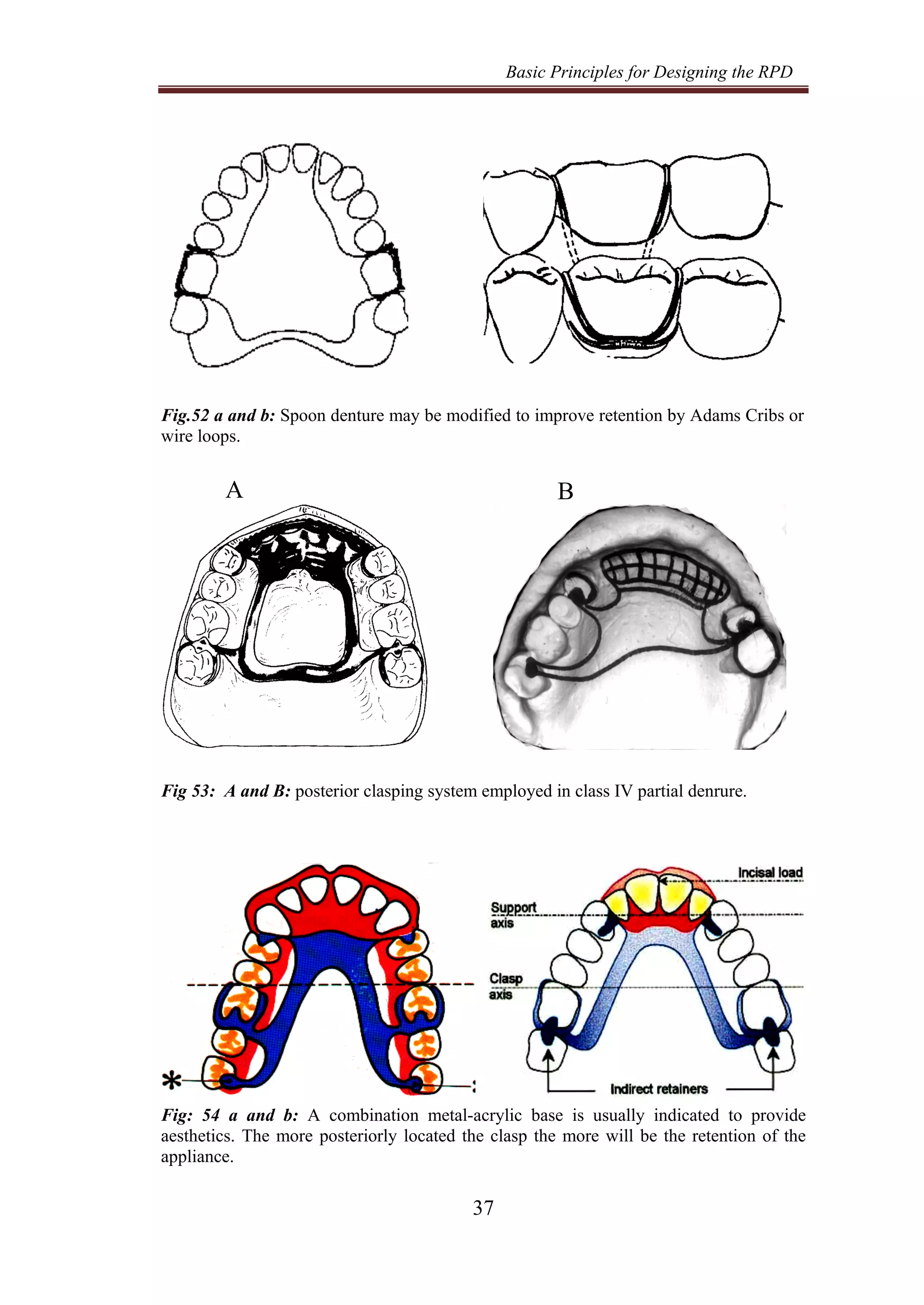
CALL ON ➥9907093804 🔝 Call Girls Hadapsar ( Pune) Girls Service
3-principles of design.pdf
1. Basic Principles for Designing the RPD
1
Basic Principles for Designing the
Removable Partial Denture
• A removable partial denture should restore form and
function and produce adequate aesthetics without
compromising the health of the soft tissues.
• Simple and proper design helps in reducing the harmful
effects on the supporting structures.
• The ability of the supporting structures to tolerate forces is
largely dependent upon the magnitude, the duration and the
direction of these forces in addition to the frequency of
force application.
• The forces acting on partial dentures depends on:
• Age and sex of the patient,
• The power of the muscles of mastication and
• The type of the opposing occlusion.
• Natural teeth are better able to tolerate vertical forces acting
on them. This is because more periodontal fibers are
activated to resist the application of vertical forces.
• On the other hand, lateral forces are potentially destructive
to both the teeth and the bone. Lateral forces should be
minimized in order to be within the physiologic tolerance of
the supporting structures.
Therefore, forces falling on RPD should be properly:
• Directed vertically on both the ridge and the abutment.
• Decreased, within the physiological tolerance of the
tissues.
• Distributed widely to reduce the force /unit area.
A Properly constructed partial denture must achieve:
a-Support: Adequate distribution of the load to the teeth
and mucosa.
b-Retention: Sufficient resistance to vertical displacing
forces.
c- Bracing: Anchorage sufficient to resist horizontal
2. Basic Principles for Designing the RPD
2
forces.
d-Stabilization: Sufficient resistance to resist tipping
forces (Creation of firmness)
e- Reciprocation: Nullifying the effect of pressure on one
side of a tooth by the application of pressure, equal in
amount but in an opposing direction, on the opposite
side of the tooth.
Types of Removable Partial Dentures:
Two distinctly different types of removable partial
denture exist ,either:
1-Bounded partial dentures are that derive their support
from the abutment teeth at each end of the edentulous space.
Functional forces are transmitted through the abutment
teeth to the bone.
2 -Distal extension partial dentures are that derive their
support from the tissues underlying the base and limited support
from the abutment teeth.
The tooth represents a relatively immobile support, but
the mucosa is displaceable to varying degree.
Proper design controls the functional movements of
extension base R.P.D. and achieves favorable biomechanical
outcome.
Possible movements of the partial denture:
At least four possible movements of the partial dentures
exist. They do not occur singularly or independently, but tend to
be dynamic and all occur at the same time.
I- Tissue-ward movements
II- Tissue-away movements
III- Horizontal movements:
a. Lateral movements.
b. Antero-posterior movements.
IV- Rotational movements:
Rotational movements are due to the variation in
compressibility of supporting structures, absence of distal
3. Basic Principles for Designing the RPD
3
abutment at one end or more ends of denture bases, and /or
absence of occlusal rests or clasps at any end of the bases.
1-Rotation of the anterior and posterior extension
denture base around coronal (transverse) fulcrum axis:
a. Rotation of the denture base towards the ridge around
the fulcrum axis joining the two main occlusal rests:
b. Rotation of the denture base away from the ridge
around the fulcrum axis joining the retentive tips of the clasps.
2- Rotation of all bases around a longitudinal axis
parallel to the crest of the residual ridge (Buccolingual or
labiolingual).
3- Rotation about an imaginary perpendicular axis, this
axis either near the center of the dental arch in class I, or is the
long axis of abutment tooth in class II partial denture.
Problems and General Principles Applied For
Kennedy Class I
Problems associated with bilateral free end saddles:
To achieve this goal some difficulties may be
encountered in free-end saddle cases more than in bounded
cases.
1- Exhibits Lack of posterior support and retention due to
lack of posterior abutment.
2- Exhibits combined tooth-support anteriorly and tissue-
support posteriorly. Differences in displaceability
between abutment and mucosa causes rotation of the
denture around a fulcrum axis which Major support is
obtained from the residual ridge which causes residual
ridge resorption.
3- Induces torque on the abutment, results is break down of
their periodontal support.
4- If resorption occurs and relining of the denture is
neglected, further bone resorption occurs.
These difficulties will lead to:
• Ridge resorption is likely to happen.
4. Basic Principles for Designing the RPD
4
• The abutment teeth are subjected to torque in both
antero-posterior and buccolingual directions.
a b
Fig. 1 a and b: Displacement of tissues over edentulous ridge is higher than that of
the abutment teeth. Ridge resorption and torque of the abutment are likely to happen.
Problems of class I Kennedy can be maneged by:
1. Reduction of the load.
2. Distribution of the load between abutment teeth and
residual ridges.
3. Wide distribution of the load.
4. Providing posterior abutment.
I) Reduction of the load:
Reduction of the masticatory load reduces the lateral
component of force that acts on the saddle during mastication,
which can be achieved by:
1. Maximum extension of the denture base with the
functional limits of muscular movement.
2. Decreasing the size of the occlusal table width, by:
a- using canines and premolars instead of premolars and
molars
b- using narrow teeth
c- Leaving a tooth off the saddle.
3. Developing harmonious occlusion and reduce the cusp
angle.
Periodontal ligament
(0.25mm)
Mucosa
(2.0mm)
5. Basic Principles for Designing the RPD
5
II- Distribution of the load between abutment teeth and
residual ridge:
This masticatory load can be distributed between the
abutment teeth and the residual ridge.
This can be achieved by:
1- Varying the connection between the clasps and saddles:
Through applying the stress-breaking principle.
2- Anterior placement of Occlusal rests.
3- Muco-compression impression technique for recording
the residual ridge.
1- By varying the nature of connection between the clasps and
the saddles:
Movement of the denture base over displaceable mucosa
will be transmitted to the abutment. If the tooth is connected to
the denture base by a rigid connector; these stresses will induce
torque on the abutment, and will be dissipated if some
flexibility is allowed through stress-breaking design.
Stress breaker is a device or a design which allows some
movement between the saddle and the retaining unit.
The ridge bone (which is covered by soft displaceable
tissues) will be subjected to more load, while less stresses are
applied to the abutment teeth.
Types of stress breakers:
1. Those having movable joint between the base and the
retainer like hinges, sleeves and cylinders and ball and
socket devices.
2. The use of clasps having stress breaking action as:
a. Gingivally approaching clasps e.g. I-bar and RPI
clasp: this clasp is a flexible clasp. Under occlusal
load, the flexible retentive arm may move gingivally
into wider undercut which results in disengagement.
b. Occlusally approaching clasps e.g.:
• Modified Aker clasp: Reverse Aker clasp and RPA
clasps.
6. Basic Principles for Designing the RPD
6
• Back action and reverse back action clasps.
• Combination claps (wrought wire and cast clasp).
Occlusally approaching clasps can be used in distal
extension base when a wrought wire retentive arm is used
instead of cast clasp. Resilient wrought wire clasp allows
some movement of the clasp over the tooth.
a- Dalbo extra-coronal
precision attachment device
b- Chrisman intra-coronal retainer
Fig. 2 a and b: Hinged type stress breakers allows vertical and hinge movement of the
base to prevent direct transmission of tipping forces to the abutment.
Fig. 3 a-b: "RPI" claspI bar: Mesial occlusal rest, Distal guide plane with proximal plate,
Buccal bar clasp, Less visible than a circumferential clasp.
The RPI clasp is a current concept for bar clasp design,
as the full “T” bar should not be used since it covers an
unnecessary amount of tooth structures compared with the RPI
clasp.
b
a
7. Basic Principles for Designing the RPD
7
a b
Fig. 4 a, b: Pressure exerted on the extension base causes the proximal plate to move
tissue ward without torquing the tooth. The I bar also moves gingivally away from tooth
under masticatory load (disengagement).
Fig. 5 a-b: A reverse Aker, approaching a distobuccal undercut from mesial occlusal
surface, is acceptable for a free extension partial denture. Mesially place occlusal rest and
the retentive terminal in a distobuccal undercut of the tooth reverses the stresses from the
retentive arm that are transmitted to the abutment. When an occlusal load is applied to the
base, the retentive terminal tends to move away from the infrabulge or to withdraw from
the contact with the tooth surface altogether.
Fig. 6 a, b: RPA clasp: Engages 0.01-0.02 inch undercut. Provides bilateral bracing.
Commonly used when RPI cannot be used because of bar clasp contraindications.
a b
8. Basic Principles for Designing the RPD
8
1 2
Fig. 7: 1-Improperly designed RPA clasp located above survey line. Under occlusal
force A, rigid portion of retentive arm cannot move gingivally. This moves center of
rotation distally. Mesial rest lifts out of its rest seats. Retentive portion of clasp arm
engages mesial undercut, torquing tooth distally.
2- Properly designed RPA clasp showing movement from occlusal forces.
Proximal plate, drops gingivally and slightly mesially as rotation occurs around mesial
rest with approximate center of rotation. Rigid portion of retentive arm contacts tooth
only along survey line and moves gingivally and mesially. Retentive end of clasp arm
moves mesially and slightly gingivally.
a b
Fig. 8 a and b: Back Action Clasp
Back action clasp is a single arm clasp, which provides single bracing only. The
minor connector originates from the major connector. It starts at the mesiolingual
line angle. The bracing arm extends above the survey line on the palatal surface till
the proximal surface, then starts its taper to engage a mesiobuccal undercut of 0.01
of an inch. The occlusal rest is located distally, and sometimes an additional rest
could be employed on the mesial side to improve support.
9. Basic Principles for Designing the RPD
9
a
b
Fig. 9 a-b: Combination clasp. consists of cast reciprocal arm and tapered, round
wrought-wire retentive clasp arm .Applicable when disto-buccal undercut cannot be
found or created,
b
Fig. 10 a-b: By changing the direction of torque on the abutment from the distal to the
mesial side of the tooth, the resistance to torque action will be applied from the
neighboring teeth (Buttressing effect ), i.e. Depression of the base does not exert a distal
stress (the pump handle effect) on the abutment but rather a mesial one. Transfer the
design from first class lever force to second Class Lever.
Fig. 11: As rest is moved anteriorly this will
increase the area of support (decrease the force
/unit area). Wide distribution of the load in an
antero-posterior direction. The bone near the
abutment will thus share the distal part of the
ridge in bearing the occlusal load.
Fig. 12: Mesio-occlusal Rest used
to reduced cantilever or class I
lever force when denture rotates
toward residual ridge. Depression
of the base disallowing harmful
engagement of the retentive clasp
arm (clasp disengagement).
10. Basic Principles for Designing the RPD
10
Distal rest Mesial rest
Fig. 13: Placement of the rest adjacent to the extension edentulous area may produce a
tipping force during function, which opens the proximal contacts between teeth and
moves the tooth. Causing mobility and bone loss. Moving the rest mesially also results
in forward and downward movement of the retainers during function, preventing torque
on the teeth.
a b
Fig. 14 a: Mesial rest results in more vertical direction of force on the edentulous area.
b: With a distal rest I bar anterior to the axis of rotation will move up and into
the undercut… therefore creating adverse loading. Red Arrows
Lever arm, represented by distance from rest to denture
base, is increased. This increase in length makes rotational
action caused by up-and down movement of denture base in
function more vertical. A vertical force in better tolerated by
ridge than is a horizontal oblique force.
11. Basic Principles for Designing the RPD
11
Positions of rests affects I bar movement in distal
extension base RPDs under functional loads
Fig. 15 a-b: Clasp disengagement: With a mesial rest I bar will move down,
forward and out of the undercut (White Arrows), therefore not creating adverse loading.
2- Placement of occlusal rests away from the saddle:
The distribution of stresses between the abutment teeth
and the ridges can be favorably altered by anterior placement of
the occlusal rests.
This is achieved by:
a. Changing the direction of the torque from the distal of
the abutment to the mesial side where the neighboring
tooth will resist that torque. (Buttressing effect) (Fig.10).
b. Greater part of the occlusal load will be borne by the
ridge and hence less stresses and torque on the abutment.
(Fig.11).
c. Changing the stresses acting on the saddle from lever
class I (unfavorable) to lever class II (Favorable) (Fig.12
and 13).
d. Mesial rest results in more vertical direction of force on
the edentulous area and more of the residual ridge will
resist rotation (Fig.14).
e. Clasp disengagement: With a mesial rest I bar will move
down, forward and out of the undercut (White Arrows),
therefore not creating adverse loading (Fig.15).
12. Basic Principles for Designing the RPD
12
3- By muco-compression (functional impression techniques):
This impression technique records the mucosa covering
the ridge in its displaced, functional form (not in its anatomic
form).
This impression technique reduces the movement of the
denture base towards the tissues during function therefore
reducing the torque on the abutment.
N.B. Maximum displacement of the tissues should be
avoided to avoid continuous pressure over the mucosa, which
results in pain under the denture.
This can be achieved by:
• Functional impression techniques
• Functional relining after denture construction.
III- Wide distribution of the load:
This can be achieved by:
a. Wide distribution of the load over the ridge by maximum
coverage of the denture base. The broader the coverage,
the greater the distribution of the load.
b. Wide distribution of load over the teeth by placing
additional rest on the tooth adjacent to the abutment or by
embrasure hooks or by splinting.
c. Using Kennedy bar to distribute the load on multiple
teeth.
Lack of posterior retention:
This problem can be overcome by Indirect Retention.
Indirect Retainers are supportive elements, designed to
counteract displacing rotational forces of distal-extension bases.
They may be in the form of rests or palatal connectors.
IV- Providing posterior abutment
The problem of distally extended bases can be solved by
changing the saddle into a bounded saddle and construction of
over denture.
13. Basic Principles for Designing the RPD
13
This can be achieved by:
1- Using implant at the distal part of the ridge. (Fig.6)
2- Saving the posterior tooth as much as possible.
Fig. 16: Wide distribution of load by
placing additional rests on the teeth
adjacent to the abutments.
Fig. 17: Using an implant distally
or keeping the posterior abutment,
as a solution for class I partial
denture
14. Basic Principles for Designing the RPD
14
Selecting Components for designing Free
Extension Removable Partial Dentures
1-Design for support:
Support can be achieved through:
i-Denture base:
• Combined denture base is the choice in class I partial
denture in order to allow for future relining because bone
resorption is expected.
• The denture base should be of maximum coverage within
the physiological limits of the tissues.
• The denture base should be constructed over a muco-
compressive impression technique.
• The metal part is designed in a form of meshwork to
allow for mechanical retention with acrylic resin.
• Acrylic artificial teeth is used over the denture base.
ii- Rests:
• The rests should be placed mesially (away from the
saddle).
• Saucer shaped rest seats are preferred to avoid
transmission of excessive torque on the abutment
• Support through occlusal rests in class I should be the
maximum as possible (3or 4 at least).
iii - Maxillary Major connector:
• Palatal strap or palatal plate major connectors provide
support for distal extension removable partial denture
• Maximum support is needed in class I partial denture
which is achieved through maximum coverage according
to the number of missing teeth in the form of palatal strap
or palatal plate.
15. Basic Principles for Designing the RPD
15
iv- Artificial teeth and Occlusion for class I RPD:
• Smaller acrylic teeth and narrow bucco-lingually are
usually preferred to reduce the occlusal load.
• Teeth should exhibit sharp cutting edges.
• Lower teeth should be placed over the crest of the ridge
to enhance denture stability.
• Positioning of the buccal cusp favorably over the buccal
turning point of the ridge crest.
• Centric occlusion of teeth should coincide with centric
relation
• Simultaneous bilateral contacts of opposing posterior
teeth must occur in centric and eccentric occlusion and in
harmony with the remaining natural teeth.
• Contact of the anterior teeth in eccentric protrusion is
avoided because such contact will lead to unfavorable
forces to maxillary anterior residual ridge and would be
detrimental to the supporting tissues in this area as well
as enhances the instability of the denture.
• Artificial posterior teeth should not be arranged farther
distally than the beginning of sharp upward incline of
residual mandibular ridge or over the retromolar pad, to
avoid shunting the denture stability.
2-Design for connection:
A-Major connector:
• Palatal strap or palatal plate are preferred than
antroposterior palatal bar in the upper denture.
• For the mandibular class I partial denture lingual bars are
preferred due to its simplicity, limited coverage and
patient's tolerance.
• Lingual plate may be the choice when rigidity and
indirect retention is needed.
B-Minor connector:
• It must be rigid.
16. Basic Principles for Designing the RPD
16
• It connects the components of the framework either to the
major connector or to the denture base.
• It touches the tooth in a prepared surface.
• It must cross the gingiva in a perpendicular direction.
3-Design for retention:
A-Direct retention
• Flexible clasp is preferred than rigid clasp to avoid torque
on the abutment.
• RPI or RPA system fulfills the needed requirements.
• If the abutment tooth exhibits an undercut on the disto-
buccal side, a bar clasp can be used.
• If the abutment exhibits an undercut on the mesiobuccal
side, a combination wrought wire clasp is preferred.
B-Indirect retention
• It may be through rests or any rigid components which
extends on the other side of the fulcrum line.
• It should be positioned as far anterior to the fulcrum line
as possible, and perpendicular to it.
• Canine extension provides indirect retention.
• To design the indirect retention, the fulcrum line must be
determined first.
4-Design for bracing and Stability:
Horizontal and rotational forces in class I partial
denture can be resisted through:
• Maximum tissue coverage of the denture base.
• Achievement of balanced occlusion.
• Reducing the occlusal table width.
• Using of cuspless teeth.
• Any rigid components against the vertical walls (e.g.
proximal plates, denture flange).
17. Basic Principles for Designing the RPD
17
5-Design for reciprocation:
Any retentive clasp should be opposed by a reciprocal
arm on the opposite side to counteract the damaging force
exerted on the abutment by the retentive clasp arm during
function.
a
b
Fig. 18 a and b: Combined denture base.
Fig. 19: A-P palatal straps
Fig. 21: Palatal Plate
Fig. 20: Middle Palatal Strap
18. Basic Principles for Designing the RPD
18
Fig. 22: The minor connector should
be thick toward the lingual surface and
tapered toward the contact area.
Fig. 23: A minimum of 5-mm space
between any two neighboring minor
connectors.
Fig. 24: Design for retention through clasps
(flexible clasp is used)
Fig. 25: The rest on an anterior tooth,
(indirect retainer) resists the tendency for
the denture to pivot.
a b
Fig. 26 a and b: Lateral borders of the ridge must be covered to provide bracing and
stability for distal-extension dentures.
19. Basic Principles for Designing the RPD
19
Fig. 27, 1-3: horizontal forces are generated during function by occlusal contact (1 and 2
) and by the oral musculature surrounding the denture (3). These forces attempt to
displace anteroposterior and lateral directions.
b
Fig.28, a and b: A guide surface* allows a reciprocating component to maintain
continuous contact with a tooth as the denture is displaced occlusally. The retentive
arm of the clasp is thus forced to flex as it moves up the tooth. It is this elastic
deformation of the clasp that creates the retentive force.
a b
Fig. 29 a and b: different designs for mandibular distal-extension bases.
Retentive
distance
a
20. Basic Principles for Designing the RPD
20
a b
c d
Fig. 30 a-d: Possible designs for class I partial dentures with pier abutment
Anterior Modification spaces of class I are preferably
restored separately with fixed bridge. This helps in simplifying the
partial denture design. Saving the anterior ridge from resorption
and the anterior abutments from torque resulting due to
movements of the anterior saddle occurring as a result of rotation
of the posterior free end saddle. Other alternative treatment is to
construct a class I with Modification spaces partial denture but
without placing retentive element on the pier abutment but only
support (why).
Pier
abutment
Fixed
bridge
21. Basic Principles for Designing the RPD
21
Problems and General Principles Applied For
Kennedy Class II
Designing class II partial dentures usually follow the
same basic principles of class I partial dentures as the problems
resulting from absence of posterior abutment, which causes lack
of proper posterior support and retention.
• The difference of displaceability of the supporting tissues
results in tissue-ward and tissue-away movements of the
denture base with subsequent torque on the abutment.
• The absence of a saddle on the other side of a class II
partial denture complicates the problems of retention and
stability of the denture. To enhance the benefit of class II
partial denture, cross arch stabilization and additional
retention must be provided from the opposite side where
the arch is intact. It can be easily secured by clasping
more than one tooth on this side, and/or using more rigid
types of clasps.
As far as the design is concerned, class II dentures divide
into two groups,
I- Designing of class II partial dentures with no
modifications:
1- Direct retention is obtained by:
a- Rigid clasping and rigid connection between the saddle
and the retainer. This design is indicated in case of short
edentulous span bounded by a strong abutment with
healthy periodontium, and well formed edentulous ridge
covered with firm mucosa of normal thickness.
b- Designs applying stress equalizing principles
This design is applied in long class II cases.
- Anterior placement of occlusal rest.
- Using stress equalizing design e,g. flexible
clasps as RPI, RPA, reverse Aker, RLS, back
action, and reverse back action clasps as well
22. Basic Principles for Designing the RPD
22
as combination clasp (wrought wire with
casted clasp)
2- A double Aker clasp is usually used on the dentulous side.
3- An indirect retainer should be provided to counteract
rotation of the denture away from the tissues.
II- Designing of class II partial dentures with modification
spaces:
The presence of modification spaces on the opposite side
of Kennedy class II simplifies the partial denture design. The
problem of retention is solved by the presence of saddles on the
modification area. The clasps on abutments bounding the
modification area provide retention, bracing and reciprocation
together with indirect retention.
a, Rest b, Finishing line
c, d: Minor connectors
e, Major connectors and denture bases f, Completed Drawing of the design on the
master cast
Fig. 31: (a- f): Drawing the design on the master cast
23. Basic Principles for Designing the RPD
23
Tripod configuration:
It is used primarily for class II arches if there is a
modification space on the dentulous site. When the distal
abutment on one side of the arch is missing, the inevitable lever
is created by the distal extension base. In this case, the leverage
may be controlled, to some degree, by creating a triangular
pattern of clasp placement.
a b
Fig. 32 a and b: A-Rigid clasping and rigid connection between the saddle and the
retainer. An indirect retainer should be provided to counteract rotation of the denture
away from the tissues.
Fig. 33: Class II lower partial dentures:
The clasp line should divide the denture
into two equal halves. Addition retention
must provided on the side where the arch
is complete. Designs applying stress
equalizing principles.
Fig. 34: Indirect retention might be used
in case of class II without modification. A
double Aker clasp usually used on the
dentulous side
24. Basic Principles for Designing the RPD
24
Fig. 35 a-b: A and B: Tripoding configuration.Class II lower partial dentures with
modification space. The presence of modification spaces on the opposite side of
Kennedy class II simplifies the partial denture design. b, Class II lower partial dentures
using rigid connection.
Fig. 36 a and d: Different designs for class II with modifications.
a a
b
Fig. 37: RII indicated for posterior teeth
or a single isolated last molar, buccal and
lingual “I” bars.
Fig.38: Ring Clasp The ring clasp is a
single-arm clasp, indicated on tilted,
isolated molars. A reinforcing arm and an
auxiliary distal rest
B
A
25. Basic Principles for Designing the RPD
25
a
b
Fig.39: The ring clasp. It is a single arm clasp,
indicated on tilted, isolated molars.
Fig.40: Minor connectors Join the
major connector at right angle to
cover as little as possible of the
gingiva
Problems and General Principles Applied For
Kennedy Class III
Bounded, unilateral edentulous spaces of varying lengths
represent the class III cases.
Problems associated with unilateral bounded cases
Controversy exists regarding the restoration of short
edentulous gaps by removable partial dentures. Two opinions
exist. These are:
1- Restoration of any missing tooth is necessary in order to
a. Restore the integrity of the dental arch, prevent tilting,
drifting, rotation or over eruption of the remaining
natural teeth.
b. Restore the masticatory mechanism.
c. Restore aesthetics.
2- It is not practical to restore a single tooth or a short span
unilateral area especially in cases having bad oral
hygiene and caries susceptibility. However, frequent
examinations are necessary to detect any changes that
may affect the integrity of the arches or the masticatory
function.
26. Basic Principles for Designing the RPD
26
I- Restoration of the unmodified class III
Three lines of treatment are proposed for the treatment of
unilateral bounded areas. These are:
1- Fixed Bridges are usually the treatment of choice for short
span bounded edentulous areas when abutments are strong
and healthy and minimum bone loss exists.
2- Unilateral Partial Dentures: Unilateral partial dentures are
also called side plates or removable bridges. They are
constructed to restore one side of the arch and are not
extended to the opposite side. Hence, they lack adequate
retention and stability, permit limited load distribution and
are not safe to use due to the probability of being inhaled or
swallowed (Fig. 11-39 a, b and c).
However, this unilateral design provides least amount of
tooth preparation and least amount of tooth and soft tissue
contact.
Unilateral prosthesis
Leverage per se is not a problem with the unilateral type
of edentulous span. However, torsional stresses on the
abutments are generated by the prosthesis because of its
tendency to rotate in a buccolingual plane. The conventional
solution is to cross the arch with a major connector and to clasp
teeth on the contra-lateral side, thus making the prosthesis, in
effect, bilateral in design. Ordinarily this is the preferred
approach to the problem. If the unilateral design must be used,
all four clasp arms should be made retentive in order to
minimize the tendency of the prosthesis to rotate around a line
that extends mesio-distally through the two abutment teeth.
For unilateral removable partial denture to be successful:
A. Clinical crown of the abutment tooth must be long
enough to resist rotational forces.
B. The buccal and lingual surfaces of the abutment tooth
must be parallel to resist tipping forces.
27. Basic Principles for Designing the RPD
27
C. Retentive undercuts should be available on both the
buccal and lingual surfaces of each abutment.
Unilateral removable partial denture should be used with
caution. As the chance of the denture becoming dislodged and
aspirated is too great.
Fig.41: For unilateral removable partial
denture to be successful, clinical crown of
abutment tooth must be long enough to
resist rotational forces.
Fig.42: The buccal and lingual surfaces
of the abutment tooth must be parallel to
resist tipping forces.
Certain measures are undertaken to avoid instability of
unilateral partial dentures, these are
a) Providing working side contact on both buccal and
lingual cusps. This allows transmission of forces on both
buccal and lingual cusps. Thus, the resultant of the two
forces acts within the confines of the occlusal rest
favoring stability of the denture.
b) Maximum extension of the occlusal rest especially to the
bucca1 side. This keeps the axis of rotation as far
buccally as possible and ensures transmission of vertical
component of force lingual to this axis.
c) Providing adequate bracing against lateral movement
especially buccal movement. This can be achieved by:
1. Extending the denture base on the vertical slope of the
hard palate.
2. Bracing arms located on the abutment tooth and the tooth
adjacent to it.
3. Clasping adjacent teeth to allow wider load distribution.
4. Using box-shaped rest seat preparations to supplement
bracing.
28. Basic Principles for Designing the RPD
28
d) Providing adequate retention against both vertical
displacement and buccal displacement. This can be
achieved by using clasps that provide both buccal and
lingual or palatal retention i.e. a clasp with bilateral
bracing and retention.
Contra indications of unilateral partial dentures:
Unilateral partial dentures are contra indicated in the
following cases:
1. Patients employing excessive lateral movement during
mastication.
2. Patients exhibiting bruxism.
3. Conical shaped abutment teeth, weak teeth or teeth
having short crowns that cannot provide adequate
retention and bracing.
4. In old patients.
3-Bilateral Partial Dentures:
A partial denture restoring a unilateral bounded
edentulous area is preferably extended to the other side of the
intact arch rather than using a side plate. Bilateral removable
partial dentures provide better stability and retention together
with wider load distribution.
A-bilateral unmodified class Ill partial denture is
designed as follows:
1- Denture base: Metallic denture base is designed to fit
the static rather than the functional form of the ridge.
2- Rests: rests are usually placed on the near zone of the
abutment teeth to provide adequate support. Rest seats can be
prepared in either a box-shaped or saucer-shaped configuration
depending on the condition of the abutment teeth.
3-Clasps: Rigid clasping is usually required for class III
cases bounded by strong abutments. The clasps are located on
abutments bounding the edentulous span. A third clasp, which
29. Basic Principles for Designing the RPD
29
may either be an embrasure or a multiple clasp is used on the
intact (dentulous) side.
4. Major connectors: A lingual bar for mandibular
dentures. A palatal bar or palatal strap for maxillary major
connector are usually used.
II- Class III having modification areas:
- When a modification space is present on a class III
partial denture the same principles for designing a bilateral
denture are followed, the tripod clasp configuration is usually
efficient. However, four supporting rests should be used one on
each abutment bounding the edentulous areas.
- Class III cases having long edentulous spans bounded by
a periodontally affected abutment tooth and having
modification spaces are usually considered tooth-tissue
supported dentures.
- Maximum coverage of the residual ridge and palatal
tissues is required to provide adequate denture support.
- Retention of the denture results from physical forces as
adhesion together with flexible wrought wire clasps located on
the abutment teeth. These cases could also be restored by an
Every denture which is a totally mucosa-borne denture.
Every’s denture (Acrylic denture base):
It can be used for restoring multiple bounded saddle areas
in the upper jaw; its characteristics are as follows:
1. All borders are at least 3mm from the gingival margins.
The “Open” design of saddle/tooth junction is employed
helps in the prevention of stagnation areas.
2. Broad area coverage is required to resist vertical load.
3. Palatal tissues and the posterior standing teeth resist
lateral load.
4. Posterior wire “stop” is included to prevent distal drift of
the posterior teeth with subsequent loss of contact points.
The palate and the posterior standing teeth resist antero-
posterior load.
30. Basic Principles for Designing the RPD
30
5. Point contact between the artificial teeth and abutment
tooth is established to reduce lateral stresses to a
minimum.
6. Lateral stresses are reduced by achieving as much
balanced occlusion and articulation as possible.
Retention of the denture is achieved by:
- Adhesion resulting from optimum coverage of the
denture foundation tissues and full extension of the flanges into
the functional width and depth of the sulcus.
- Proper post damming.
- Proper shaping of the polished surface to benefit from
muscular control.
- Free sliding occlusion to minimize denture displacement
during lateral movements.
Quadrilateral configuration:
It is indicated most often for class III arches particularly
when there is a modification space on the opposite side of the
arch. When four abutment teeth are available for clasping, and
the partial denture can be confined within these four clasps, all
leverage is neutralized.
Fig.43: When four abutment teeth are
available for clasping the quadrilateral
clasping consists of a retentive clasp at
each end of edentulous space. This
provides maximum retention and stability,
all leverages are neutralized.
Fig.44: Leverage, as such is not a problem
with the unilateral type of RPD, although
torsional stresses on the abutment teeth are
operant because of the tendency of the
prosthesis to rotate around a line that
extends through the occlusal rests of the two
clasps.
31. Basic Principles for Designing the RPD
31
Fig.45: Unilateral partial dentures
Fig.46: A partial denture restoring a
unilateral bounded edentulous area is
extended to the other side of the intact
arch
a
b
Fig.4 a: Bilateral Class III lower partial
denture, addition retention must be provided
on the side where the arch is complete.
b, Class III with modification areas for
a lower partial denture
32. Basic Principles for Designing the RPD
32
a
b
Fig.48: The double Acker clasp on the mandibular (a) and maxillary (b) intact arches.
Fig. 49 a and b: class III partial denture with a modification space.
a
b
Fig. 50 : maxillary class III with
modifications.
b, Temporary acrylic removable partial
dentures (Every Denture).
33. Basic Principles for Designing the RPD
33
a b
Fig.51 a and b : Temporary acrylic removable partial dentures (Every Denture).
Problems and General Principles Applied For
Kennedy Class IV
Kennedy class IV partial dentures replace an anterior
bounded saddle which lies anterior to the abutment teeth.
- Fixed partial denture is the treatment of choice but
removable restoration is preferred in children
- The saddle varies in length and may even extend to
replace posterior teeth on both sides.
Problems associated with class IV partial dentures:
1-Class IV partial dentures usually follow the same basic
principles of class I partial dentures, and are considered as
free-end partial dentures.
The edentulous area is crossing the midline and lies
anterior to the abutments, they are tissue-supported anteriorly
and tooth-supported posteriorly. This leads to rotation of the
denture base around a fulcrum axis formed by the line joining
the supporting rests. This rotation induces torque on the
abutments.
The amount of torque depends on:
34. Basic Principles for Designing the RPD
34
a) Displaceability of the mucosa covering the residual
ridge.
b) Curvature of the arch: The more curved the dental
arch, the more distant will be the location of artificial
anterior teeth, the more will be the magnitude of
displacing forces leading to excessive torque on
abutment teeth.
c) Degree of bone resorption; whereas excessive ridge
resorption induces more torque.
2-Class VI partially edentulous cases may occur at any age
even in children and adolescents. The loss of upper
anterior teeth may be due to damage from trauma
especially in children and are less liable to caries.
3-The line of treatment of anterior edentulous areas differ
depending on the age of the patient. It is either:
• Fixed bridge (preferable)
• Spoon denture
• Acrylic temporary partial denture.
• Metallic frame work partial denture.
Young patients are usually treated with a temporary
appliance until a stable mouth condition is reached,
4-Frequent inspections are necessary to detect the need for
relining or rebasing the dentures.
Restoration of class IV cases
1-Kennedy Class IV Designs for Children:
- The spoon denture is usually used as a temporary
appliance for young adults and children. Thus, it should
be simply designed and safe.
- The spoon denture is a mucosa-borne partial denture,
which is constructed in acrylic resin.
35. Basic Principles for Designing the RPD
35
2-Class IV skeleton design for short spans
Class IV skeleton design is an alternative line of
treatment to fixed bridges. They are indicated in the following
conditions:
- Cases where marked bone resorption necessitates the
addition of an anterior flange to restore esthetics and
provide lip support.
- Patients who refuse extensive preparation required to
prepare the abutments supporting the bridge.
- Cases having markedly curved edentulous span because
this may add excessive stresses on abutments.
3-Class IV design for long edentulous spans
Long anterior edentulous areas, which may extend to
include premolars usually, occur in adults. Hence, a permanent
restoration in the form of metal partial dentures is the treatment
of choice.
Design for Class IV metallic framework partial denture
1- Design for support:
• A combination of metal and acrylic base is indicated
because it is considered tooth-tissue supported partial
denture and future relining is expected.
• Sufficient support should be applied through rests on the
abutments adjacent to the edentulous span.
• The rests on the adjacent abutments act as a fulcrum, so
posterior retention should be sufficient to resist rotational
movements, especially for ovoid or tapered arch.
• Cingulum rests or Occlusal rests are used on both sides
of the edentulous area.
• Incisal rests are avoided as much as possible for esthetic
reasons, and to avoid stresses on weak teeth.
36. Basic Principles for Designing the RPD
36
2-Design for retention:
• Multiple clasps (or embrasure clasp) are used on the last
standing molar teeth.
• The more posteriorly located the clasp the more retention
and the more widely distributed the stresses and torque
action.
• Posterior retention resists rotation around the anterior
fulcrum line.
3-Design for connection:
• In case of class IV for short span major connection is in
the form of two palatal bars arising from the saddles and
extending posteriorly on the lateral walls of the palate,
equidistant between the gingival margin and the midline
of the palate. The distal ends of the two bars are attached
to the posteriorly located clasps.
• Lingual bar connector is used in mandibular dentures.
• A horse-shoe major connector may be used .Its
disadvantage is its lack of rigidity which is avoided by
extending it distally.
• In long span class IV: The two palatal bars give
flexibility to the major connector (not required). So,
Palatal strap or anteroposterior palatal bars are used.
4-Design for Indirect Retention:
• Indirect retention to counteract rotation around the
fulcrum axis is obtained by rests on the posterior teeth
(tooth support) and by extending the palatal strap major
connector posterior to fulcrum axis (mucosal support).
• Mucosal support indirect retainer is limited to the upper
denture.
• Occlusal rests are applied to the most far occlusal surface
as possible and on both sides of the arch.
37. Basic Principles for Designing the RPD
37
Fig.52 a and b: Spoon denture may be modified to improve retention by Adams Cribs or
wire loops.
A B
Fig 53: A and B: posterior clasping system employed in class IV partial denrure.
Fig: 54 a and b: A combination metal-acrylic base is usually indicated to provide
aesthetics. The more posteriorly located the clasp the more will be the retention of the
appliance.