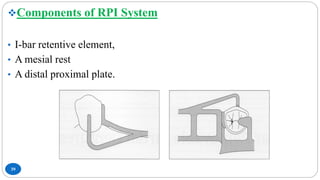
This document provides an overview of removable partial denture (RPD) design, with a focus on the RPI and RPA systems. It discusses the challenges of tooth-tissue supported prostheses and how RPD design can control damaging forces. The RPI system aims to minimize stress using components like I-bar retainers, mesial rests, and proximal plates. Variations like Krol's modification require less tooth alteration. Indirect retention through rests helps redistribute forces. The document reviews factors like clasp design, material, and position that also influence stress control.


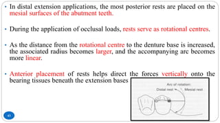
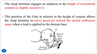


![CTEV [ clubfoot] DR ARUN LAL ,DR MOHAMED ASHRAF travancore medical college k...](https://cdn.slidesharecdn.com/ss_thumbnails/ctevclubfootdrarunlaldrmohamedashraftravancoremedicalcollegekollamkeralaindia-260208063247-18fc466c-thumbnail.jpg?width=640&height=640&fit=bounds)


