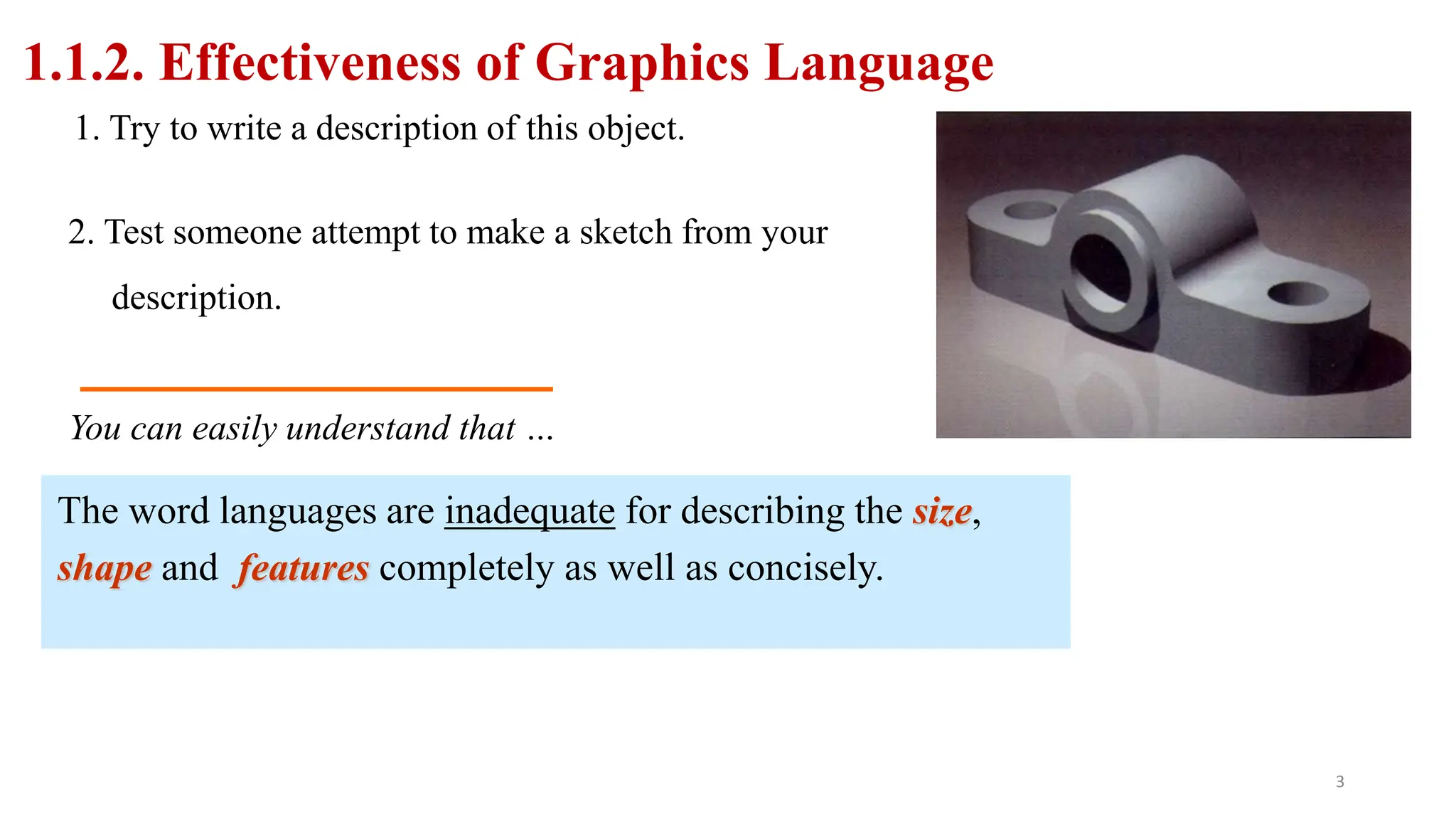
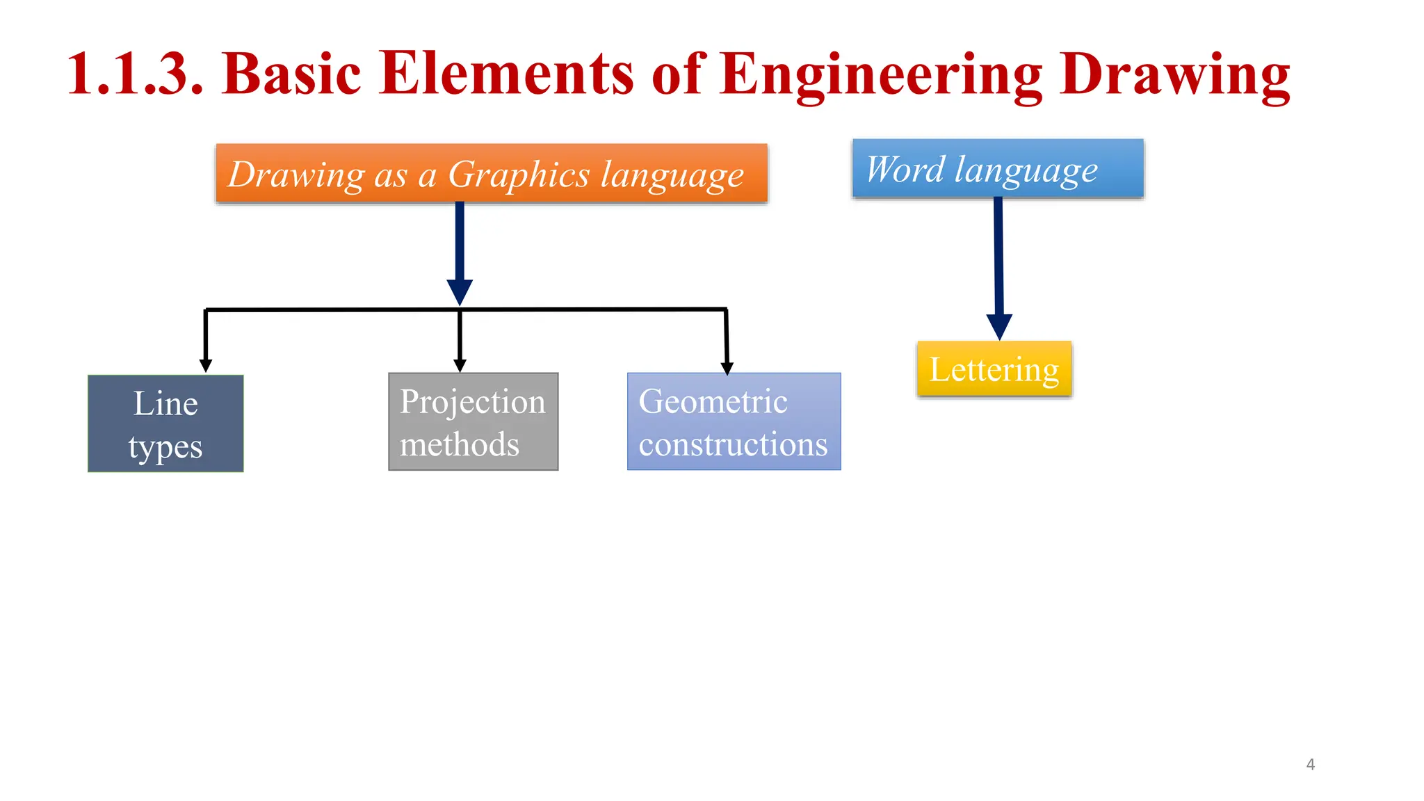
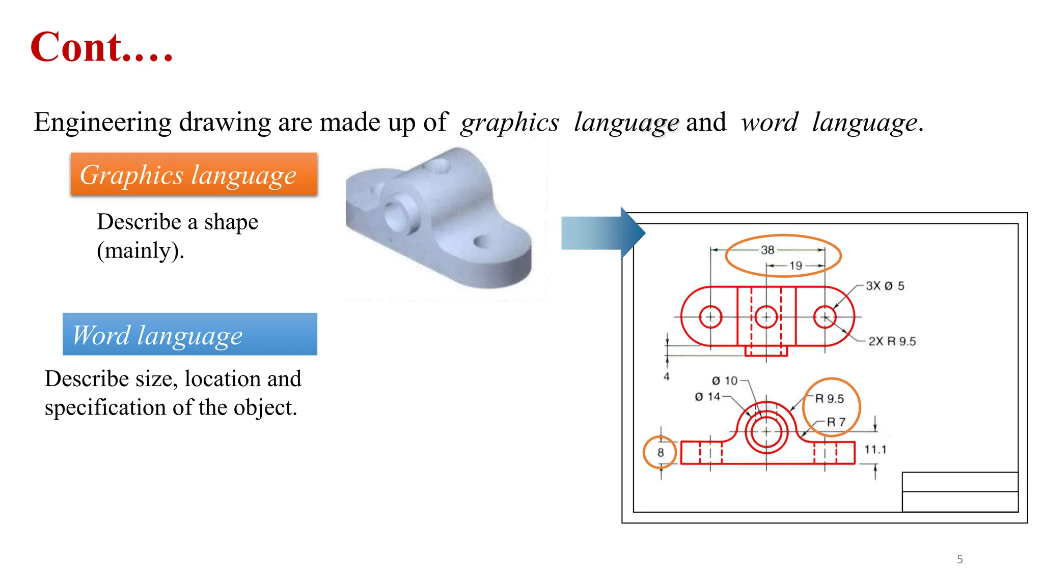
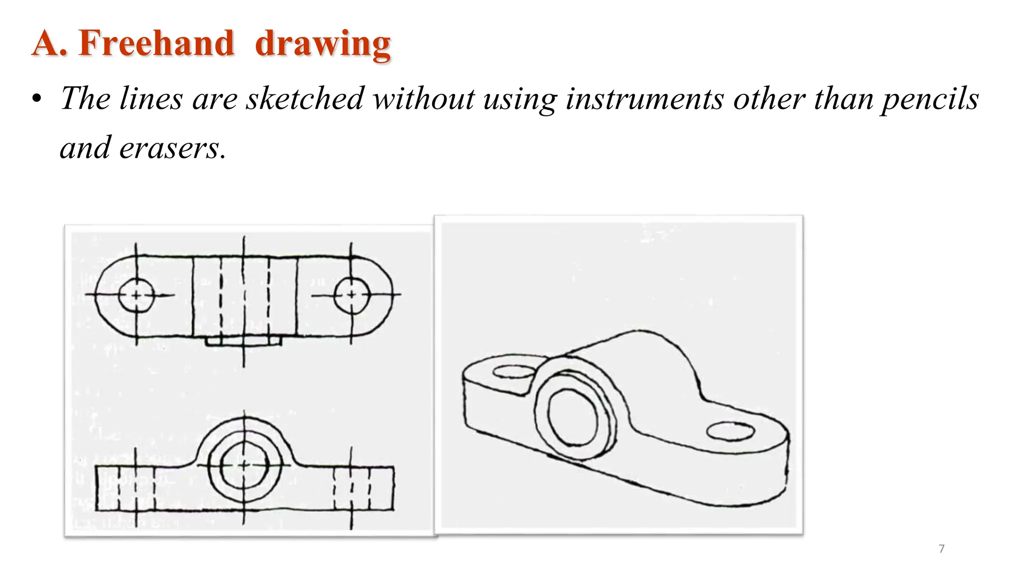
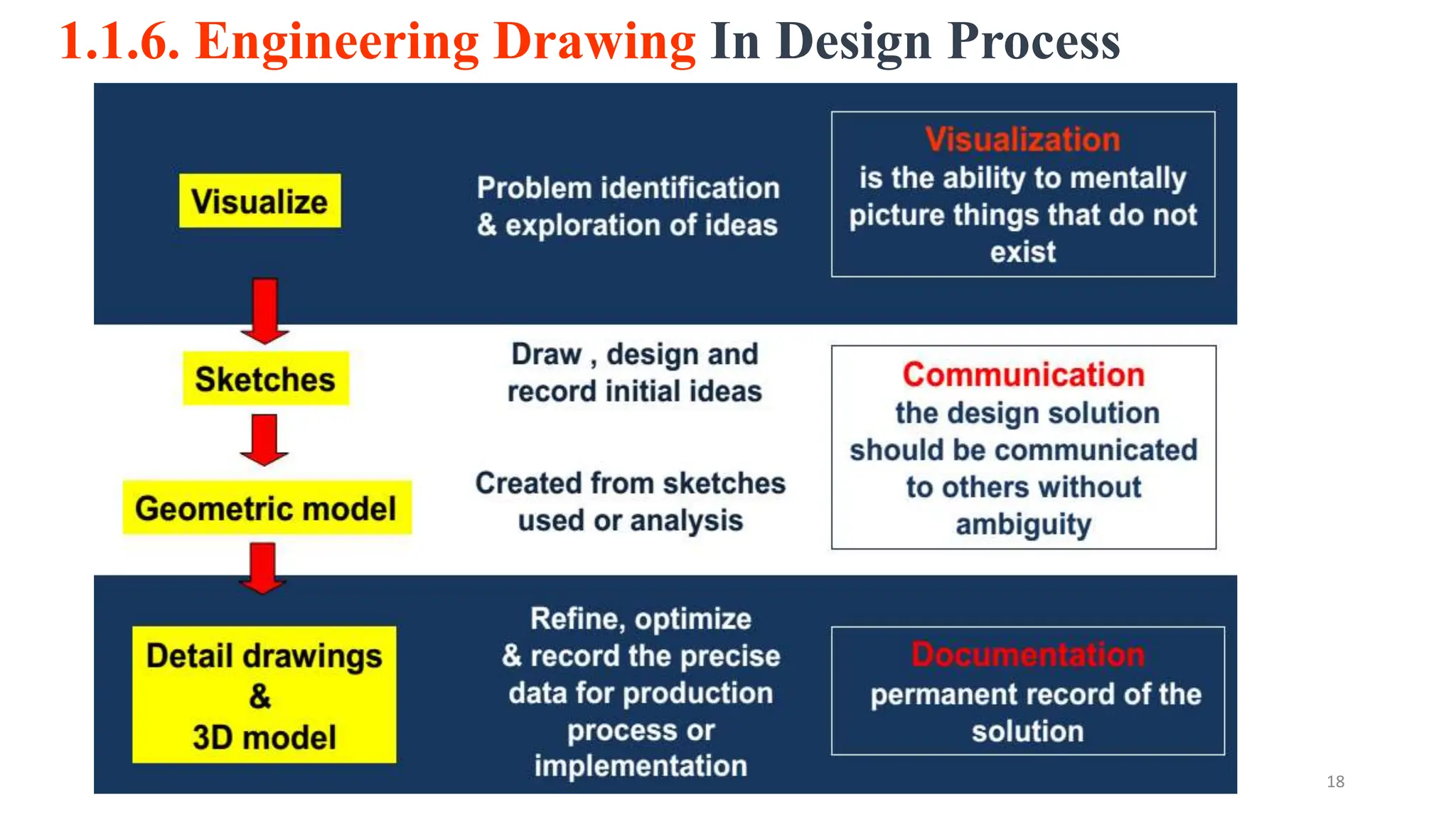
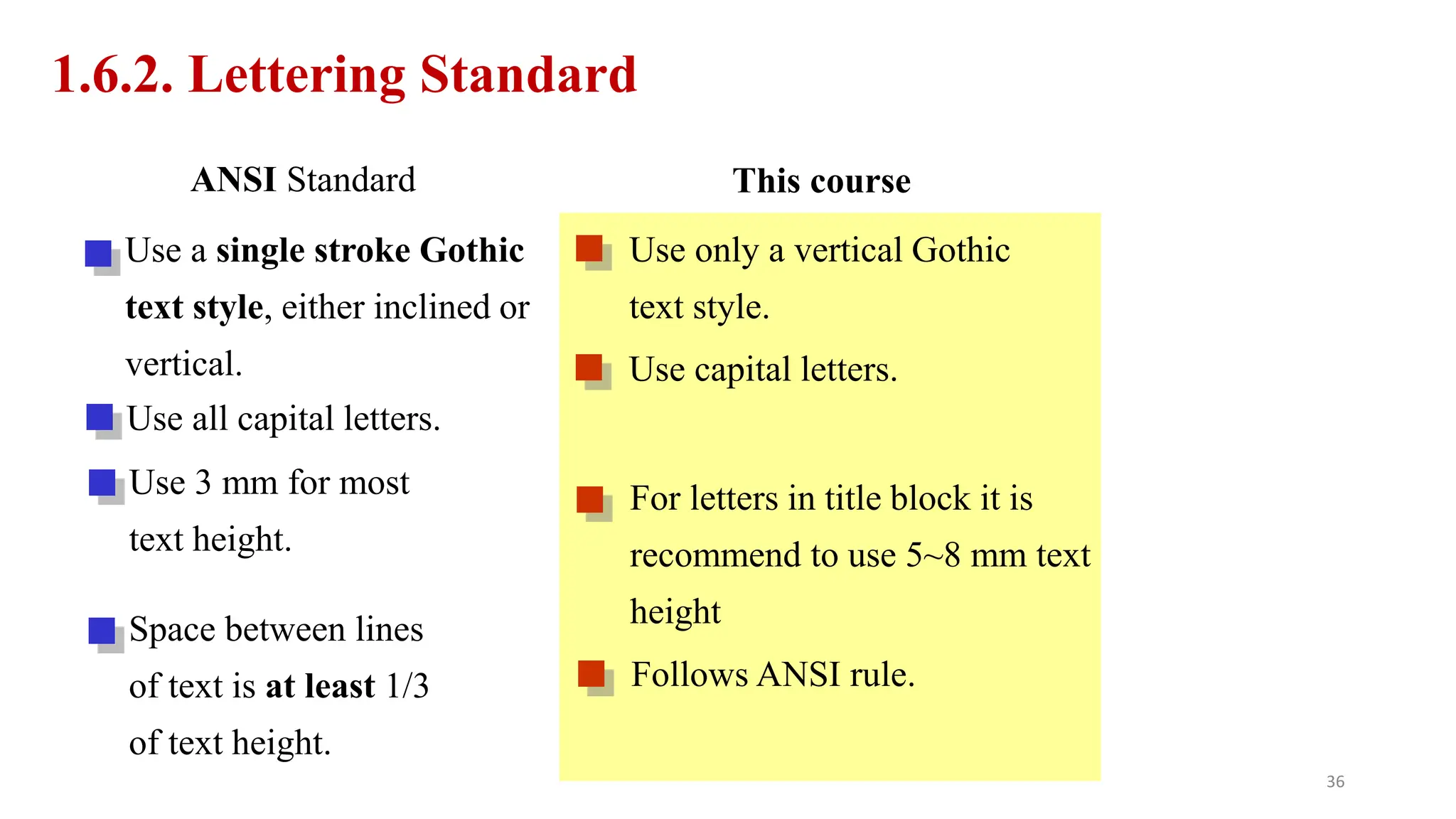
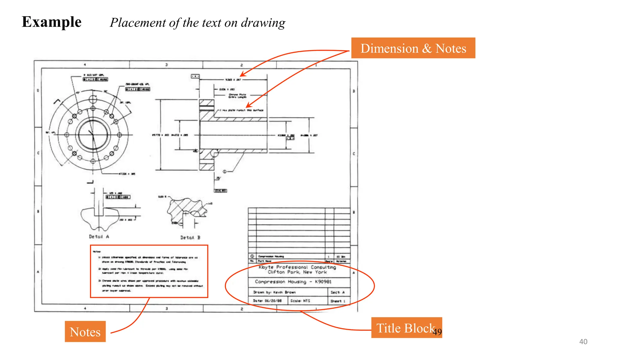
ADAMA SCIENCE AND TECHNOLOGY UNIVERSITY
SCHOOL OF MECHANICAL, CHEMICALAND MATERIAL ENGINEERING
DEPARTMENT OF MECHANICAL ENGINEERING
ENGINEERING DRAWING ; MEng1102
CHAPTER-1
INTRODUCTION TO ENGINEERING DRAWING
14/01/2024
CONTENTS
1. Introduction
2. Applications of Engineers Drawing
3. History Of Technical Drawing
4. Drawing Standards
5. Drawing Tools
6. Lettering
7. Lines And Their Types
8. Standards
Reference
1
Learning Objectives
 Able to define drawing and explain its advantage for technical
communication.
 Identify drawing instruments, able to use and properly handle them.
 Identify lettering standard and practice how to write.
 Explain the meaning of basic line types and their uses.
1
2
11
15
19
1. INTRODUCTION
1.1. Definitions: What is drawing?
A graphic representation of a real thing, an idea, or a proposed design
for later manufacturing or construction.
Graphics language uses as a way of communicating all necessary
information about an abstraction such as an idea or a concept.
This language is known as “drawing” or “drafting”
2
1. Try to write a description of this object.
2. Test someone attempt to make a sketch from your
description.
1.1.2. Effectiveness of Graphics Language
The word languages are inadequate for describing the size,
shape and features completely as well as concisely.
You can easily understand that …
3
1.1.3. Basic Elements of Engineering Drawing
Drawing as a Graphics language Word language
Line
types
Geometric
constructions
Lettering
Projection
methods
4
Cont.…
Engineering drawing are made up of graphics language and word language.
Graphics language
Describe a shape
(mainly).
Word language
Describe size, location and
specification of the object.
5
1.1.4. Graphic Language
• Graphic language in “engineering application” use lines to
represent the surfaces, edges and contours of objects.
• A drawing can be done by freehand, or using instruments or
computer methods.
6
A. Freehand drawing
• The lines are sketched without using instruments other than pencils
and erasers..
Example
7
B. Instrument drawing
• Instruments are used to draw straight lines, circles, and curves
concisely and accurately. Thus, the drawings are usually made to
scale.
Example
8
C. Computer drawing method
• The drawings are usually made by commercial software such as
AutoCAD, solid works and Catia etc.
Example
9
1.1.5. Types of Drawings
Artistic
Sketches
(Conceptual)
Diagrams
(Design)
Engineering Drawings
(Technical)
Drawing
Technical
Less technical More technical 10
11
A. Technical versus Artistic Drawing
 Technical drawing must communicate the same message to every
user or reader of the drawing, whereas an artistic drawing is usually
interpreted differently by everyone who sees it.
19
11
B. Sketch versus Engineering Drawing
•Sketch: made without drawing tools... Just pencil and paper. Scale is
approximate, not accurate, but the sketch should still look like the
object.
19
 Engineering Drawing: Made with drawing tools... Such as ruler, set
squares, protractor and compass. Scale should be accurate and the
drawing should be prepared carefully.
11
 Engineers: are people who use technical means to solve problems.
They design products, systems, devices, and structures to improve
our living conditions.
11
1.1.6. Engineering Drawing In Design Process
18
11
15
19
1.2. APPLICATIONS OF
ENGINEERS DRAWING
12
13
14
15
15
15
19
1.3. HISTORY OF TECHNICAL
DRAWING
1.3. History of Drawing:
Drawing is one of the oldest forms of communication, dating back
even further than the verbal communication.
Historically drawing is started by the caveman.
He uses it for communication to lead his day to day life.
16
 Egyptian hieroglyphics also play its own role for the development of
drawing.
 Leonardo da Vinci prepared mechanical drawings showing orthographic
views as we do now.
16
Cont.…
Then Industrial revolution is one of the milestones for the
development of drawing.
From time to time several rules and principles are developed to
utilize drawing as efficient as possible.
It is about 1749 in which the drawing with the current conventional
representations came into existence by Washington DC civil
engineers.
17
Cont.…
19
1.4. DRAWING STANDARDS
1.4.1. Drawing Sheet :
ISO standard size
c paper
20
Cont.…
21
1.4.2. Drawing paper:
• The following elements to be noticed over the format of our drawing
paper:
• Border line: it is the peripheral heaviest lines which enclose all drawings.
• Title Block: It is a box where all information about the drawing such as
drawn by, checked by, date, scale, title of drawing, drawing number and
company name are specified.
• Guide line: is the lightest line used to guide the height of alphabets.
22
105
23
1.4.3. Drawing Scales
Scale: is a ratio between the linear dimension(Length and size) of a drawn
representation of an object and the actual object.
24
 Designation of a scale consists of the word “SCALE” followed by the
indication of its ratio, as follows.
 SCALE 1:1 for full size
 SCALE X:1 (X > 1) for an enlargement scales
 SCALE 1:X (X > 1) for a reduction scales
25
1.5. DRAWING TOOLS
26
1.5.1. Drawing instruments:
 The preparation of technical drawing is
possible only through knowledge and skill in
the use of a variety of instruments.
 With the aid of knowledge, skill and practice
it is possible to bring perfection!
27
 Pencils: 2H or HB for thick line
4H for thin line
28
 DRAWING TOOLS
 T-Square
29
(Set-Square)
Cont….
 Protractor
 Compass
 Divider
Adhesive Tape
30
Cont….
• Sharpener
•
•
Circle Template Clean paper
31
Drawing instruments:
• The preparation of technical drawing is possible
only through knowledge and skill in the use of a
variety instruments
• With the aid of knowledge and skill practice it is
possible to bring perfection!
• Sharpen the lead with a sandpaper.
• Adjust the needle and the lead so that the tip of the needle extends
slightly more than the lead.
needle
1.5.2. Preparing the Compass
lead
32
Cont.….
Using the Compass
Start circle: Apply enough pressure to the needle, holding compass handle between thumb and
index fingers.
Complete circle: Revolve handle clockwise.
33
19
1.6. LETTERING
1.6.1. Lettering
• Lettering is used on drawings to give dimensions and other relevant information needed to
fully describe the item. To communicate nongraphic information.
• The lettering must be neat and legible in order to be easily read and understood.
35
1.6.2. Lettering Standard
ANSI Standard This course
Use a single stroke Gothic
text style, either inclined or
vertical.
Use all capital letters.
Use 3 mm for most
text height.
Space between lines
of text is at least 1/3
of text height.
Use only a vertical Gothic
text style.
Use capital letters.
For letters in title block it is
recommend to use 5~8 mm text
height
Follows ANSI rule.
36
Cont.….
38
Cont.….
 A drawing will be improved by good lettering.
 However, a good drawing will look sloppy and unprofessional if the lettering
is poorly done.
39
Example Placement of the text on drawing
Dimension & Notes
Notes Title Block
49
40
1.6.3. Basic Strokes
Straight Slanted Curved
Horizontal
1 1 2
3
Examples : Application of basic stroke
“I” letter “A” letter 1
2
3
4 5
6
“B” letter
50
41
Suggested Strokes Sequence
Straight and slanted line
letters
Curved line
letters
Curved line
letters &
Numerals
A. Upper-case letters & Numerals
51
42
The text’ s body height is about 2/3 the height of a capital
letter.
Suggested Strokes Sequence
B. Lower-case letters
43
Stroke Sequence
I L T F
E H V X W
44
O Q C G
5 7
45
j y f r
t
46
c o a b
d p q e
u
s
47
Leave the space between words equal to the space requires for writing
a letter “O”.
Example
1.6.4. Sentence Composition
ALL DIMENSIONS ARE IN
MILLIMETERS
O O O
OUNLESSOAND
OOTHERWISE SPECIFIED.
O
48
19
1.7. LINES AND THEIR TYPES
 To make your drawings easy to read, make the contrast between thick and
thin lines distinct.
 Thick lines(0.6 mm) should be twice the width of thin lines(0.3 mm).
1.7.1. LINES
48
49
1.7.2.
50
Cont.….
50
50
Example : Line conventions in engineering drawing
51
Example : Line conventions in engineering drawing
52
19
1.8. STANDARDS
Standards
Definition
• Drawing standards are set of rules that govern how technical drawings are
represented.
• Drawing standards are used so that drawings convey the same meaning to
everyone who reads them.
53
54
Freehand
Sketching
55
Straight Line
1. Hold the pencil naturally.
2. Spot the beginning and end points.
3. Swing the pencil back and forth between the points, barely
touching the paper until the direction is clearly established.
4. Draw the line firmly with a free and easy wrist-and-arm
motion
56
Horizontal line Vertical line
57
Nearly vertical
inclined line
Nearly horizontal
inclined line
58
Small Circle
Method 1 : Starting with a square
1. Lightly sketching the square and marking the mid-points.
2. Draw light diagonals and mark the estimated radius.
3. Draw the circle through the eight points.
Step 1 Step 2 Step 3
59
Method 2 : Starting with center line
Step 1 Step 2 Step 3
1. Lightly draw a center line.
2. Add light radial lines and mark the estimated radius.
3. Sketch the full circle.
Small Circle
60
1. Place the little finger (or pencil’ s tip) at the center as a pivot,
and set the pencil point at the radius-distance from the center.
2. Hold the hand in this position and rotate the paper.
Large Circle
61
Arc
Method 1 : Starting with a square
Method 2 : Starting with a center line
62
Quiz 1
63
Summary
 Engineers are people who use technical means to solve problems.
 Demonstrate the line weights (thickness) and types (dashed or solid) of lines used in the
alphabet of lines that specify meaning in technical drawings.
 List the advantages of several different drawing instruments and the qualities that distinguish
them.
 Add legible and quick notes and dimensions to sketches using uppercase letters drawn by
hand.
 Lay out a sheet and fill in the information in the title block using standard letter shapes.
 Drawing standards are set of rules that govern how technical drawings are represented.
References
63
Cecil H. Jensen, Jay D. Helsel, and Dennis Short, Engineering Drawing and Design, Aug 17, 2007.
David, Allan Low, Manual of Machine Drawing and Design Mechanical Drawing, Jun 1, 2006.
https://www.slideshare.net/shameem.mist/engineering-drawing
CHAPTER 1. Introduction to Engineering Drawing.pptx

CHAPTER 1. Introduction to Engineering Drawing.pptx

  • 1.
    ADAMA SCIENCE ANDTECHNOLOGY UNIVERSITY SCHOOL OF MECHANICAL, CHEMICALAND MATERIAL ENGINEERING DEPARTMENT OF MECHANICAL ENGINEERING ENGINEERING DRAWING ; MEng1102 CHAPTER-1 INTRODUCTION TO ENGINEERING DRAWING 14/01/2024
  • 2.
    CONTENTS 1. Introduction 2. Applicationsof Engineers Drawing 3. History Of Technical Drawing 4. Drawing Standards 5. Drawing Tools 6. Lettering 7. Lines And Their Types 8. Standards Reference 1
  • 3.
    Learning Objectives  Ableto define drawing and explain its advantage for technical communication.  Identify drawing instruments, able to use and properly handle them.  Identify lettering standard and practice how to write.  Explain the meaning of basic line types and their uses. 1
  • 4.
  • 5.
    1.1. Definitions: Whatis drawing? A graphic representation of a real thing, an idea, or a proposed design for later manufacturing or construction. Graphics language uses as a way of communicating all necessary information about an abstraction such as an idea or a concept. This language is known as “drawing” or “drafting” 2
  • 6.
    1. Try towrite a description of this object. 2. Test someone attempt to make a sketch from your description. 1.1.2. Effectiveness of Graphics Language The word languages are inadequate for describing the size, shape and features completely as well as concisely. You can easily understand that … 3
  • 7.
    1.1.3. Basic Elementsof Engineering Drawing Drawing as a Graphics language Word language Line types Geometric constructions Lettering Projection methods 4
  • 8.
    Cont.… Engineering drawing aremade up of graphics language and word language. Graphics language Describe a shape (mainly). Word language Describe size, location and specification of the object. 5
  • 9.
    1.1.4. Graphic Language •Graphic language in “engineering application” use lines to represent the surfaces, edges and contours of objects. • A drawing can be done by freehand, or using instruments or computer methods. 6
  • 10.
    A. Freehand drawing •The lines are sketched without using instruments other than pencils and erasers.. Example 7
  • 11.
    B. Instrument drawing •Instruments are used to draw straight lines, circles, and curves concisely and accurately. Thus, the drawings are usually made to scale. Example 8
  • 12.
    C. Computer drawingmethod • The drawings are usually made by commercial software such as AutoCAD, solid works and Catia etc. Example 9
  • 13.
    1.1.5. Types ofDrawings Artistic Sketches (Conceptual) Diagrams (Design) Engineering Drawings (Technical) Drawing Technical Less technical More technical 10
  • 14.
    11 A. Technical versusArtistic Drawing  Technical drawing must communicate the same message to every user or reader of the drawing, whereas an artistic drawing is usually interpreted differently by everyone who sees it. 19
  • 15.
    11 B. Sketch versusEngineering Drawing •Sketch: made without drawing tools... Just pencil and paper. Scale is approximate, not accurate, but the sketch should still look like the object. 19
  • 16.
     Engineering Drawing:Made with drawing tools... Such as ruler, set squares, protractor and compass. Scale should be accurate and the drawing should be prepared carefully. 11
  • 17.
     Engineers: arepeople who use technical means to solve problems. They design products, systems, devices, and structures to improve our living conditions. 11
  • 18.
    1.1.6. Engineering DrawingIn Design Process 18
  • 19.
  • 20.
  • 21.
  • 22.
  • 23.
  • 24.
  • 25.
    15 19 1.3. HISTORY OFTECHNICAL DRAWING
  • 26.
    1.3. History ofDrawing: Drawing is one of the oldest forms of communication, dating back even further than the verbal communication. Historically drawing is started by the caveman. He uses it for communication to lead his day to day life. 16
  • 27.
     Egyptian hieroglyphicsalso play its own role for the development of drawing.  Leonardo da Vinci prepared mechanical drawings showing orthographic views as we do now. 16 Cont.…
  • 28.
    Then Industrial revolutionis one of the milestones for the development of drawing. From time to time several rules and principles are developed to utilize drawing as efficient as possible. It is about 1749 in which the drawing with the current conventional representations came into existence by Washington DC civil engineers. 17 Cont.…
  • 29.
  • 30.
    1.4.1. Drawing Sheet: ISO standard size c paper 20
  • 31.
  • 32.
    1.4.2. Drawing paper: •The following elements to be noticed over the format of our drawing paper: • Border line: it is the peripheral heaviest lines which enclose all drawings. • Title Block: It is a box where all information about the drawing such as drawn by, checked by, date, scale, title of drawing, drawing number and company name are specified. • Guide line: is the lightest line used to guide the height of alphabets. 22
  • 33.
  • 34.
    1.4.3. Drawing Scales Scale:is a ratio between the linear dimension(Length and size) of a drawn representation of an object and the actual object. 24
  • 35.
     Designation ofa scale consists of the word “SCALE” followed by the indication of its ratio, as follows.  SCALE 1:1 for full size  SCALE X:1 (X > 1) for an enlargement scales  SCALE 1:X (X > 1) for a reduction scales 25
  • 36.
  • 37.
    1.5.1. Drawing instruments: The preparation of technical drawing is possible only through knowledge and skill in the use of a variety of instruments.  With the aid of knowledge, skill and practice it is possible to bring perfection! 27
  • 38.
     Pencils: 2Hor HB for thick line 4H for thin line 28
  • 39.
     DRAWING TOOLS T-Square 29 (Set-Square)
  • 40.
  • 41.
  • 42.
    Drawing instruments: • Thepreparation of technical drawing is possible only through knowledge and skill in the use of a variety instruments • With the aid of knowledge and skill practice it is possible to bring perfection! • Sharpen the lead with a sandpaper. • Adjust the needle and the lead so that the tip of the needle extends slightly more than the lead. needle 1.5.2. Preparing the Compass lead 32
  • 43.
    Cont.…. Using the Compass Startcircle: Apply enough pressure to the needle, holding compass handle between thumb and index fingers. Complete circle: Revolve handle clockwise. 33
  • 44.
  • 45.
    1.6.1. Lettering • Letteringis used on drawings to give dimensions and other relevant information needed to fully describe the item. To communicate nongraphic information. • The lettering must be neat and legible in order to be easily read and understood. 35
  • 46.
    1.6.2. Lettering Standard ANSIStandard This course Use a single stroke Gothic text style, either inclined or vertical. Use all capital letters. Use 3 mm for most text height. Space between lines of text is at least 1/3 of text height. Use only a vertical Gothic text style. Use capital letters. For letters in title block it is recommend to use 5~8 mm text height Follows ANSI rule. 36
  • 47.
  • 48.
    Cont.….  A drawingwill be improved by good lettering.  However, a good drawing will look sloppy and unprofessional if the lettering is poorly done. 39
  • 49.
    Example Placement ofthe text on drawing Dimension & Notes Notes Title Block 49 40
  • 50.
    1.6.3. Basic Strokes StraightSlanted Curved Horizontal 1 1 2 3 Examples : Application of basic stroke “I” letter “A” letter 1 2 3 4 5 6 “B” letter 50 41
  • 51.
    Suggested Strokes Sequence Straightand slanted line letters Curved line letters Curved line letters & Numerals A. Upper-case letters & Numerals 51 42
  • 52.
    The text’ sbody height is about 2/3 the height of a capital letter. Suggested Strokes Sequence B. Lower-case letters 43
  • 53.
    Stroke Sequence I LT F E H V X W 44
  • 54.
    O Q CG 5 7 45
  • 55.
    j y fr t 46
  • 56.
    c o ab d p q e u s 47
  • 57.
    Leave the spacebetween words equal to the space requires for writing a letter “O”. Example 1.6.4. Sentence Composition ALL DIMENSIONS ARE IN MILLIMETERS O O O OUNLESSOAND OOTHERWISE SPECIFIED. O 48
  • 58.
    19 1.7. LINES ANDTHEIR TYPES
  • 59.
     To makeyour drawings easy to read, make the contrast between thick and thin lines distinct.  Thick lines(0.6 mm) should be twice the width of thin lines(0.3 mm). 1.7.1. LINES 48
  • 60.
  • 61.
  • 62.
  • 63.
  • 64.
    Example : Lineconventions in engineering drawing 51
  • 65.
    Example : Lineconventions in engineering drawing 52
  • 66.
  • 67.
    Standards Definition • Drawing standardsare set of rules that govern how technical drawings are represented. • Drawing standards are used so that drawings convey the same meaning to everyone who reads them. 53
  • 68.
  • 69.
  • 70.
    Straight Line 1. Holdthe pencil naturally. 2. Spot the beginning and end points. 3. Swing the pencil back and forth between the points, barely touching the paper until the direction is clearly established. 4. Draw the line firmly with a free and easy wrist-and-arm motion 56
  • 71.
  • 72.
    Nearly vertical inclined line Nearlyhorizontal inclined line 58
  • 73.
    Small Circle Method 1: Starting with a square 1. Lightly sketching the square and marking the mid-points. 2. Draw light diagonals and mark the estimated radius. 3. Draw the circle through the eight points. Step 1 Step 2 Step 3 59
  • 74.
    Method 2 :Starting with center line Step 1 Step 2 Step 3 1. Lightly draw a center line. 2. Add light radial lines and mark the estimated radius. 3. Sketch the full circle. Small Circle 60
  • 75.
    1. Place thelittle finger (or pencil’ s tip) at the center as a pivot, and set the pencil point at the radius-distance from the center. 2. Hold the hand in this position and rotate the paper. Large Circle 61
  • 76.
    Arc Method 1 :Starting with a square Method 2 : Starting with a center line 62
  • 77.
  • 78.
    Summary  Engineers arepeople who use technical means to solve problems.  Demonstrate the line weights (thickness) and types (dashed or solid) of lines used in the alphabet of lines that specify meaning in technical drawings.  List the advantages of several different drawing instruments and the qualities that distinguish them.  Add legible and quick notes and dimensions to sketches using uppercase letters drawn by hand.  Lay out a sheet and fill in the information in the title block using standard letter shapes.  Drawing standards are set of rules that govern how technical drawings are represented.
  • 79.
    References 63 Cecil H. Jensen,Jay D. Helsel, and Dennis Short, Engineering Drawing and Design, Aug 17, 2007. David, Allan Low, Manual of Machine Drawing and Design Mechanical Drawing, Jun 1, 2006. https://www.slideshare.net/shameem.mist/engineering-drawing