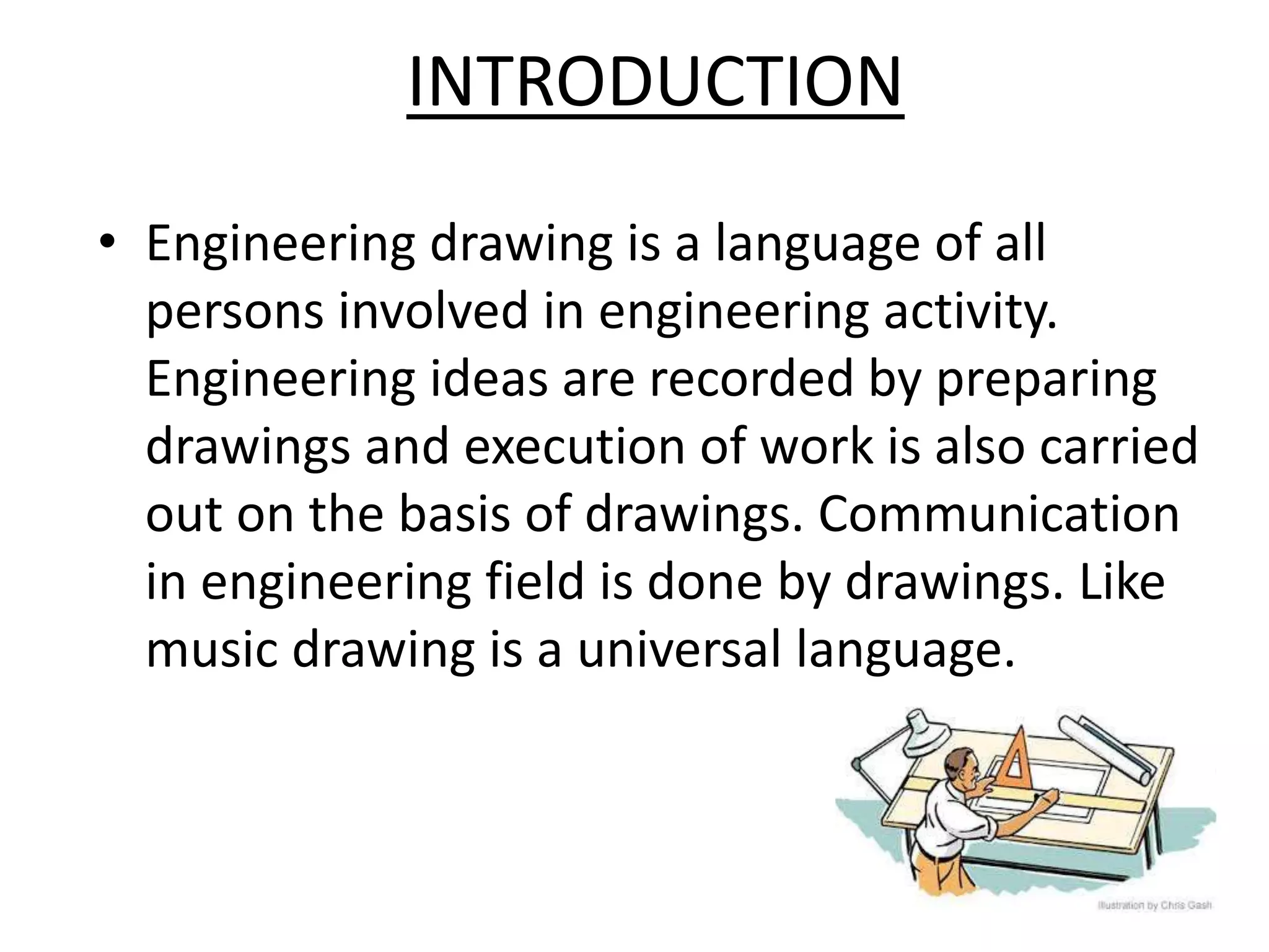
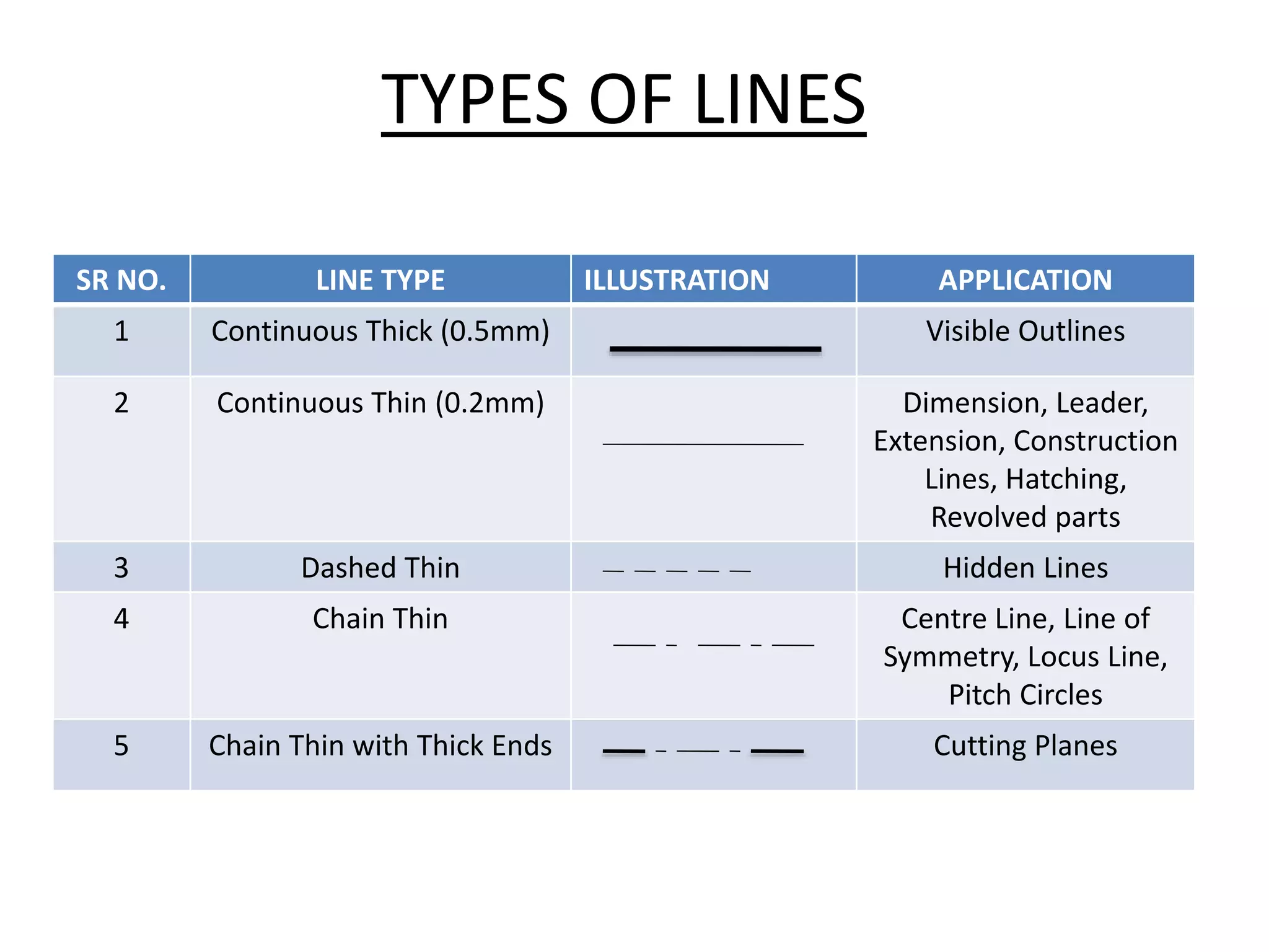
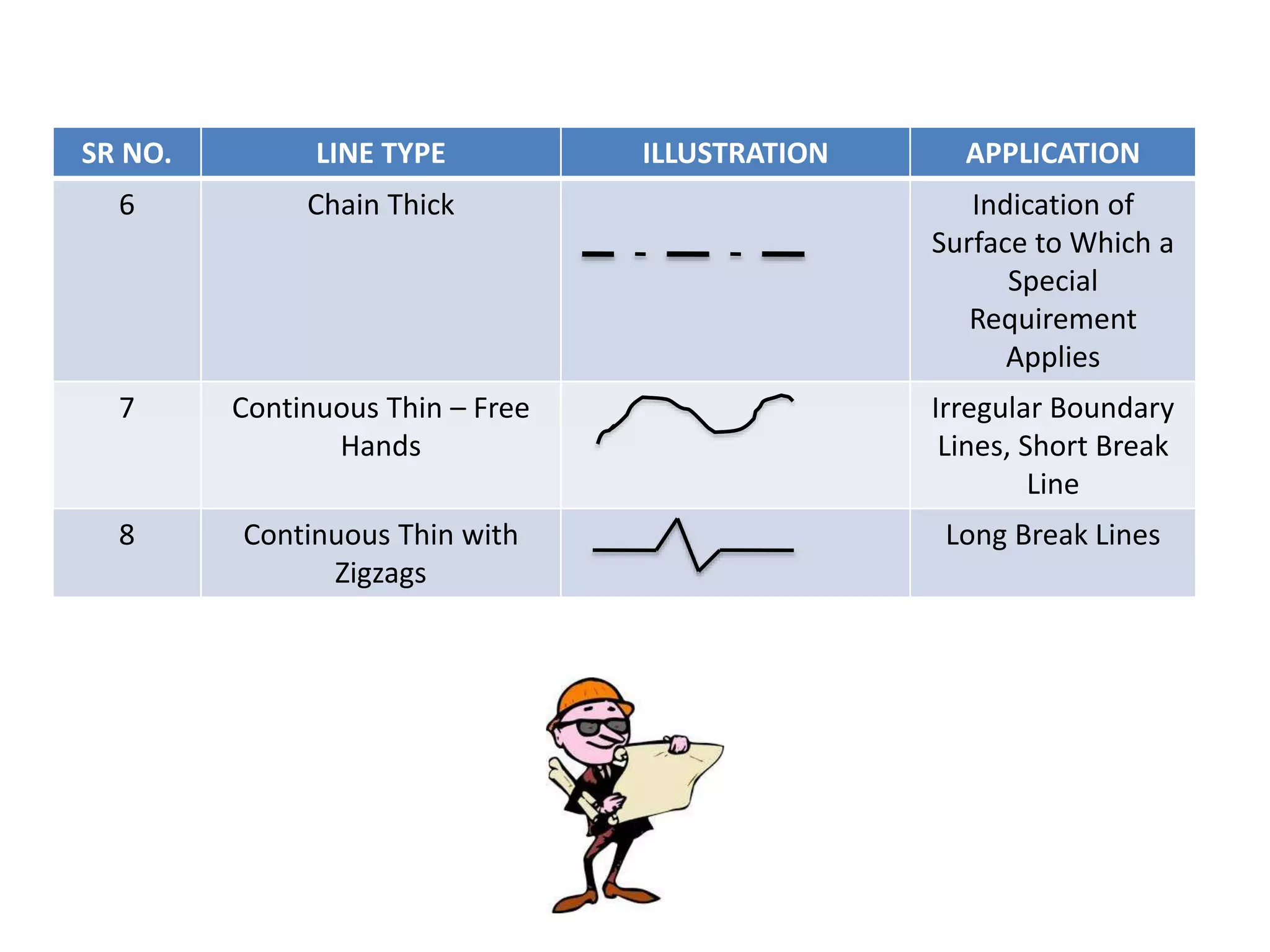
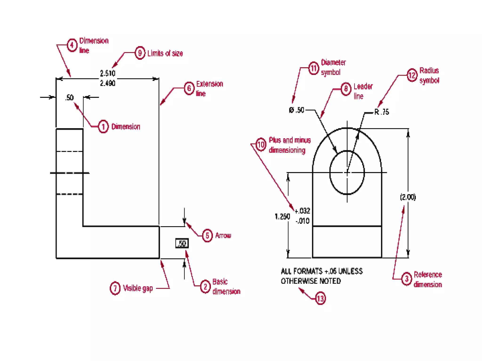
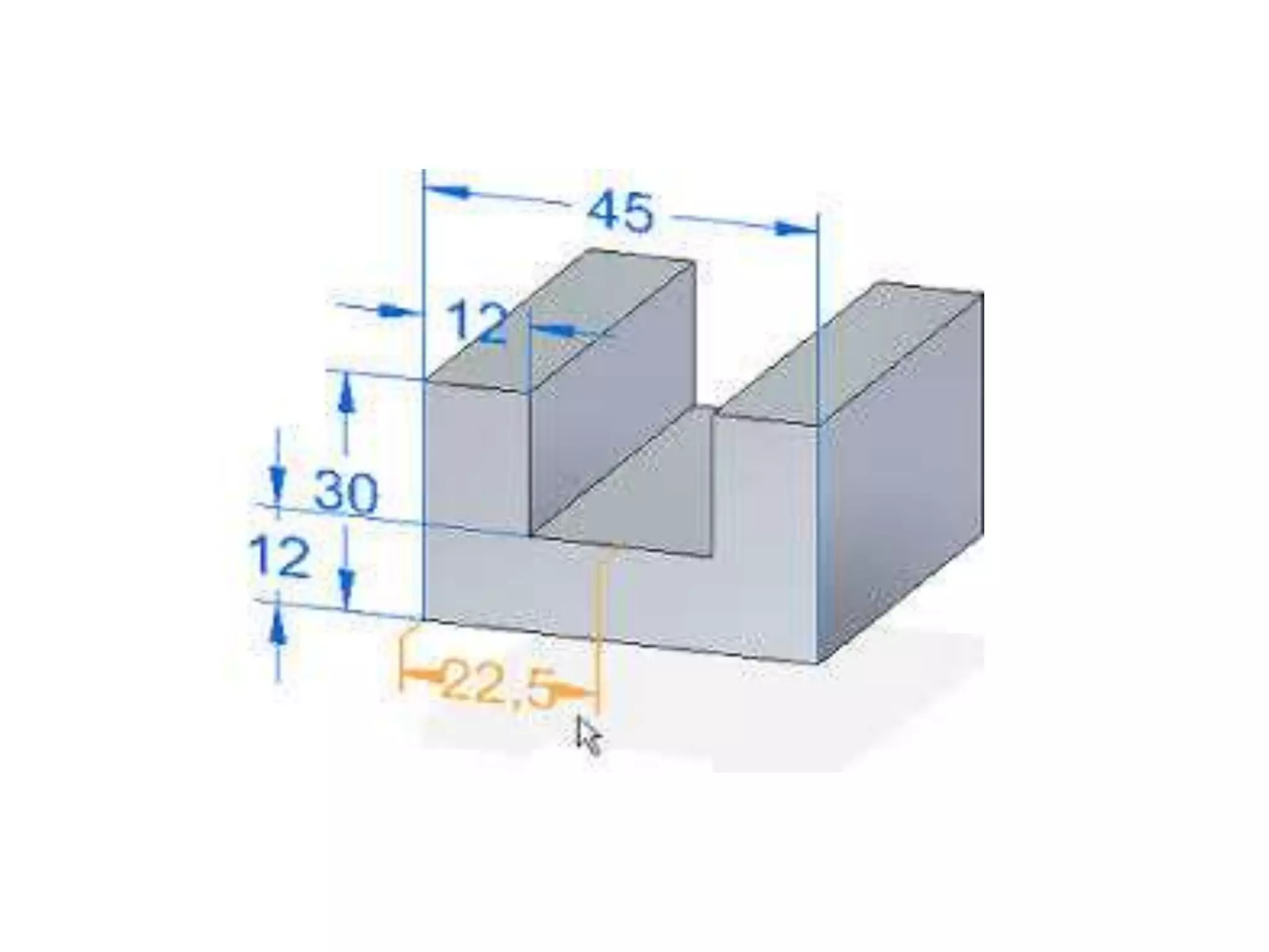
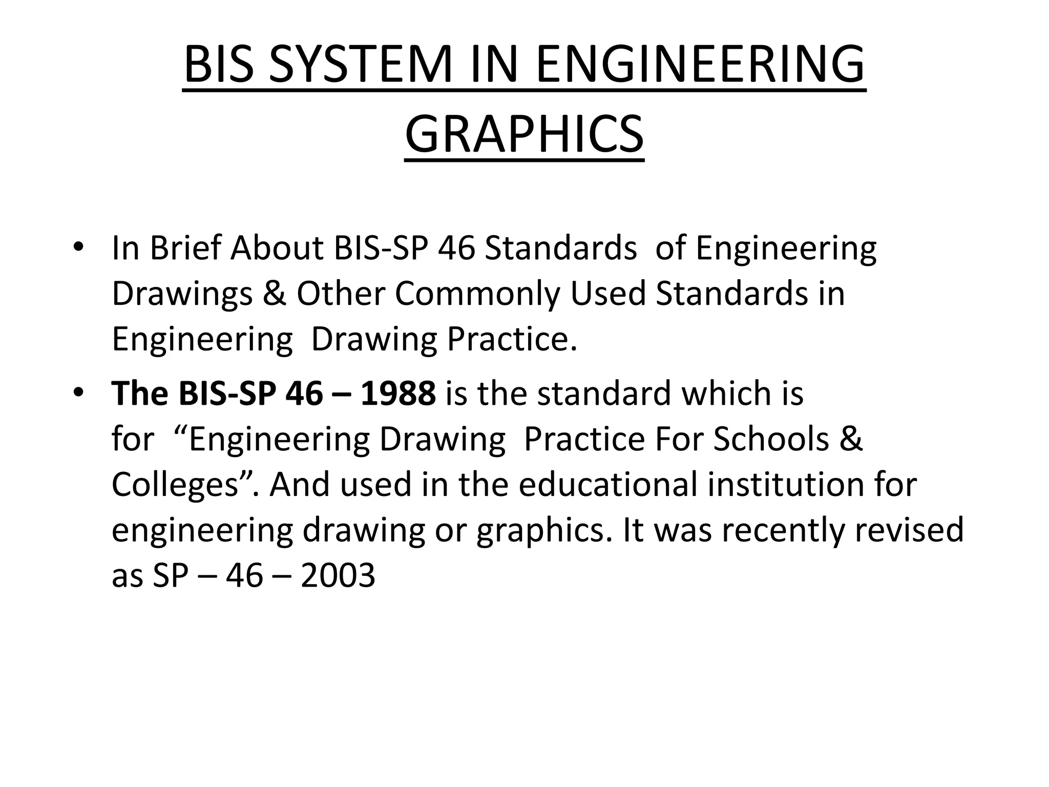
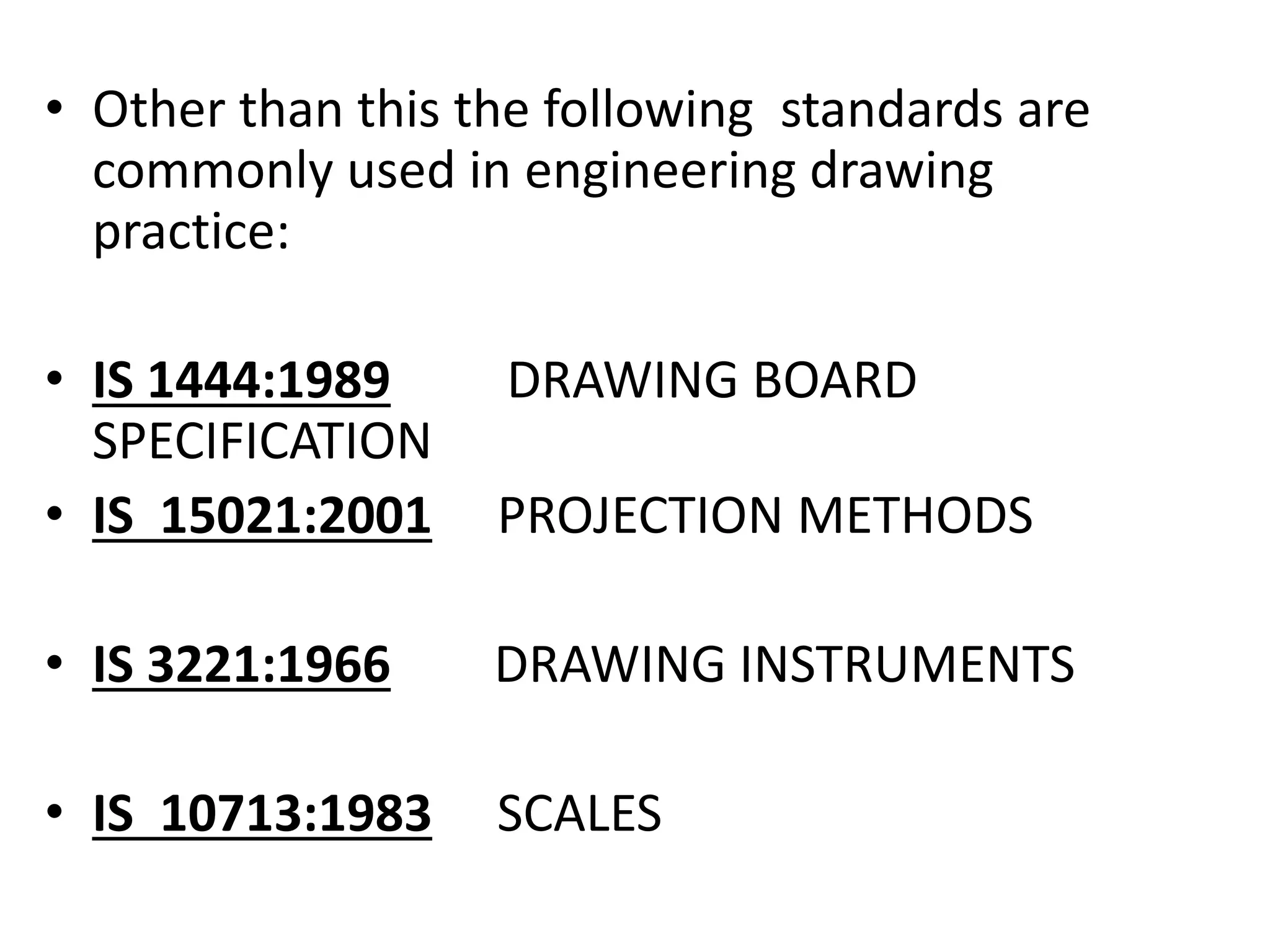
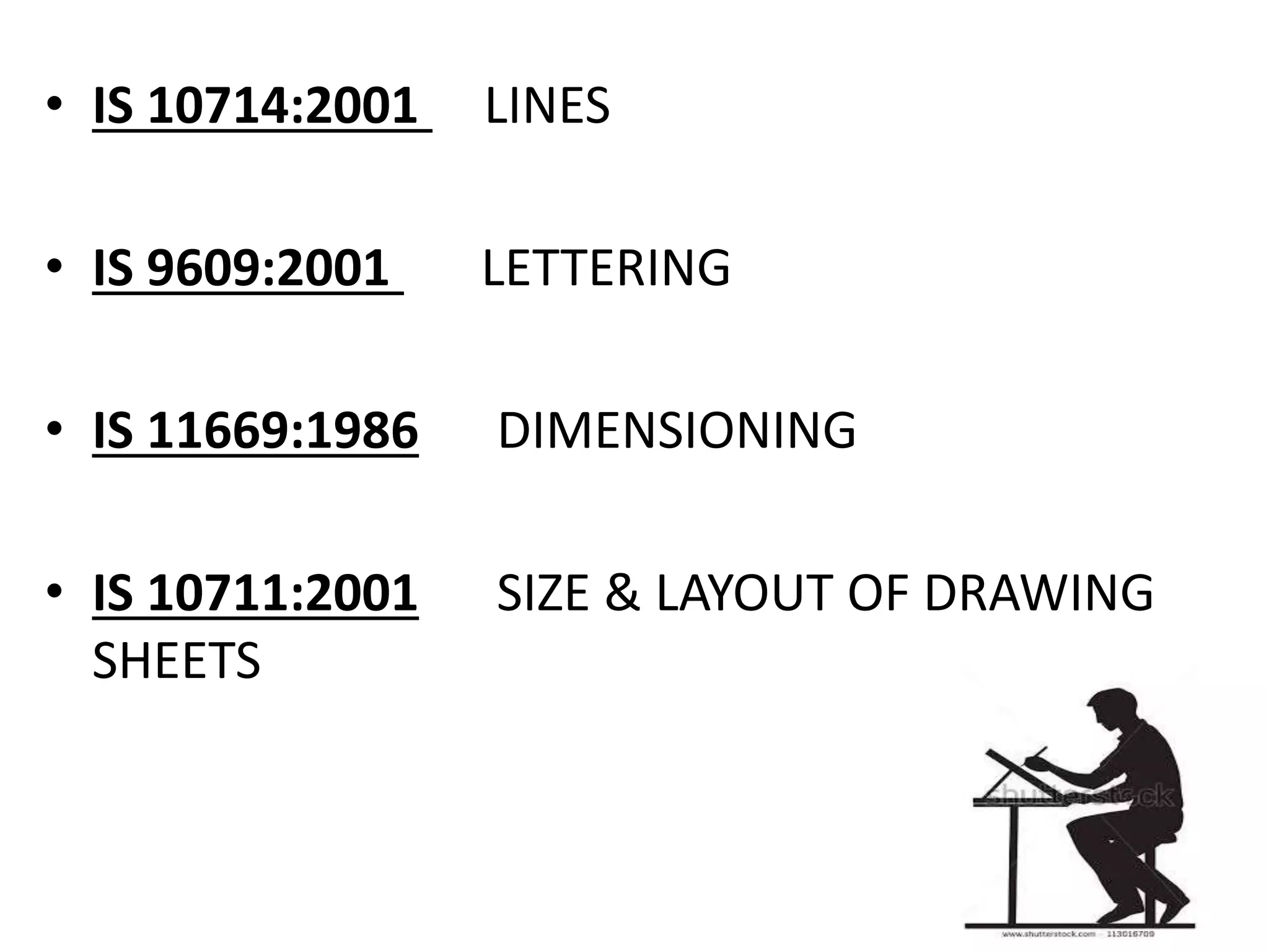
INTRODUCTION TO ENGINEERING GRAPHICS
Prepared BY : BE (IT)
Enrollment Number ID Number Name
160410116118 16BEITG002 Krunal Rathod
160410116031 16BEITG003 Shlok Gadre
160410116038 16BEITG004 Simran Gulani
160410116079 16BEITG005 Harsh Parmar
160410116032 16BEITG007 Mansi Gami
Guided By
Raghurajsinh Parmar
Info & Tech Dept. SVIT, VASAD - 041
INTRODUCTION
• Engineering drawing is a language of all
persons involved in engineering activity.
Engineering ideas are recorded by preparing
drawings and execution of work is also carried
out on the basis of drawings. Communication
in engineering field is done by drawings. Like
music drawing is a universal language.
HISTORY
• Throughout human history we have used
pictures to convey ideas, express ourselves,
present information, etc. Basically we have
used pictures to communicate. However
different people and cultures used different
types of pictures to communicate ideas.
This was a problem that faced engineers,
designers, builders, architects, etc. throughout
history. We didn't have one way of
communicating our ideas that everybody
understood.
• Gaspard Monge faced this problem when he
started as an Engineer in the French Military.
He devised a system that could be used to
communicate an object to anyone across the
world. This system is called Orthographic
Projection and was quickly adopted by army
engineers. However France was at war and
Monge's system was kept top secret. It wasn't
until many years later that Monge was
allowed to publish and teach his system.
Shortly this system spread across and
revolutionized world industry.
• Perspective drawing technique was invented
during
the Renaissance period (1300-1500)
• Descriptive geometry was invented by Gaspard
Monge in 1765
• Orthographic projection technique was invented
during
the Industrial Revolution period (1770-1850)
• 2-D CAD systems were developed in the 1980s
• 3-D CAD systems were developed in the 1990s
Gaspard Monge (1746-1818)
French mathematician and
father of descriptive geometry
DRAWING INSTRUMENTS
• To prepare engineering drawing, special
drawing instruments are required. It is
advisable to purchase simple and good quality
instruments rather than many ordinary
instruments. All those who are connected
with engineering activity should know the use
of drawing instruments, handling of
instruments and proper maintenance of
drawing instruments
Drawing board Mini drafter
Roller scale
Set square
Compass
Protractor
TYPES OF LINES
SR NO. LINE TYPE ILLUSTRATION APPLICATION
1 Continuous Thick (0.5mm) Visible Outlines
2 Continuous Thin (0.2mm) Dimension, Leader,
Extension, Construction
Lines, Hatching,
Revolved parts
3 Dashed Thin Hidden Lines
4 Chain Thin Centre Line, Line of
Symmetry, Locus Line,
Pitch Circles
5 Chain Thin with Thick Ends Cutting Planes
SR NO. LINE TYPE ILLUSTRATION APPLICATION
6 Chain Thick Indication of
Surface to Which a
Special
Requirement
Applies
7 Continuous Thin – Free
Hands
Irregular Boundary
Lines, Short Break
Line
8 Continuous Thin with
Zigzags
Long Break Lines
Dimensioning System
• General Rules for Dimensioning
 As far as possible, dimensions should be placed outside the
view.
 Dimensions should be taken from visible outlines rather than
from hidden lines.
 Dimensioning to the centre line should be avoided except
when the centre line passes through the centre of a hole.
 Each drawing should use the same unit of all dimensions, but
without showing the unit symbol.
 Each feature should be dimensioned once only on a drawing.
 No more dimensions than are necessary to define a part should be
shown on a drawing.
 No features of ma part should be defined by more than one
dimension in any one direction.
 Projections and dimension line should be drawn as a thin
continuous line.
 Projection lines should be drawn perpendicular to the feature being
dimensioned.
 Where necessary, they may be drawn obliquely, but parallel to each
other. However they must be in contact with the feature.
 Projection lines and dimension lines should not cross each other,
unless it is unavoidable.
 A centre line or the outline of a part should not be used as a
dimension line, but may be used in place of projection line.
BIS SYSTEM IN ENGINEERING
GRAPHICS
• In Brief About BIS-SP 46 Standards of Engineering
Drawings & Other Commonly Used Standards in
Engineering Drawing Practice.
• The BIS-SP 46 – 1988 is the standard which is
for “Engineering Drawing Practice For Schools &
Colleges”. And used in the educational institution for
engineering drawing or graphics. It was recently revised
as SP – 46 – 2003
• Other than this the following standards are
commonly used in engineering drawing
practice:
• IS 1444:1989 DRAWING BOARD
SPECIFICATION
• IS 15021:2001 PROJECTION METHODS
• IS 3221:1966 DRAWING INSTRUMENTS
• IS 10713:1983 SCALES
• IS 10714:2001 LINES
• IS 9609:2001 LETTERING
• IS 11669:1986 DIMENSIONING
• IS 10711:2001 SIZE & LAYOUT OF DRAWING
SHEETS
Introduction to engineering graphics

Introduction to engineering graphics

  • 1.
    INTRODUCTION TO ENGINEERINGGRAPHICS Prepared BY : BE (IT) Enrollment Number ID Number Name 160410116118 16BEITG002 Krunal Rathod 160410116031 16BEITG003 Shlok Gadre 160410116038 16BEITG004 Simran Gulani 160410116079 16BEITG005 Harsh Parmar 160410116032 16BEITG007 Mansi Gami Guided By Raghurajsinh Parmar Info & Tech Dept. SVIT, VASAD - 041
  • 2.
    INTRODUCTION • Engineering drawingis a language of all persons involved in engineering activity. Engineering ideas are recorded by preparing drawings and execution of work is also carried out on the basis of drawings. Communication in engineering field is done by drawings. Like music drawing is a universal language.
  • 3.
    HISTORY • Throughout humanhistory we have used pictures to convey ideas, express ourselves, present information, etc. Basically we have used pictures to communicate. However different people and cultures used different types of pictures to communicate ideas. This was a problem that faced engineers, designers, builders, architects, etc. throughout history. We didn't have one way of communicating our ideas that everybody understood.
  • 4.
    • Gaspard Mongefaced this problem when he started as an Engineer in the French Military. He devised a system that could be used to communicate an object to anyone across the world. This system is called Orthographic Projection and was quickly adopted by army engineers. However France was at war and Monge's system was kept top secret. It wasn't until many years later that Monge was allowed to publish and teach his system. Shortly this system spread across and revolutionized world industry.
  • 5.
    • Perspective drawingtechnique was invented during the Renaissance period (1300-1500) • Descriptive geometry was invented by Gaspard Monge in 1765 • Orthographic projection technique was invented during the Industrial Revolution period (1770-1850) • 2-D CAD systems were developed in the 1980s • 3-D CAD systems were developed in the 1990s
  • 6.
    Gaspard Monge (1746-1818) Frenchmathematician and father of descriptive geometry
  • 7.
    DRAWING INSTRUMENTS • Toprepare engineering drawing, special drawing instruments are required. It is advisable to purchase simple and good quality instruments rather than many ordinary instruments. All those who are connected with engineering activity should know the use of drawing instruments, handling of instruments and proper maintenance of drawing instruments
  • 8.
    Drawing board Minidrafter Roller scale
  • 9.
  • 10.
    TYPES OF LINES SRNO. LINE TYPE ILLUSTRATION APPLICATION 1 Continuous Thick (0.5mm) Visible Outlines 2 Continuous Thin (0.2mm) Dimension, Leader, Extension, Construction Lines, Hatching, Revolved parts 3 Dashed Thin Hidden Lines 4 Chain Thin Centre Line, Line of Symmetry, Locus Line, Pitch Circles 5 Chain Thin with Thick Ends Cutting Planes
  • 11.
    SR NO. LINETYPE ILLUSTRATION APPLICATION 6 Chain Thick Indication of Surface to Which a Special Requirement Applies 7 Continuous Thin – Free Hands Irregular Boundary Lines, Short Break Line 8 Continuous Thin with Zigzags Long Break Lines
  • 12.
    Dimensioning System • GeneralRules for Dimensioning  As far as possible, dimensions should be placed outside the view.  Dimensions should be taken from visible outlines rather than from hidden lines.  Dimensioning to the centre line should be avoided except when the centre line passes through the centre of a hole.  Each drawing should use the same unit of all dimensions, but without showing the unit symbol.
  • 15.
     Each featureshould be dimensioned once only on a drawing.  No more dimensions than are necessary to define a part should be shown on a drawing.  No features of ma part should be defined by more than one dimension in any one direction.  Projections and dimension line should be drawn as a thin continuous line.  Projection lines should be drawn perpendicular to the feature being dimensioned.  Where necessary, they may be drawn obliquely, but parallel to each other. However they must be in contact with the feature.  Projection lines and dimension lines should not cross each other, unless it is unavoidable.  A centre line or the outline of a part should not be used as a dimension line, but may be used in place of projection line.
  • 18.
    BIS SYSTEM INENGINEERING GRAPHICS • In Brief About BIS-SP 46 Standards of Engineering Drawings & Other Commonly Used Standards in Engineering Drawing Practice. • The BIS-SP 46 – 1988 is the standard which is for “Engineering Drawing Practice For Schools & Colleges”. And used in the educational institution for engineering drawing or graphics. It was recently revised as SP – 46 – 2003
  • 19.
    • Other thanthis the following standards are commonly used in engineering drawing practice: • IS 1444:1989 DRAWING BOARD SPECIFICATION • IS 15021:2001 PROJECTION METHODS • IS 3221:1966 DRAWING INSTRUMENTS • IS 10713:1983 SCALES
  • 20.
    • IS 10714:2001LINES • IS 9609:2001 LETTERING • IS 11669:1986 DIMENSIONING • IS 10711:2001 SIZE & LAYOUT OF DRAWING SHEETS