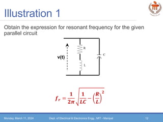
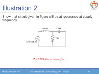
Basic Electrical Technology
[ELE 1051]
SINGLE PHASE AC CIRCUITS
L20 -Resonance
Monday, March 11, 2024 Dept. of Electrical & Electronics Engg., MIT - Manipal 1
Topics covered…
 Resonance in series RLC circuit
 What is half power frequency, bandwidth and quality factor in
series RLC circuit?
 Resonance in parallel circuits
Monday, March 11, 2024 Dept. of Electrical & Electronics Engg., MIT - Manipal 2
Series Resonance
Monday, March 11, 2024 Dept. of Electrical & Electronics Engg., MIT - Manipal
v(t), variable frequency
Z = R + 𝑗(XL~XC)
f
o
Z
R
fo
𝑋𝐶 = −
1
𝜔𝐶
𝒁 = 𝑹𝟐 + 𝝎𝑳 −
𝟏
𝝎𝑪
𝟐
R, X, Z
′𝒇𝟎 𝒊𝒔 𝒄𝒂𝒍𝒍𝒆𝒅 𝒕𝒉𝒆 𝒓𝒆𝒔𝒐𝒏𝒂𝒏𝒕 𝒇𝒓𝒆𝒒𝒖𝒆𝒏𝒄𝒚′
Z is inductive
Z is capacitive
Series Resonance
 When series RLC circuit is at resonance,
o Current is in phase with voltage
o Circuit power factor is unity
o 𝑋𝐿 = 𝑋𝐶
o 𝑍 = 𝑅
 Resonant frequency for a series RLC circuit is obtained as follows:
Monday, March 11, 2024 Dept. of Electrical & Electronics Engg., MIT - Manipal 4
𝑋𝐿 = 𝑋𝐶
𝜔0𝐿 =
1
𝜔0𝐶
𝒇𝟎 =
𝟏
𝟐𝝅 𝑳𝑪
𝒉𝒆𝒓𝒕𝒛
Imaginary p𝑎𝑟𝑡 𝑜𝑓 𝑍𝑒𝑞 = 0
v(t), variable frequency
Z = R + 𝑗(XL~XC)
Current vs. Frequency in RLC Series Circuit
Monday, March 11, 2024 Dept. of Electrical & Electronics Engg., MIT - Manipal 5
Variation of current with frequency
𝐼0 = 𝐼𝑚𝑎𝑥 =
𝑉
𝑟𝑚𝑠
𝑅
𝑰𝟎
𝒊
𝑰𝟎
𝟐
𝝎
𝝎𝟎
𝝎𝟏 𝝎𝟐
 Half Power Frequency
‘Frequency at which the power is half of
the power at resonant frequency’
𝑃𝑜𝑤𝑒𝑟 =
1
2
𝐼0
2
𝑅 =
𝐼0
2
2
𝑅
𝜔1 = 𝐿𝑜𝑤𝑒𝑟 ℎ𝑎𝑙𝑓 𝑝𝑜𝑤𝑒𝑟 𝑓𝑟𝑒𝑞𝑢𝑒𝑛𝑐𝑦
𝜔2 = 𝑈𝑝𝑝𝑒𝑟 ℎ𝑎𝑙𝑓 𝑝𝑜𝑤𝑒𝑟 𝑓𝑟𝑒𝑞𝑢𝑒𝑛𝑐𝑦
𝐴𝑡 𝜔1 𝑎𝑛𝑑 𝜔2, 𝐼 =
𝐼0
2
𝐁𝐚𝐧𝐝𝐰𝐢𝐝𝐭𝐡 = 𝛚𝟐 − 𝛚𝟏
In practice the curve of |𝐼| against ω is not symmetrical about the resonant frequency
Half Power Frequency
Monday, March 11, 2024 Dept. of Electrical & Electronics Engg., MIT - Manipal 6
𝐼𝑚𝑝𝑒𝑑𝑎𝑛𝑐𝑒 𝑎𝑡 𝜔1𝑎𝑛𝑑 𝜔2, |𝑍| =
𝑉0
𝐼0
2
= 2𝑅
Below Resonant frequency 𝜔0, 𝑋𝐶 > |𝑋𝐿| Above Resonant frequency 𝜔0, 𝑋𝐿 > |𝑋𝐶|
At 𝜔1,
𝑅2 + 𝑋𝐶 − 𝑋𝐿
2 = 2𝑅
𝑋𝐶 − 𝑋𝐿 = 𝑅
1
𝜔1𝐶
− 𝜔1𝐿 = R
𝝎𝟏 =
−𝑹
𝟐𝑳
+
𝑹
𝟐𝑳
𝟐
+
𝟏
𝑳𝑪
At 𝜔2,
𝑅2 + 𝑋𝐿 − 𝑋𝐶
2 = 2𝑅
𝑋𝐿 − 𝑋𝐶 = 𝑅
𝜔2𝐿 −
1
𝜔2𝐶
= R
𝝎𝟐 =
𝑹
𝟐𝑳
+
𝑹
𝟐𝑳
𝟐
+
𝟏
𝑳𝑪
𝝎𝟐 − 𝝎𝟐 =
𝑹
𝑳
𝝎𝟐𝝎𝟏 =
𝟏
𝑳𝑪
= 𝝎𝟎
𝟐
Quality Factor for series circuit
 At resonance, 𝑉𝐶 and 𝑉𝐿 can be very much greater than applied voltage
 High value of Q can lead to component damage
 Careful design necessary
 Larger the value of Q, more symmetrical the curve appears about the
resonant frequency
Monday, March 11, 2024 Dept. of Electrical & Electronics Engg., MIT - Manipal 7
𝑉𝐶 = 𝐼 𝑋𝐶 =
𝑉. 𝑋𝐶
𝑅2 + 𝑋𝐿 − 𝑋𝐶
2
At resonance, 𝑋𝐿 = 𝑋𝐶
𝑉𝐶 =
𝑉
𝑅
𝑋𝐶
𝑉𝐶 =
𝑉
𝜔0𝐶𝑅
= 𝑸𝑉
Q is termed the Q factor or voltage magnification
𝑸 =
𝟏
𝝎𝟎𝑪𝑹
=
𝝎𝟎𝑳
𝑹
=
𝟏
𝑹
𝑳
𝑪
𝑸 =
𝑹𝒆𝒔𝒐𝒏𝒂𝒏𝒕 𝒇𝒓𝒆𝒒𝒖𝒆𝒏𝒄𝒚
𝑩𝒂𝒏𝒅𝒘𝒊𝒅𝒕𝒉
Illustration 1
A circuit having a resistance of 4Ω and inductance of 0.5H and a
variable capacitance in series, is connected across a 100V,
50Hz supply. Calculate:
a) The capacitance to give resonance
b) The voltages across the inductor and the capacitor
c) The Q factor of the circuit
Monday, March 11, 2024 Dept. of Electrical & Electronics Engg., MIT - Manipal 8
Ans:
C = 20.3𝜇F
𝑉𝐶 = 𝑉𝐿 = 3930𝑉
Q = 39.3
Illustration 2
The bandwidth of a series resonant circuit is 500 Hz. If the
resonant frequency is 6000 Hz, what is the value of Q? If R =10
Ω, what is the value of the inductive reactance at resonance?
Calculate the inductance and capacitance of the circuit
Monday, March 11, 2024 Dept. of Electrical & Electronics Engg., MIT - Manipal 9
Ans:
Q = 12
𝑋𝐿 = 120Ω
L = 3.18mH; C = 0.22𝜇F
Resonance in parallel circuits
Steps to obtain the expression of resonant frequency in parallel circuits
o Obtain the net admittance of the circuit
o Equate the imaginary part (susceptance) to zero and obtain the expression of
𝜔𝑟
The expression for resonant frequency depends on circuit configuration
Monday, March 11, 2024 Dept. of Electrical & Electronics Engg., MIT - Manipal 10
Current vs. Frequency in parallel Circuits
 At resonance
o Impedance is maximum
o Resultant current minimum
Monday, March 11, 2024 Dept. of Electrical & Electronics Engg., MIT - Manipal 11
ωr
o
𝑰
𝝎
Illustration 1
Obtain the expression for resonant frequency for the given
parallel circuit
Monday, March 11, 2024 Dept. of Electrical & Electronics Engg., MIT - Manipal 12
𝒇𝒓 =
𝟏
𝟐𝝅
𝟏
𝑳𝑪
−
𝑹
𝑳
𝟐
Illustration 2
Show that circuit given in figure will be at resonance at supply
frequency
Monday, March 11, 2024 Dept. of Electrical & Electronics Engg., MIT - Manipal 13
vs=Cos(1.4t)
L=0.5H C=1F
5
Z = 0.099 at 𝜔 = 1.4 𝑟𝑎𝑑/𝑠𝑒𝑐

Basic Electric theory - Resonance.pptx

  • 1.
    Basic Electrical Technology [ELE1051] SINGLE PHASE AC CIRCUITS L20 -Resonance Monday, March 11, 2024 Dept. of Electrical & Electronics Engg., MIT - Manipal 1
  • 2.
    Topics covered…  Resonancein series RLC circuit  What is half power frequency, bandwidth and quality factor in series RLC circuit?  Resonance in parallel circuits Monday, March 11, 2024 Dept. of Electrical & Electronics Engg., MIT - Manipal 2
  • 3.
    Series Resonance Monday, March11, 2024 Dept. of Electrical & Electronics Engg., MIT - Manipal v(t), variable frequency Z = R + 𝑗(XL~XC) f o Z R fo 𝑋𝐶 = − 1 𝜔𝐶 𝒁 = 𝑹𝟐 + 𝝎𝑳 − 𝟏 𝝎𝑪 𝟐 R, X, Z ′𝒇𝟎 𝒊𝒔 𝒄𝒂𝒍𝒍𝒆𝒅 𝒕𝒉𝒆 𝒓𝒆𝒔𝒐𝒏𝒂𝒏𝒕 𝒇𝒓𝒆𝒒𝒖𝒆𝒏𝒄𝒚′ Z is inductive Z is capacitive
  • 4.
    Series Resonance  Whenseries RLC circuit is at resonance, o Current is in phase with voltage o Circuit power factor is unity o 𝑋𝐿 = 𝑋𝐶 o 𝑍 = 𝑅  Resonant frequency for a series RLC circuit is obtained as follows: Monday, March 11, 2024 Dept. of Electrical & Electronics Engg., MIT - Manipal 4 𝑋𝐿 = 𝑋𝐶 𝜔0𝐿 = 1 𝜔0𝐶 𝒇𝟎 = 𝟏 𝟐𝝅 𝑳𝑪 𝒉𝒆𝒓𝒕𝒛 Imaginary p𝑎𝑟𝑡 𝑜𝑓 𝑍𝑒𝑞 = 0 v(t), variable frequency Z = R + 𝑗(XL~XC)
  • 5.
    Current vs. Frequencyin RLC Series Circuit Monday, March 11, 2024 Dept. of Electrical & Electronics Engg., MIT - Manipal 5 Variation of current with frequency 𝐼0 = 𝐼𝑚𝑎𝑥 = 𝑉 𝑟𝑚𝑠 𝑅 𝑰𝟎 𝒊 𝑰𝟎 𝟐 𝝎 𝝎𝟎 𝝎𝟏 𝝎𝟐  Half Power Frequency ‘Frequency at which the power is half of the power at resonant frequency’ 𝑃𝑜𝑤𝑒𝑟 = 1 2 𝐼0 2 𝑅 = 𝐼0 2 2 𝑅 𝜔1 = 𝐿𝑜𝑤𝑒𝑟 ℎ𝑎𝑙𝑓 𝑝𝑜𝑤𝑒𝑟 𝑓𝑟𝑒𝑞𝑢𝑒𝑛𝑐𝑦 𝜔2 = 𝑈𝑝𝑝𝑒𝑟 ℎ𝑎𝑙𝑓 𝑝𝑜𝑤𝑒𝑟 𝑓𝑟𝑒𝑞𝑢𝑒𝑛𝑐𝑦 𝐴𝑡 𝜔1 𝑎𝑛𝑑 𝜔2, 𝐼 = 𝐼0 2 𝐁𝐚𝐧𝐝𝐰𝐢𝐝𝐭𝐡 = 𝛚𝟐 − 𝛚𝟏 In practice the curve of |𝐼| against ω is not symmetrical about the resonant frequency
  • 6.
    Half Power Frequency Monday,March 11, 2024 Dept. of Electrical & Electronics Engg., MIT - Manipal 6 𝐼𝑚𝑝𝑒𝑑𝑎𝑛𝑐𝑒 𝑎𝑡 𝜔1𝑎𝑛𝑑 𝜔2, |𝑍| = 𝑉0 𝐼0 2 = 2𝑅 Below Resonant frequency 𝜔0, 𝑋𝐶 > |𝑋𝐿| Above Resonant frequency 𝜔0, 𝑋𝐿 > |𝑋𝐶| At 𝜔1, 𝑅2 + 𝑋𝐶 − 𝑋𝐿 2 = 2𝑅 𝑋𝐶 − 𝑋𝐿 = 𝑅 1 𝜔1𝐶 − 𝜔1𝐿 = R 𝝎𝟏 = −𝑹 𝟐𝑳 + 𝑹 𝟐𝑳 𝟐 + 𝟏 𝑳𝑪 At 𝜔2, 𝑅2 + 𝑋𝐿 − 𝑋𝐶 2 = 2𝑅 𝑋𝐿 − 𝑋𝐶 = 𝑅 𝜔2𝐿 − 1 𝜔2𝐶 = R 𝝎𝟐 = 𝑹 𝟐𝑳 + 𝑹 𝟐𝑳 𝟐 + 𝟏 𝑳𝑪 𝝎𝟐 − 𝝎𝟐 = 𝑹 𝑳 𝝎𝟐𝝎𝟏 = 𝟏 𝑳𝑪 = 𝝎𝟎 𝟐
  • 7.
    Quality Factor forseries circuit  At resonance, 𝑉𝐶 and 𝑉𝐿 can be very much greater than applied voltage  High value of Q can lead to component damage  Careful design necessary  Larger the value of Q, more symmetrical the curve appears about the resonant frequency Monday, March 11, 2024 Dept. of Electrical & Electronics Engg., MIT - Manipal 7 𝑉𝐶 = 𝐼 𝑋𝐶 = 𝑉. 𝑋𝐶 𝑅2 + 𝑋𝐿 − 𝑋𝐶 2 At resonance, 𝑋𝐿 = 𝑋𝐶 𝑉𝐶 = 𝑉 𝑅 𝑋𝐶 𝑉𝐶 = 𝑉 𝜔0𝐶𝑅 = 𝑸𝑉 Q is termed the Q factor or voltage magnification 𝑸 = 𝟏 𝝎𝟎𝑪𝑹 = 𝝎𝟎𝑳 𝑹 = 𝟏 𝑹 𝑳 𝑪 𝑸 = 𝑹𝒆𝒔𝒐𝒏𝒂𝒏𝒕 𝒇𝒓𝒆𝒒𝒖𝒆𝒏𝒄𝒚 𝑩𝒂𝒏𝒅𝒘𝒊𝒅𝒕𝒉
  • 8.
    Illustration 1 A circuithaving a resistance of 4Ω and inductance of 0.5H and a variable capacitance in series, is connected across a 100V, 50Hz supply. Calculate: a) The capacitance to give resonance b) The voltages across the inductor and the capacitor c) The Q factor of the circuit Monday, March 11, 2024 Dept. of Electrical & Electronics Engg., MIT - Manipal 8 Ans: C = 20.3𝜇F 𝑉𝐶 = 𝑉𝐿 = 3930𝑉 Q = 39.3
  • 9.
    Illustration 2 The bandwidthof a series resonant circuit is 500 Hz. If the resonant frequency is 6000 Hz, what is the value of Q? If R =10 Ω, what is the value of the inductive reactance at resonance? Calculate the inductance and capacitance of the circuit Monday, March 11, 2024 Dept. of Electrical & Electronics Engg., MIT - Manipal 9 Ans: Q = 12 𝑋𝐿 = 120Ω L = 3.18mH; C = 0.22𝜇F
  • 10.
    Resonance in parallelcircuits Steps to obtain the expression of resonant frequency in parallel circuits o Obtain the net admittance of the circuit o Equate the imaginary part (susceptance) to zero and obtain the expression of 𝜔𝑟 The expression for resonant frequency depends on circuit configuration Monday, March 11, 2024 Dept. of Electrical & Electronics Engg., MIT - Manipal 10
  • 11.
    Current vs. Frequencyin parallel Circuits  At resonance o Impedance is maximum o Resultant current minimum Monday, March 11, 2024 Dept. of Electrical & Electronics Engg., MIT - Manipal 11 ωr o 𝑰 𝝎
  • 12.
    Illustration 1 Obtain theexpression for resonant frequency for the given parallel circuit Monday, March 11, 2024 Dept. of Electrical & Electronics Engg., MIT - Manipal 12 𝒇𝒓 = 𝟏 𝟐𝝅 𝟏 𝑳𝑪 − 𝑹 𝑳 𝟐
  • 13.
    Illustration 2 Show thatcircuit given in figure will be at resonance at supply frequency Monday, March 11, 2024 Dept. of Electrical & Electronics Engg., MIT - Manipal 13 vs=Cos(1.4t) L=0.5H C=1F 5 Z = 0.099 at 𝜔 = 1.4 𝑟𝑎𝑑/𝑠𝑒𝑐

Editor's Notes

  • #9 ‘Huges Electrical & Electronic Technology’, 10th edition Page No. 303, Example 14.1
  • #10 ‘Huges Electrical & Electronic Technology’, 10th edition Page No. 310, Example 14.3