Download to read offline

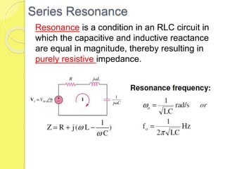
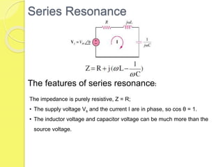
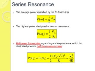

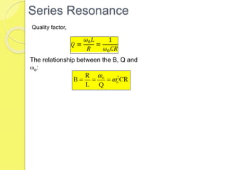


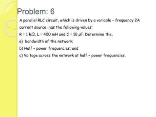


This document discusses series and parallel resonance in RLC circuits. Some key points: - Series resonance occurs when the capacitive and inductive reactances are equal, resulting in purely resistive impedance. The impedance is purely resistive (Z=R) and the current and voltage are in phase. - In parallel resonance, the impedance is maximum and the current is purely resistive. The impedance is purely resistive (Z=1/R) and the current and voltage are in phase. - Quality factor Q relates bandwidth to center frequency. As Q increases, bandwidth decreases. Q is proportional to center frequency and inversely proportional to bandwidth. The document provides several example problems