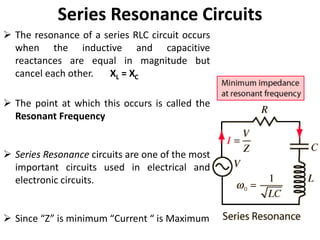
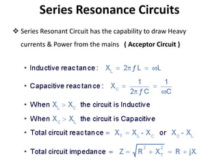
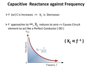
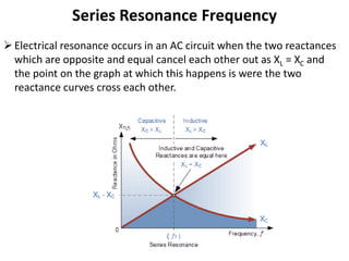
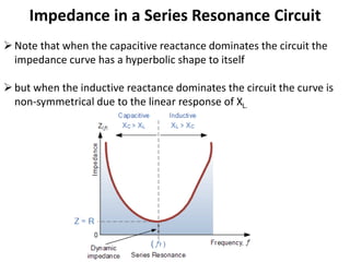
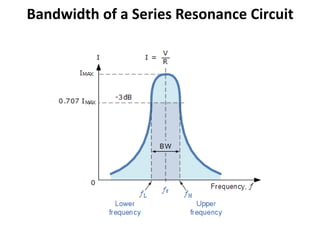
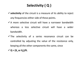
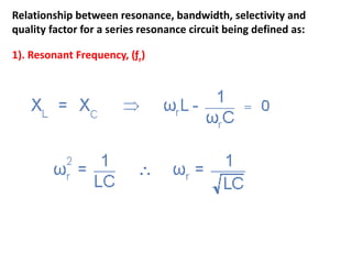
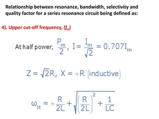
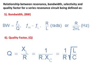
UNIT-III
RESONANCE & COUPLED CIRCUITS
This unit covers
 Series & Parallel Resonance
 Quality Factor
 Bandwidth
 Self & Mutual Inductance
 Coefficient of coupling
 Tuned Circuits – Single Tuned Circuits
Resonance
 When a Sinusoidal forcing function produces a response of
Maximum Amplitude.
An Ac Circuit comprising of R,L and C is said to be in Resonance
when the Applied voltage ( Source Voltage ) and the Source
Current are in phase ( i.e., Purely Resistive Circuit )
At Resonance P.F = Unity
The driving point impedance (or admittance) is completely
real when this condition exists.
Resonance in Electric Circuits
Series Resonance
Parallel Resonance
Series Resonance Circuits
 The resonance of a series RLC circuit occurs
when the inductive and capacitive
reactances are equal in magnitude but
cancel each other. XL = XC
 The point at which this occurs is called the
Resonant Frequency
 Series Resonance circuits are one of the most
important circuits used in electrical and
electronic circuits.
 Since “Z” is minimum “Current “ is Maximum
Series Resonance Circuits
 Series Resonant Circuit has the capability to draw Heavy
currents & Power from the mains ( Acceptor Circuit )
Uses of Series Resonance Circuits
AC mains filters
Noise filters
radio and television tuning circuits producing a very
selective tuning circuit for the receiving of the different
frequency channels.
Inductive Reactance against Frequency
F is Infinity XL is also Infinity => Circuit element Acts Like O.C
F is Zero XL is also Zero => Circuit Element Acts Like S.C
( XL ∝ ƒ )
Capacitive Reactance against Frequency
F (or) C is Increases => XC is Decreases
F approaches to ∞, XC reduces to zero => Causes Circuit
element to act like a Perfect Conductor ( 0Ω )
( XC ∝ ƒ -1 )
Series Resonance Frequency
Electrical resonance occurs in an AC circuit when the two reactances
which are opposite and equal cancel each other out as XL = XC and
the point on the graph at which this happens is were the two
reactance curves cross each other.
Series Resonance Frequency
In a series resonant circuit, the resonant frequency, ƒr point can be
calculated as follows.
Impedance in a Series Resonance Circuit
Note that when the capacitive reactance dominates the circuit the
impedance curve has a hyperbolic shape to itself
but when the inductive reactance dominates the circuit the curve is
non-symmetrical due to the linear response of XL.
Impedance in a Series Resonance Circuit
If the circuits impedance is at its minimum at resonance then
consequently, the circuits admittance must be at its maximum and
one of the characteristics of a series resonance circuit is that
admittance is very high.
But this can be a bad thing because a very low value of resistance at
resonance means that the circuits current may be dangerously high.
Impedance in a Series Resonance Circuit
If at resonance the two reactances are equal and
cancelling, the two voltages representing VL and VC must
also be opposite and equal in value thereby cancelling
each other out because with pure components the phasor
voltages are drawn at +90o and -90o respectively. Then in a
series resonance circuit VL = -VC therefore, V = VR.
Bandwidth of a Series Resonance Circuit
Selectivity ( Q )
 selectivity of the circuit is a measure of its ability to reject
any frequencies either side of these points.
 A more selective circuit will have a narrower bandwidth
whereas a less selective circuit will have a wider
bandwidth.
 The selectivity of a series resonance circuit can be
controlled by adjusting the value of the resistance only,
keeping all the other components the same, since
 Q = (XL or XC)/R.
Relationship between resonance, bandwidth, selectivity and
quality factor for a series resonance circuit being defined as:
1). Resonant Frequency, (ƒr)
Relationship between resonance, bandwidth, selectivity and
quality factor for a series resonance circuit being defined as:
2). Current, (I)
Relationship between resonance, bandwidth, selectivity and
quality factor for a series resonance circuit being defined as:
3). Lower cut-off frequency, (ƒL)
Relationship between resonance, bandwidth, selectivity and
quality factor for a series resonance circuit being defined as:
4). Upper cut-off frequency, (ƒH)
Relationship between resonance, bandwidth, selectivity and
quality factor for a series resonance circuit being defined as:
5). Bandwidth, (BW)
6). Quality Factor, (Q)
Problems

CT UNIT-III.pptx

  • 1.
  • 2.
    This unit covers Series & Parallel Resonance  Quality Factor  Bandwidth  Self & Mutual Inductance  Coefficient of coupling  Tuned Circuits – Single Tuned Circuits
  • 3.
    Resonance  When aSinusoidal forcing function produces a response of Maximum Amplitude. An Ac Circuit comprising of R,L and C is said to be in Resonance when the Applied voltage ( Source Voltage ) and the Source Current are in phase ( i.e., Purely Resistive Circuit ) At Resonance P.F = Unity The driving point impedance (or admittance) is completely real when this condition exists.
  • 4.
    Resonance in ElectricCircuits Series Resonance Parallel Resonance
  • 5.
    Series Resonance Circuits The resonance of a series RLC circuit occurs when the inductive and capacitive reactances are equal in magnitude but cancel each other. XL = XC  The point at which this occurs is called the Resonant Frequency  Series Resonance circuits are one of the most important circuits used in electrical and electronic circuits.  Since “Z” is minimum “Current “ is Maximum
  • 6.
    Series Resonance Circuits Series Resonant Circuit has the capability to draw Heavy currents & Power from the mains ( Acceptor Circuit )
  • 7.
    Uses of SeriesResonance Circuits AC mains filters Noise filters radio and television tuning circuits producing a very selective tuning circuit for the receiving of the different frequency channels.
  • 8.
    Inductive Reactance againstFrequency F is Infinity XL is also Infinity => Circuit element Acts Like O.C F is Zero XL is also Zero => Circuit Element Acts Like S.C ( XL ∝ ƒ )
  • 9.
    Capacitive Reactance againstFrequency F (or) C is Increases => XC is Decreases F approaches to ∞, XC reduces to zero => Causes Circuit element to act like a Perfect Conductor ( 0Ω ) ( XC ∝ ƒ -1 )
  • 10.
    Series Resonance Frequency Electricalresonance occurs in an AC circuit when the two reactances which are opposite and equal cancel each other out as XL = XC and the point on the graph at which this happens is were the two reactance curves cross each other.
  • 11.
    Series Resonance Frequency Ina series resonant circuit, the resonant frequency, ƒr point can be calculated as follows.
  • 12.
    Impedance in aSeries Resonance Circuit Note that when the capacitive reactance dominates the circuit the impedance curve has a hyperbolic shape to itself but when the inductive reactance dominates the circuit the curve is non-symmetrical due to the linear response of XL.
  • 13.
    Impedance in aSeries Resonance Circuit If the circuits impedance is at its minimum at resonance then consequently, the circuits admittance must be at its maximum and one of the characteristics of a series resonance circuit is that admittance is very high. But this can be a bad thing because a very low value of resistance at resonance means that the circuits current may be dangerously high.
  • 14.
    Impedance in aSeries Resonance Circuit If at resonance the two reactances are equal and cancelling, the two voltages representing VL and VC must also be opposite and equal in value thereby cancelling each other out because with pure components the phasor voltages are drawn at +90o and -90o respectively. Then in a series resonance circuit VL = -VC therefore, V = VR.
  • 15.
    Bandwidth of aSeries Resonance Circuit
  • 16.
    Selectivity ( Q)  selectivity of the circuit is a measure of its ability to reject any frequencies either side of these points.  A more selective circuit will have a narrower bandwidth whereas a less selective circuit will have a wider bandwidth.  The selectivity of a series resonance circuit can be controlled by adjusting the value of the resistance only, keeping all the other components the same, since  Q = (XL or XC)/R.
  • 17.
    Relationship between resonance,bandwidth, selectivity and quality factor for a series resonance circuit being defined as: 1). Resonant Frequency, (ƒr)
  • 18.
    Relationship between resonance,bandwidth, selectivity and quality factor for a series resonance circuit being defined as: 2). Current, (I)
  • 19.
    Relationship between resonance,bandwidth, selectivity and quality factor for a series resonance circuit being defined as: 3). Lower cut-off frequency, (ƒL)
  • 20.
    Relationship between resonance,bandwidth, selectivity and quality factor for a series resonance circuit being defined as: 4). Upper cut-off frequency, (ƒH)
  • 21.
    Relationship between resonance,bandwidth, selectivity and quality factor for a series resonance circuit being defined as: 5). Bandwidth, (BW) 6). Quality Factor, (Q)
  • 22.