Advantages of PLC
Less wiring.
Wiring between devices and relay contacts are
done in the PLC program.
Easier and faster to make changes.
Trouble shooting aids make programming
easier and reduce downtime.
Reliable components make these likely to
operate for years before failure.
INTRODUCTION TO PLC
3.
Definition of PLC
APLC is a digital operating electronic apparatus which uses a
programmable memory for internal storage of instruction for
implementing specific function such as logic, sequencing,
timing, counting and arithmetic to control through analog
or digital input/output modules various types of machines or
process.
4.
Consider somethingas simple as a switch that
turns on a light. In this system with a flick of the
switch the light would turn on or off. Beyond that
though there is no more control. If the switch has
been flipped, then you would need to buy a timer
and do some rewiring. So it is time, labor and
money for any little change.
Now consider the same device with a PLC in the
middle. The switch is fed as an input into the PLC
and the light is controlled by a PLC output.
Implementing a delay in this system is easy since
all that needs to be changed is the program in the
PLC to use a delay timer.
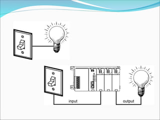
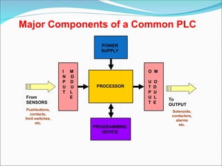
Major Components ofa Common PLC
PROCESSOR
POWER
SUPPLY
I M
N O
P D
U U
T L
E
O M
U O
T D
P U
U L
T E
PROGRAMMING
DEVICE
From
SENSORS
Pushbuttons,
contacts,
limit switches,
etc.
To
OUTPUT
Solenoids,
contactors,
alarms
etc.
8.
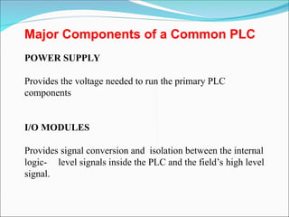
Major Components ofa Common PLC
POWER SUPPLY
Provides the voltage needed to run the primary PLC
components
I/O MODULES
Provides signal conversion and isolation between the internal
logic- level signals inside the PLC and the field’s high level
signal.
9.
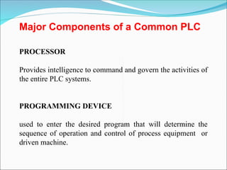
Major Components ofa Common PLC
PROCESSOR
Provides intelligence to command and govern the activities of
the entire PLC systems.
PROGRAMMING DEVICE
used to enter the desired program that will determine the
sequence of operation and control of process equipment or
driven machine.
10.
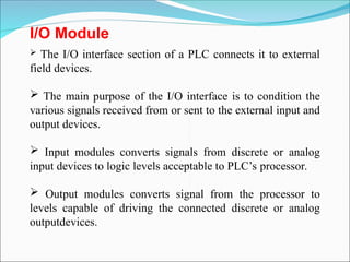
I/O Module
TheI/O interface section of a PLC connects it to external
field devices.
The main purpose of the I/O interface is to condition the
various signals received from or sent to the external input and
output devices.
Input modules converts signals from discrete or analog
input devices to logic levels acceptable to PLC’s processor.
Output modules converts signal from the processor to
levels capable of driving the connected discrete or analog
outputdevices.
11.
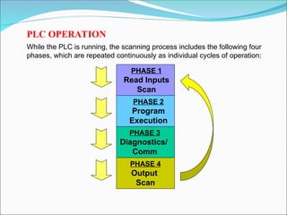
While the PLCis running, the scanning process includes the following four
phases, which are repeated continuously as individual cycles of operation:
PHASE 2
Program
Execution
PHASE 3
Diagnostics/
Comm
PHASE 4
Output
Scan
PHASE 1
Read Inputs
Scan
PLC OPERATION
12.
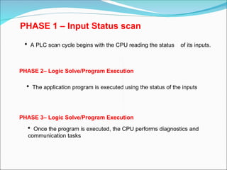
PHASE 1 –Input Status scan
A PLC scan cycle begins with the CPU reading the status of its inputs.
PHASE 2– Logic Solve/Program Execution
The application program is executed using the status of the inputs
PHASE 3– Logic Solve/Program Execution
Once the program is executed, the CPU performs diagnostics and
communication tasks
13.
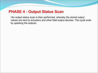
PHASE 4 -Output Status Scan
•An output status scan is then performed, whereby the stored output
values are sent to actuators and other field output devices. The cycle ends
by updating the outputs.
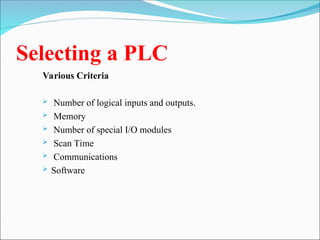
Selecting a PLC
VariousCriteria
Number of logical inputs and outputs.
Memory
Number of special I/O modules
Scan Time
Communications
Software
16.
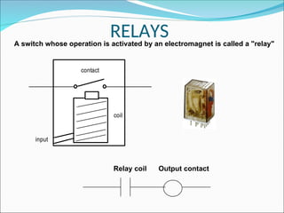
RELAYS
A switch whoseoperation is activated by an electromagnet is called a "relay"
contact
coil
input
Relay coil Output contact
17.
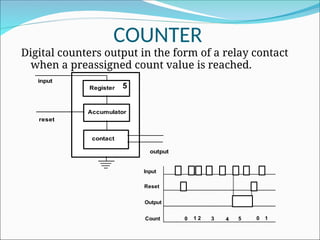
COUNTER
Digital counters outputin the form of a relay contact
when a preassigned count value is reached.
Register
Accumulator
contact
input
reset
output
Input
Reset
Output
Count 0 1 2 3 4 5 0 1
5
18.
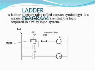
LADDER
DIAGRAM
A ladder diagram(also called contact symbology) is a
means of graphically representing the logic
required in a relay logic system.
A
R1
PB1 PB2
R1
R1
start emergency stop
Rail
Rung
20.
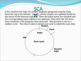
SCA
N
begin
Input
Output
Resolve
logic
Idle
A PLC resolvesthe logic of a ladder diagram (program) rung by rung,
from the top to the bottom. Usually, all the outputs are updated based on
the status of the internal registers. Then the input states are checked and
the corresponding input registers are updated. Only after the I/Os have
been resolved, is the program then executed. This process is run in a
endless cycle. The time it takes to finish one cycle is called the scan time.
Scan cycle
21.
PLC INSTRUCTIONS
1) Relay,
2)Timer and counter,
3) Program control,
4) Arithmetic,
5) Data manipulation,
6) Data transfer, and
7) Others, such as sequencers.
22.
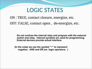
LOGIC STATES
ON :TRUE, contact closure, energize, etc.
OFF: FALSE, contact open , de-energize, etc.
(In the notes we use the symbol "~" to represent
negation. AND and OR are logic operators. )
Do not confuse the internal relay and program with the external
switch and relay. Internal symbols are used for programming.
External devices provide actual interface.
23.
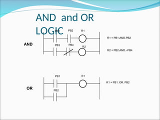
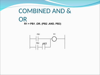
AND and OR
LOGIC
PB1R1
PB2
R2
R1 = PB1.AND.PB2
R2 = PB2.AND.~PB4
PB3 PB4
PB1 R1
PB2
R1 = PB1 .OR. PB2
AND
OR
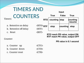
TIMERS AND
COUNTERS
Timers:
a. Retentiveon delay -(RTO)-
b. Retentive off delay -(RTF)-
c. Reset -(RST)-
Counter:
a. Counter up -(CTU)-
b. Counter down -(CTD)-
c. Counter reset -(CTR)-
RTO counting stop counting
resume
RTF stop counting stop
True False True
Input
RTO reach PR value, output ON
RTF reach PR value, output OFF
PR value in 0.1 second
26.
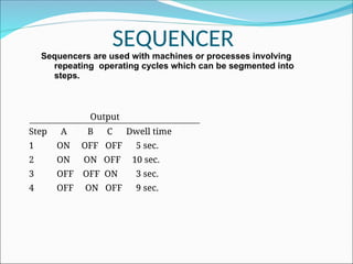
SEQUENCER
Sequencers are usedwith machines or processes involving
repeating operating cycles which can be segmented into
steps.
Output
Step A B C Dwell time
1 ON OFF OFF 5 sec.
2 ON ON OFF 10 sec.
3 OFF OFF ON 3 sec.
4 OFF ON OFF 9 sec.
27.
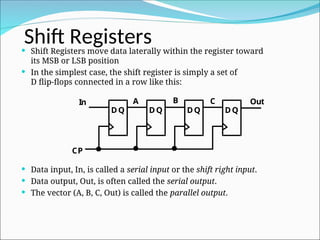
Shift Registers
ShiftRegisters move data laterally within the register toward
its MSB or LSB position
In the simplest case, the shift register is simply a set of
D flip-flops connected in a row like this:
Data input, In, is called a serial input or the shift right input.
Data output, Out, is often called the serial output.
The vector (A, B, C, Out) is called the parallel output.
DQ
DQ
DQ
DQ
In
CP
A B C Out
28.
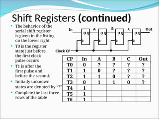
Shift Registers (continued)
The behavior of the
serial shift register
is given in the listing
on the lower right
T0 is the register
state just before
the first clock
pulse occurs
T1 is after the
first pulse and
before the second.
Initially unknown
states are denoted by “?”
Complete the last three
rows of the table
D Q
D Q
D Q
D Q
In
Clock CP
A B C Out
CP In A B C Out
T0 0 ? ? ? ?
T1 1 0 ? ? ?
T2 1 1 0 ? ?
T3 0 1 1 0 ?
T4 1
T5 1
T6 1
29.
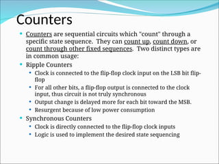
Counters aresequential circuits which "count" through a
specific state sequence. They can count up, count down, or
count through other fixed sequences. Two distinct types are
in common usage:
Ripple Counters
Clock is connected to the flip-flop clock input on the LSB bit flip-
flop
For all other bits, a flip-flop output is connected to the clock
input, thus circuit is not truly synchronous
Output change is delayed more for each bit toward the MSB.
Resurgent because of low power consumption
Synchronous Counters
Clock is directly connected to the flip-flop clock inputs
Logic is used to implement the desired state sequencing
Counters
30.
30
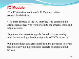
I/O Module
• TheI/O interface section of a PLC connects it to
external field devices.
• The main purpose of the I/O interface is to condition the
various signals received from or sent to the external input and
output devices.
• Input modules converts signals from discrete or analog
input devices to logic levels acceptable to PLC’s processor.
• Output modules converts signal from the processor to levels
capable of driving the connected discrete or analog output
devices.
31.
31
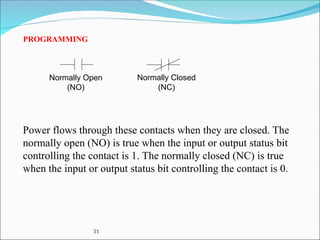
PROGRAMMING
Normally Open
(NO)
Normally Closed
(NC)
Powerflows through these contacts when they are closed. The
normally open (NO) is true when the input or output status bit
controlling the contact is 1. The normally closed (NC) is true
when the input or output status bit controlling the contact is 0.
32.
32
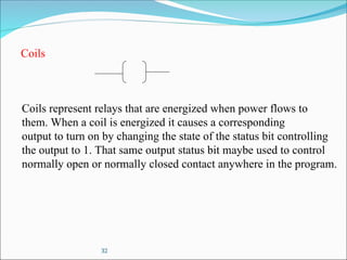
Coils
Coils represent relaysthat are energized when power flows to
them. When a coil is energized it causes a corresponding
output to turn on by changing the state of the status bit controlling
the output to 1. That same output status bit maybe used to control
normally open or normally closed contact anywhere in the program.
33.
33
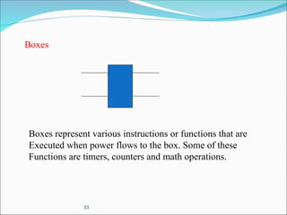
Boxes
Boxes represent variousinstructions or functions that are
Executed when power flows to the box. Some of these
Functions are timers, counters and math operations.
34.
34
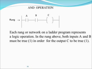
AND OPERATION
Each rungor network on a ladder program represents
a logic operation. In the rung above, both inputs A and B
must be true (1) in order for the output C to be true (1).
Rung
A B C
35.
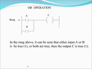
35
OR OPERATION
In therung above, it can be seen that either input A or B
is be true (1), or both are true, then the output C is true (1).
Rung
A
B
C
36.
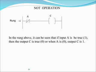
36
NOT OPERATION
In therung above, it can be seen that if input A is be true (1),
then the output C is true (0) or when A is (0), output C is 1.
Rung
A C