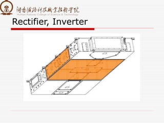
The document summarizes information about a traction converter, including:
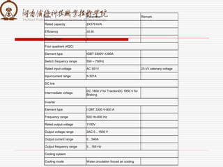
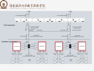
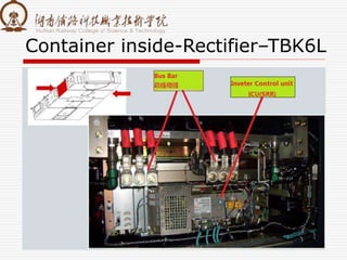
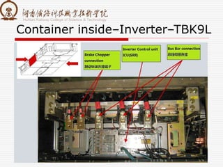
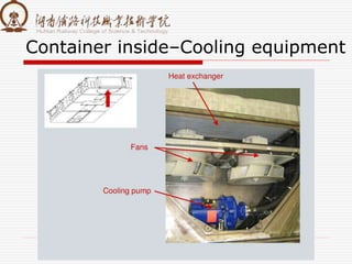
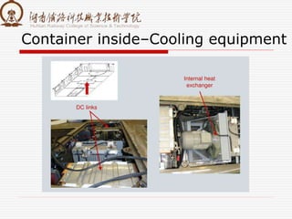
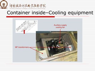
1. It is composed of a rectifier, middle DC link, and inverter.
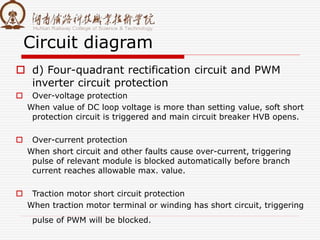
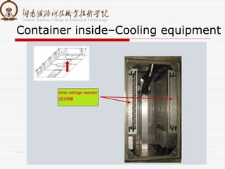
2. It provides over-voltage, over-current, and short-circuit protection for the traction motor.
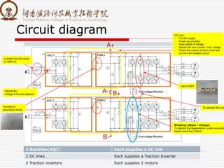
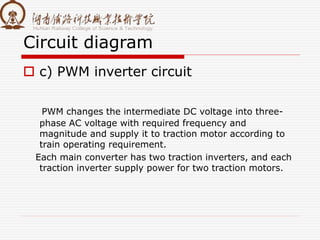
3. Key components include a four-quadrant rectification circuit to convert AC to DC, an intermediate supporting capacitor to buffer voltage, and a PWM inverter circuit to convert DC to variable frequency AC for the traction motors.