Download to read offline
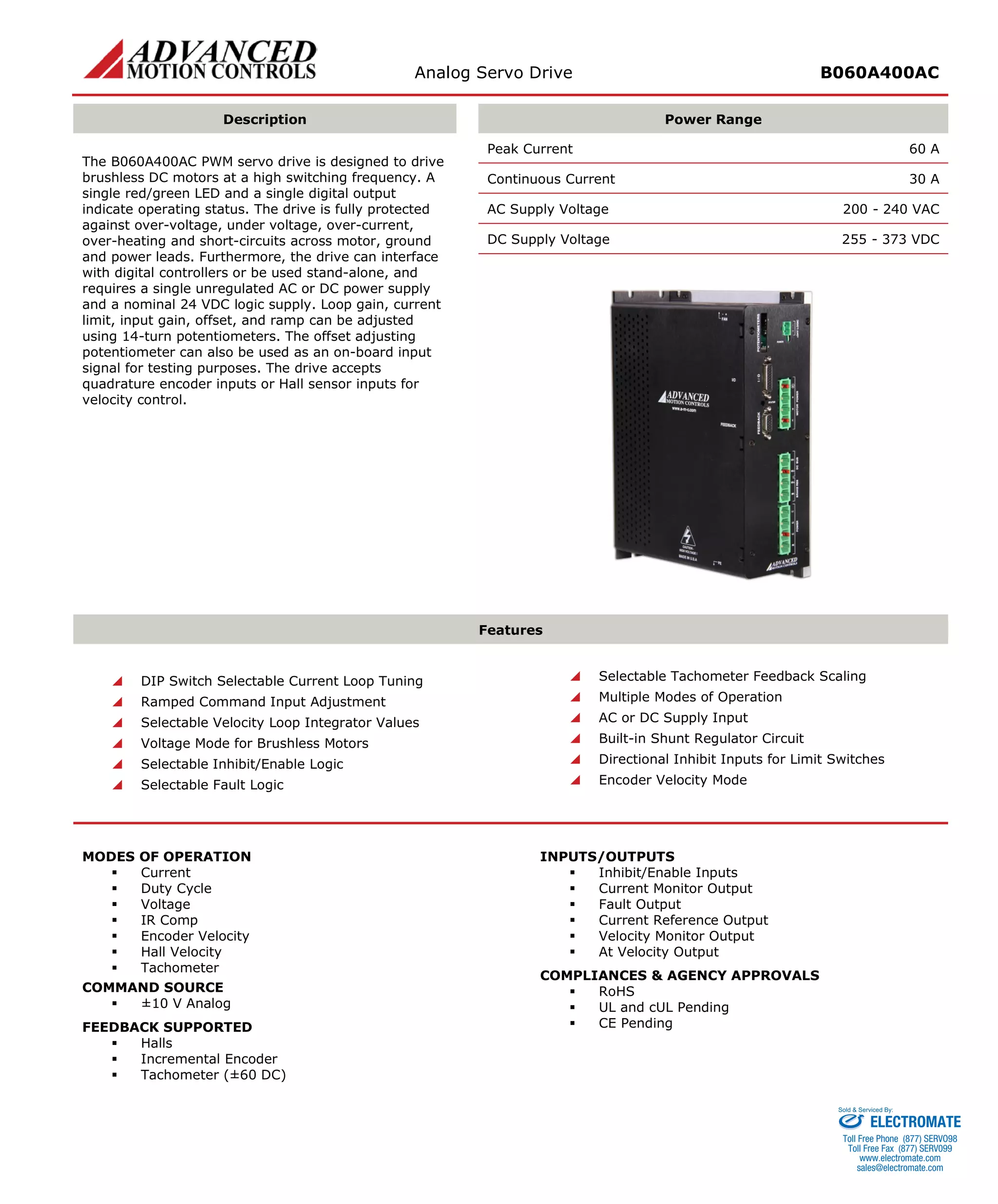
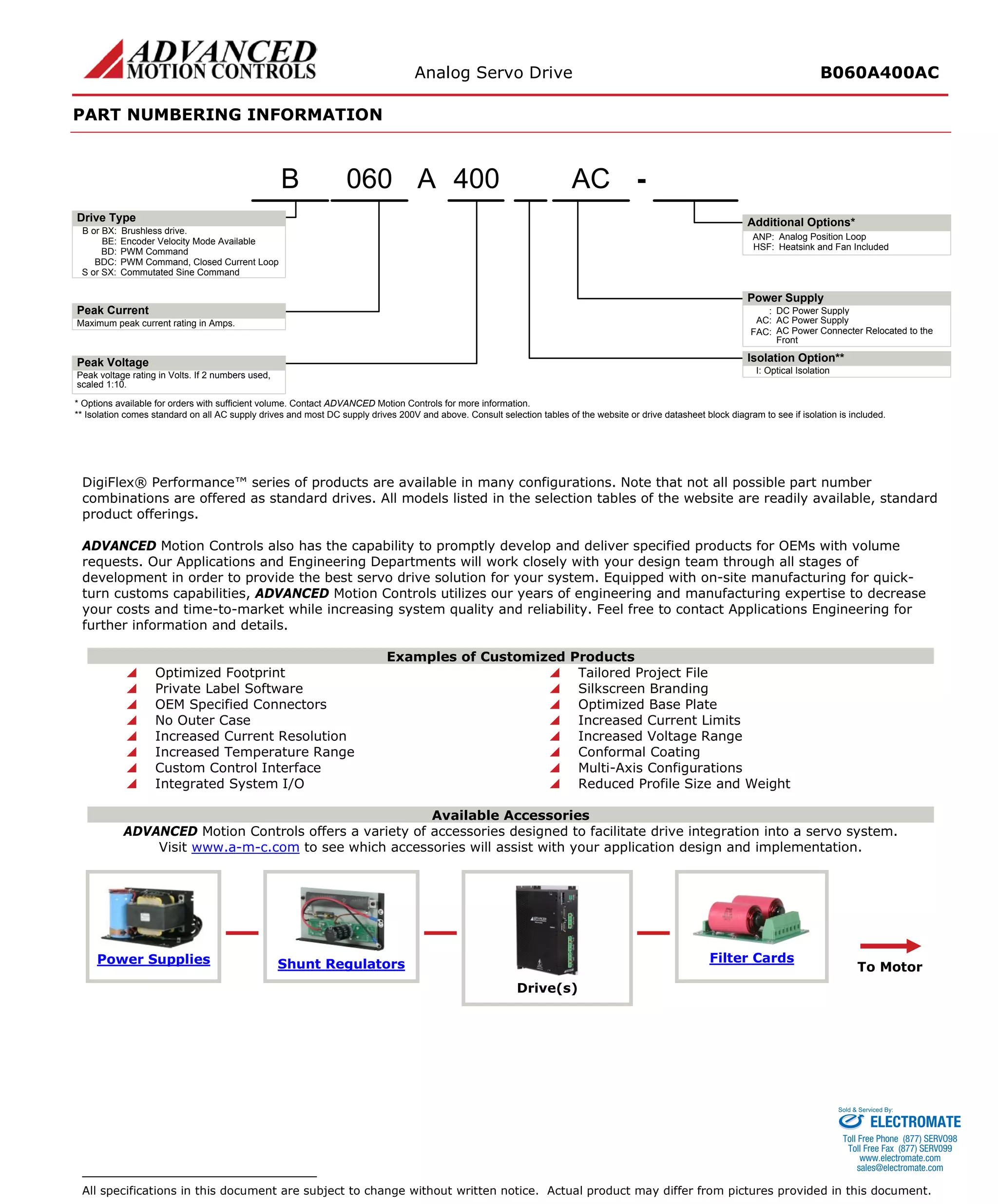

The document describes the Analog Servo Drive B060A400AC, which is designed to drive brushless DC motors at high switching frequencies. It can interface with digital controllers or operate standalone, accepting various feedback types. It has multiple operating modes and protections, and can be configured using DIP switches and potentiometers for parameters like current limit and loop gain.


