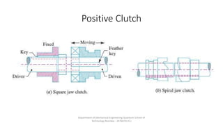
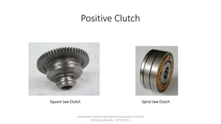
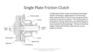
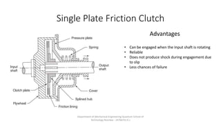
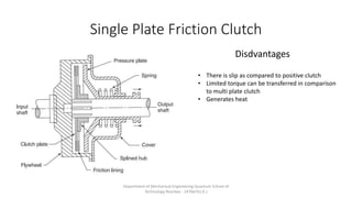
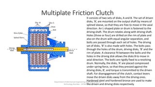
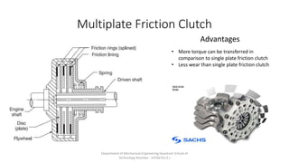
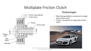
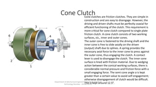
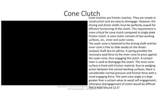
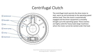
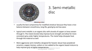
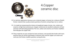
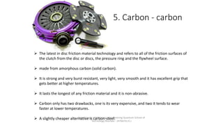
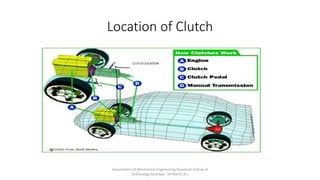
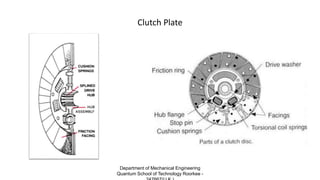
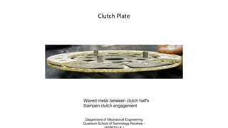
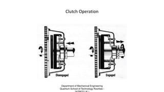
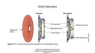
Automotive Clutch
Submitted by
Khusro Kamaluddin
ME-1 IIIrd Year Roll No 39
Submitted to
Mr. Ashish Bist
Mr. Ashutosh Sharma
Department of Mechanical Engineering Quantum School of
Technology Roorkee - 247667(U.K.)
Clutch
A Clutch is a mechanical device which is used to connect or disconnect
the source of power from the remaining parts so the power
transmission system at the will of the operator. The flow of mechanical
power is controlled by the clutch.
Department of Mechanical Engineering Quantum School of
Technology Roorkee - 247667(U.K.)
Types of Clutches
• 1 Positive Clutch
• 2 Friction Clutch
Department of Mechanical Engineering Quantum School of
Technology Roorkee - 247667(U.K.)
Positive Clutch
Positive Clutches: In this type of clutch, the engaging clutch surfaces
interlock to produce rigid joint they are suitable for situations requiring
simple and rapid disconnection, although they must be connected while
shafts are stationery and unloaded, the engaging surfaces are usually of
jaw type. The jaws may be square jaw type or spiral jaw type. They are
designed empirically by considering compressive strength of the
material used.
Department of Mechanical Engineering Quantum School of
Technology Roorkee - 247667(U.K.)
Positive Clutch
Department of Mechanical Engineering Quantum School of
Technology Roorkee - 247667(U.K.)
Positive Clutch
Square Jaw Clutch Spiral Jaw Clutch
Department of Mechanical Engineering Quantum School of
Technology Roorkee - 247667(U.K.)
Positive Clutch
Department of Mechanical Engineering Quantum School of
Technology Roorkee - 247667(U.K.)
Positive Clutch
Advantages
• Simple
• No Slip
• No heat generated
• Compact
• Low cost
Disadvantages
• Must be connected when shaft is
unloaded
Department of Mechanical Engineering Quantum School of
Technology Roorkee - 247667(U.K.)
Friction Clutch
• Friction Clutches work on the basis of the frictional forces developed
between the two or more surfaces in contact. Friction clutches are
usually – over the jaw clutches due to their better performance.
There is a slip in friction clutch
Department of Mechanical Engineering Quantum School of
Technology Roorkee - 247667(U.K.)
Friction Clutch
The major types of friction clutches are
• Single Plate Clutch
• Multi Plate clutch
• Cone clutch
• Centrifugal clutch
Department of Mechanical Engineering Quantum School of
Technology Roorkee - 247667(U.K.)
Single Plate Friction Clutch
A single plate friction clutch consisting of two flanges
shown. One flange is rigidly keyed in to the driving
shaft, while the other is free to move along the driven
shaft due to spliced connection. The actuating force is
provided by a spring, which forces the driven flange to
move towards the driving flange. The face of the drive
flange is linked with friction material such as cork,
leather or ferodo
Department of Mechanical Engineering Quantum School of
Technology Roorkee - 247667(U.K.)
Single Plate Friction Clutch
Advantages
• Can be engaged when the Input shaft is rotating
• Reliable
• Does not produce shock during engagement due
to slip
• Less chances of failure
Department of Mechanical Engineering Quantum School of
Technology Roorkee - 247667(U.K.)
Single Plate Friction Clutch
Disdvantages
• There is slip as compared to positive clutch
• Limited torque can be transferred in comparison
to multi plate clutch
• Generates heat
Department of Mechanical Engineering Quantum School of
Technology Roorkee - 247667(U.K.)
Single Plate Friction Clutch
Department of Mechanical Engineering Quantum School of
Technology Roorkee - 247667(U.K.)
Multiplate Friction Clutch
It consists of two sets of disks, A and B. The set of driven
disks, ‘A’, are mounted on the output shaft by means of
splined sleeve, so that they are free to move in the axial
direction. An L-shaped plate or drum is fastened to the
driving shaft. The drum rotates along with driving shaft.
Holes (three or four) are drilled on the rim of plate and
also on the drum with equal angular separation, and
bolts are passed through each set of holes. The driving
set of disks, ‘B’ is also made with holes. The bolts pass
through the holes of the drum, driving disks, ‘B’ and the
rim of plate. A clearance fit between the bolts and the
holes in the driving disk allows the disks B to move in
axial direction. The bolts are rigidly fixed to a revolving
drum. Normally, the disks, ‘A’ are placed compressed
under spring force, so that they pressed against the
driving disks, B’, and torque is transmitted to the driven
shaft. For disengagement of the clutch, contact levers
move the driven disks away from the driving ones.
Hardened steel and hardened bronze are used to make
the driven and driving disks respectively.
Department of Mechanical Engineering Quantum School of
Technology Roorkee - 247667(U.K.)
Multiplate Friction Clutch
Advantages
• More torque can be transferred in
comparison to single plate friction clutch
• Less wear than single plate friction clutch
Department of Mechanical Engineering Quantum School of
Technology Roorkee - 247667(U.K.)
Multiplate Friction Clutch
Disdvantages
• More heat genetated in comparison to single
plate friction clutch
• Costly in comparison to single plate friction
clutch
Department of Mechanical Engineering Quantum School of
Technology Roorkee - 247667(U.K.)
Cone ClutchCone clutches are friction clutches. They are simple in
construction and are easy to disengage. However, the
driving and driven shafts must be perfectly coaxial for
efficient functioning of the clutch. This requirement is
more critical for cone clutch compared to single plate
friction clutch. A cone clutch consists of two working
surfaces, viz., inner and outer cones.
The outer cone is fastened to the driving shaft and the
inner cone is free to slide axially on the driven
(output) shaft due to splines. A spring provides the
necessary axial force to the inner cone to press against
the outer cone, thus engaging the clutch. A contact
lever is used to disengage the clutch. The inner cone
surface is lined with friction material. Due to wedging
action between the conical working surfaces, there is
considerable normal pressure and friction force with a
small engaging force. The semi cone angle a is kept
greater than a certain value to avoid self-engagement;
otherwise disengagement of clutch would be difficult.
This is kept around 12.50.Department of Mechanical Engineering Quantum School of
Technology Roorkee - 247667(U.K.)
Centrifugal Clutch
The centrifugal clutch permits the drive motor to
start, warm up and accelerate to the operating speed
without load. Then the clutch is automatically
engaged and the driven equipment is smoothly
brought up to the operating speed. These clutches
are highly useful for heavy loads (large machines)
where the motor cannot be started under that load.
Department of Mechanical Engineering Quantum School of
Technology Roorkee - 247667(U.K.)
Centrifugal Clutch
Centrifugal clutch is widely used in textile machinery
such as looms, carding-, knitting-, drawing-, roving-
and spinning machines.
For example, a centrifugal clutch is used in the drive
from motor to cylinder and lickerin on a high speed
card. Once the motor attains the required speed,
the centrifugal clutch engages, transmitting the
drive to lickerin and cylinder, thus safe guarding the
motor during start-up. Centrifugal clutch is
economical and requires less maintenance to any
other motor safety device such coupling.
Application
Department of Mechanical Engineering Quantum School of
Technology Roorkee - 247667(U.K.)
Materials for Friction lining
• Asbestos-based materials and sintered metals are commonly used for
friction lining. There are two types of asbestos friction disks: woven and
moulded. A woven asbestos friction disk consists of asbestos fibre woven
with endless circular weave around brass, copper or zinc wires and then
impregnated with rubber or asphalt. The endless circular weave increases
the bursting strength. Moulded asbestos friction disks are prepared by
moulding the wet mixture of brass chips and asbestos. The woven
materials are flexible, have higher coefficient of friction, conform more
readily to clutch surface, costly and wear at faster rate compared to
moulded materials. Asbestos materials are less heat resistant even at low
temperature. Sintered-metal friction materials have higher wear resistance,
high temperature-resistant, constant coefficient of friction over a wide
range of temperature and pressure, and are unaffected by environmental
conditions. They also offer lighter, cheaper and compact construction of
friction clutches.
Department of Mechanical Engineering Quantum School of
Technology Roorkee - 247667(U.K.)
1. Organic disc
material  Organic friction material is made of
cellulose, usually reinforced with some
heat resistant stuff like chopped
fiberglass and mineral wool in a
thermosetting phenolic resin base.
 The cellulose is like cardboard and
helps initial grip.
 The mineral wool and fiberglass strands
provide burst strength, which is the
friction material’s resistance to
breaking up and falling apart, especially
with shear and centrifugal load.
Department of Mechanical Engineering Quantum School of
Technology Roorkee - 247667(U.K.)
2. Heavy duty
(HD)
 Heavy Duty (HD) and racing discs have friction material made of several different
ingredients.
 A mild HD disc usually uses chopped Kevlar strands in a phenolic resin base. Kevlar is
a space-age aramid fiber that is six times stronger than steel in tension and is fairly
heat resistant.
 Kevlar offers good burst strength and good wearing characteristics but has relatively
poor frictional gripping properties. This makes for smooth engagement
characteristics but only average grip.Department of Mechanical Engineering Quantum School of
Technology Roorkee - 247667(U.K.)
3. Semi-metallic
disc
• usually the best compromise for modified streetcar because they have a nice
balance between smoothness, long life, good grip and low wear.
• typical semi-metallic is an organic disc with strands of copper or brass woven
through it. The metal strands help improve burst strength and allow for more
consistent grip under higher temperatures. The metal helps dissipate heat
through the material as well.
• More aggressive semi-metallics designed for heavier abuse have powdered
ceramics, copper, bronze, carbon or iron added to the organic based mixture to
help improve grip at higher temperatures.Department of Mechanical Engineering Quantum School of
Technology Roorkee - 247667(U.K.)
4.Copper
ceramic disc
 For extreme applications because use a sintered copper or bronze (or a mixture of both)
friction material that usually contains particles of ceramic and perhaps iron or carbon.
 It is made by compressing the mixture of powdered copper, bronze, iron, carbon and
ceramics at high heat and pressure. Copper and bronze are excellent conductors of heat
and have self-lubricating properties The iron, carbon and ceramics are friction modifiers
that help give the copper bite.
 These materials are very resistant to heat and abuse, and actually bite harder with more
heat but they can still be overheated in extreme cases and the copper can smear and
melt over the friction modifier particles ruining the disc.
Department of Mechanical Engineering Quantum School of
Technology Roorkee - 247667(U.K.)
5. Carbon - carbon
 The latest in disc friction material technology and refers to all of the friction surfaces of
the clutch from the disc or discs, the pressure ring and the flywheel surface.
 made from amorphous carbon (solid carbon).
 It is strong and very burst resistant, very light, very smooth and it has excellent grip that
gets better at higher temperatures.
 It lasts the longest of any friction material and it is non-abrasive.
 Carbon only has two drawbacks, one is its very expensive, and two it tends to wear
faster at lower temperatures.
 A slightly cheaper alternative is carbon-steel.Department of Mechanical Engineering Quantum School of
Technology Roorkee - 247667(U.K.)
Location of Clutch
Department of Mechanical Engineering Quantum School of
Technology Roorkee - 247667(U.K.)
Location of Clutch
Department of Mechanical Engineering Quantum School of
Technology Roorkee - 247667(U.K.)
Location of Clutch
Department of Mechanical Engineering Quantum School of
Technology Roorkee - 247667(U.K.)
Clutch Assembly
Department of Mechanical Engineering
Quantum School of Technology Roorkee -
Clutch Assembly
Flywheel GearboxClutch plate Assemly
and release Bearing
Department of Mechanical Engineering
Quantum School of Technology Roorkee -
Clutch Assembly
Department of Mechanical Engineering
Quantum School of Technology Roorkee -
Clutch Plate
Department of Mechanical Engineering
Quantum School of Technology Roorkee -
Clutch Plate
Waved metal between clutch half's
Dampen clutch engagement
Department of Mechanical Engineering
Quantum School of Technology Roorkee -
Clutch Operation
Department of Mechanical Engineering
Quantum School of Technology Roorkee -
Clutch Operation
Department of Mechanical Engineering
Quantum School of Technology Roorkee -
Clutch Operation
Bolted to Crank
(friction disk) splined to transmission
Input shaft
(throw-out bearing
T/O bearing) allows
to push on rotating
clutch fingers
Bolted to flywheel - Applies
the spring force to clamp the
friction disk to the flywheel (clutch fork) pushes
T/O bearing to release
rotating clutch
Pilot bushing or bearing in center
of flywheel or crankshaft, supports
the end of input shaft
Department of Mechanical Engineering
Quantum School of Technology Roorkee -
Clutch Operation
Department of Mechanical Engineering
Quantum School of Technology Roorkee -
Clutch Control
The disengagement of the clutch is caused primarily
by the force acted on the diaphragm by the
movement of the release bearing . This movement is
transferred to the release bearing via a fork which
acts as a lever usually pivoted on one(or 2) ball pivot
in the cover of the gearbox.
The following clutch release mechanisms :
1. Mechanical or linkage mechanism
2. Cable Mechanism
3. Hydraulic Mechanism
Department of Mechanical Engineering
Quantum School of Technology Roorkee -
Release fork
Rotating Type Lever Type
Department of Mechanical Engineering
Quantum School of Technology Roorkee -
Ball Pivot
Ball Pivot
Ball Pivot
Department of Mechanical Engineering
Quantum School of Technology Roorkee -
Clutch Boot
Clutch Boot is used to prevent dust and dirt to enter the housing
Department of Mechanical Engineering
Quantum School of Technology Roorkee -
Mechanical or linkage Mechanism
• consists of a bellcrank that pivots
between the frame and the engine
block. One side of the bell crank
attaches to the clutch pedal, and the
opposite side attaches to the
adjustment rod for clutch release.
• The adjustment rod is inserted into
the clutch fork and lengthened or
shortened to achieve the proper
release and gap between the clutch
fingers and the bearing.
• the ratio between the release
mechanism and the pedal effort is
between three and four to
one. Mechanical linkages provide
the most flexibility in clutch
adjustment.Department of Mechanical Engineering
Quantum School of Technology Roorkee -
Cable Mechanism
• A cable linkage can perform the same
controlling action as the mechanical clutch but
with fewer parts.
• The clutch cable system does not take up much
room.
• It also has the advantage of flexible installation
so it can be routed around the power brake
and steering units.
• These advantages help to make it the most
commonly used clutch linkage.
Department of Mechanical Engineering
Quantum School of Technology Roorkee -
Hydraulic Mechanism
• In the hydraulic clutch linkage system,
hydraulic pressure transmits motion from one
sealed cylinder to another through a hydraulic
line.
• Like the cable linkage assembly, the hydraulic
linkage is compact and flexible.
• Hydraulic linkages allow the placement of the
release fork anywhere that gives which gives
more flexibility in body design
Department of Mechanical Engineering
Quantum School of Technology Roorkee -
Hydraulic Mechanism
Master Cylinder Slave Cylinder
Department of Mechanical Engineering
Quantum School of Technology Roorkee -
Clutch Replacement
A clutch replacement is a consequence of the following :
• Clutch slips while engaged
• Clutch chatters while engaging
• Clutch spins while disengaging
• Clutch noisy while engaged
• Clutch noisy while disengaging
• Clutch pedal pulsates
• Clutch pedal is stiff
Department of Mechanical Engineering
Quantum School of Technology Roorkee -
Clutch Replacement Procedure
Department of Mechanical Engineering
Quantum School of Technology Roorkee -
Clutch Replacement Procedure
Removal of the drive
shaft
Opening the two
U-Joints
Department of Mechanical Engineering
Quantum School of Technology Roorkee -
Clutch Replacement Procedure
Department of Mechanical Engineering
Quantum School of Technology Roorkee -
Clutch Replacement Procedure
Department of Mechanical Engineering
Quantum School of Technology Roorkee -
Clutch Replacement Procedure
Department of Mechanical Engineering
Quantum School of Technology Roorkee -
Clutch Replacement Procedure
Department of Mechanical Engineering
Quantum School of Technology Roorkee -
Clutch Replacement Procedure
Department of Mechanical Engineering
Quantum School of Technology Roorkee -
Clutch Replacement Procedure
Department of Mechanical Engineering
Quantum School of Technology Roorkee -
Clutch Replacement Procedure
Department of Mechanical Engineering
Quantum School of Technology Roorkee -
Clutch Replacement Procedure
Department of Mechanical Engineering
Quantum School of Technology Roorkee -
Clutch Replacement Procedure
Checking pressure plate for warpage using
feeler gauge.
Department of Mechanical Engineering
Quantum School of Technology Roorkee -
Clutch Replacement Procedure
Pilot Shaft
Universal Clutch Alignment Tool
Department of Mechanical Engineering
Quantum School of Technology Roorkee -
Thank You
Department of Mechanical Engineering
Quantum School of Technology Roorkee -
Bilblography
• Automotive Mechanics, William H. Crouse 10E Tata
McGraw Hill Pvt. Ltd.
• NPTEL, Machine Design II, Prof. K.Gopinath & Prof.
M.M.Mayuram
• NPTEL, Mechanics of Textile Machinery
• How Stuff Works, Clutch
Department of Mechanical Engineering
Quantum School of Technology Roorkee -

Automotive clutch

  • 1.
    Automotive Clutch Submitted by KhusroKamaluddin ME-1 IIIrd Year Roll No 39 Submitted to Mr. Ashish Bist Mr. Ashutosh Sharma Department of Mechanical Engineering Quantum School of Technology Roorkee - 247667(U.K.)
  • 2.
    Clutch A Clutch isa mechanical device which is used to connect or disconnect the source of power from the remaining parts so the power transmission system at the will of the operator. The flow of mechanical power is controlled by the clutch. Department of Mechanical Engineering Quantum School of Technology Roorkee - 247667(U.K.)
  • 3.
    Types of Clutches •1 Positive Clutch • 2 Friction Clutch Department of Mechanical Engineering Quantum School of Technology Roorkee - 247667(U.K.)
  • 4.
    Positive Clutch Positive Clutches:In this type of clutch, the engaging clutch surfaces interlock to produce rigid joint they are suitable for situations requiring simple and rapid disconnection, although they must be connected while shafts are stationery and unloaded, the engaging surfaces are usually of jaw type. The jaws may be square jaw type or spiral jaw type. They are designed empirically by considering compressive strength of the material used. Department of Mechanical Engineering Quantum School of Technology Roorkee - 247667(U.K.)
  • 5.
    Positive Clutch Department ofMechanical Engineering Quantum School of Technology Roorkee - 247667(U.K.)
  • 6.
    Positive Clutch Square JawClutch Spiral Jaw Clutch Department of Mechanical Engineering Quantum School of Technology Roorkee - 247667(U.K.)
  • 7.
    Positive Clutch Department ofMechanical Engineering Quantum School of Technology Roorkee - 247667(U.K.)
  • 8.
    Positive Clutch Advantages • Simple •No Slip • No heat generated • Compact • Low cost Disadvantages • Must be connected when shaft is unloaded Department of Mechanical Engineering Quantum School of Technology Roorkee - 247667(U.K.)
  • 9.
    Friction Clutch • FrictionClutches work on the basis of the frictional forces developed between the two or more surfaces in contact. Friction clutches are usually – over the jaw clutches due to their better performance. There is a slip in friction clutch Department of Mechanical Engineering Quantum School of Technology Roorkee - 247667(U.K.)
  • 10.
    Friction Clutch The majortypes of friction clutches are • Single Plate Clutch • Multi Plate clutch • Cone clutch • Centrifugal clutch Department of Mechanical Engineering Quantum School of Technology Roorkee - 247667(U.K.)
  • 11.
    Single Plate FrictionClutch A single plate friction clutch consisting of two flanges shown. One flange is rigidly keyed in to the driving shaft, while the other is free to move along the driven shaft due to spliced connection. The actuating force is provided by a spring, which forces the driven flange to move towards the driving flange. The face of the drive flange is linked with friction material such as cork, leather or ferodo Department of Mechanical Engineering Quantum School of Technology Roorkee - 247667(U.K.)
  • 12.
    Single Plate FrictionClutch Advantages • Can be engaged when the Input shaft is rotating • Reliable • Does not produce shock during engagement due to slip • Less chances of failure Department of Mechanical Engineering Quantum School of Technology Roorkee - 247667(U.K.)
  • 13.
    Single Plate FrictionClutch Disdvantages • There is slip as compared to positive clutch • Limited torque can be transferred in comparison to multi plate clutch • Generates heat Department of Mechanical Engineering Quantum School of Technology Roorkee - 247667(U.K.)
  • 14.
    Single Plate FrictionClutch Department of Mechanical Engineering Quantum School of Technology Roorkee - 247667(U.K.)
  • 15.
    Multiplate Friction Clutch Itconsists of two sets of disks, A and B. The set of driven disks, ‘A’, are mounted on the output shaft by means of splined sleeve, so that they are free to move in the axial direction. An L-shaped plate or drum is fastened to the driving shaft. The drum rotates along with driving shaft. Holes (three or four) are drilled on the rim of plate and also on the drum with equal angular separation, and bolts are passed through each set of holes. The driving set of disks, ‘B’ is also made with holes. The bolts pass through the holes of the drum, driving disks, ‘B’ and the rim of plate. A clearance fit between the bolts and the holes in the driving disk allows the disks B to move in axial direction. The bolts are rigidly fixed to a revolving drum. Normally, the disks, ‘A’ are placed compressed under spring force, so that they pressed against the driving disks, B’, and torque is transmitted to the driven shaft. For disengagement of the clutch, contact levers move the driven disks away from the driving ones. Hardened steel and hardened bronze are used to make the driven and driving disks respectively. Department of Mechanical Engineering Quantum School of Technology Roorkee - 247667(U.K.)
  • 16.
    Multiplate Friction Clutch Advantages •More torque can be transferred in comparison to single plate friction clutch • Less wear than single plate friction clutch Department of Mechanical Engineering Quantum School of Technology Roorkee - 247667(U.K.)
  • 17.
    Multiplate Friction Clutch Disdvantages •More heat genetated in comparison to single plate friction clutch • Costly in comparison to single plate friction clutch Department of Mechanical Engineering Quantum School of Technology Roorkee - 247667(U.K.)
  • 18.
    Cone ClutchCone clutchesare friction clutches. They are simple in construction and are easy to disengage. However, the driving and driven shafts must be perfectly coaxial for efficient functioning of the clutch. This requirement is more critical for cone clutch compared to single plate friction clutch. A cone clutch consists of two working surfaces, viz., inner and outer cones. The outer cone is fastened to the driving shaft and the inner cone is free to slide axially on the driven (output) shaft due to splines. A spring provides the necessary axial force to the inner cone to press against the outer cone, thus engaging the clutch. A contact lever is used to disengage the clutch. The inner cone surface is lined with friction material. Due to wedging action between the conical working surfaces, there is considerable normal pressure and friction force with a small engaging force. The semi cone angle a is kept greater than a certain value to avoid self-engagement; otherwise disengagement of clutch would be difficult. This is kept around 12.50.Department of Mechanical Engineering Quantum School of Technology Roorkee - 247667(U.K.)
  • 19.
    Cone ClutchCone clutchesare friction clutches. They are simple in construction and are easy to disengage. However, the driving and driven shafts must be perfectly coaxial for efficient functioning of the clutch. This requirement is more critical for cone clutch compared to single plate friction clutch. A cone clutch consists of two working surfaces, viz., inner and outer cones. The outer cone is fastened to the driving shaft and the inner cone is free to slide axially on the driven (output) shaft due to splines. A spring provides the necessary axial force to the inner cone to press against the outer cone, thus engaging the clutch. A contact lever is used to disengage the clutch. The inner cone surface is lined with friction material. Due to wedging action between the conical working surfaces, there is considerable normal pressure and friction force with a small engaging force. The semi cone angle a is kept greater than a certain value to avoid self-engagement; otherwise disengagement of clutch would be difficult. This is kept around 12.50.Department of Mechanical Engineering Quantum School of Technology Roorkee - 247667(U.K.)
  • 20.
    Centrifugal Clutch The centrifugalclutch permits the drive motor to start, warm up and accelerate to the operating speed without load. Then the clutch is automatically engaged and the driven equipment is smoothly brought up to the operating speed. These clutches are highly useful for heavy loads (large machines) where the motor cannot be started under that load. Department of Mechanical Engineering Quantum School of Technology Roorkee - 247667(U.K.)
  • 21.
    Centrifugal Clutch Centrifugal clutchis widely used in textile machinery such as looms, carding-, knitting-, drawing-, roving- and spinning machines. For example, a centrifugal clutch is used in the drive from motor to cylinder and lickerin on a high speed card. Once the motor attains the required speed, the centrifugal clutch engages, transmitting the drive to lickerin and cylinder, thus safe guarding the motor during start-up. Centrifugal clutch is economical and requires less maintenance to any other motor safety device such coupling. Application Department of Mechanical Engineering Quantum School of Technology Roorkee - 247667(U.K.)
  • 22.
    Materials for Frictionlining • Asbestos-based materials and sintered metals are commonly used for friction lining. There are two types of asbestos friction disks: woven and moulded. A woven asbestos friction disk consists of asbestos fibre woven with endless circular weave around brass, copper or zinc wires and then impregnated with rubber or asphalt. The endless circular weave increases the bursting strength. Moulded asbestos friction disks are prepared by moulding the wet mixture of brass chips and asbestos. The woven materials are flexible, have higher coefficient of friction, conform more readily to clutch surface, costly and wear at faster rate compared to moulded materials. Asbestos materials are less heat resistant even at low temperature. Sintered-metal friction materials have higher wear resistance, high temperature-resistant, constant coefficient of friction over a wide range of temperature and pressure, and are unaffected by environmental conditions. They also offer lighter, cheaper and compact construction of friction clutches. Department of Mechanical Engineering Quantum School of Technology Roorkee - 247667(U.K.)
  • 23.
    1. Organic disc material Organic friction material is made of cellulose, usually reinforced with some heat resistant stuff like chopped fiberglass and mineral wool in a thermosetting phenolic resin base.  The cellulose is like cardboard and helps initial grip.  The mineral wool and fiberglass strands provide burst strength, which is the friction material’s resistance to breaking up and falling apart, especially with shear and centrifugal load. Department of Mechanical Engineering Quantum School of Technology Roorkee - 247667(U.K.)
  • 24.
    2. Heavy duty (HD) Heavy Duty (HD) and racing discs have friction material made of several different ingredients.  A mild HD disc usually uses chopped Kevlar strands in a phenolic resin base. Kevlar is a space-age aramid fiber that is six times stronger than steel in tension and is fairly heat resistant.  Kevlar offers good burst strength and good wearing characteristics but has relatively poor frictional gripping properties. This makes for smooth engagement characteristics but only average grip.Department of Mechanical Engineering Quantum School of Technology Roorkee - 247667(U.K.)
  • 25.
    3. Semi-metallic disc • usuallythe best compromise for modified streetcar because they have a nice balance between smoothness, long life, good grip and low wear. • typical semi-metallic is an organic disc with strands of copper or brass woven through it. The metal strands help improve burst strength and allow for more consistent grip under higher temperatures. The metal helps dissipate heat through the material as well. • More aggressive semi-metallics designed for heavier abuse have powdered ceramics, copper, bronze, carbon or iron added to the organic based mixture to help improve grip at higher temperatures.Department of Mechanical Engineering Quantum School of Technology Roorkee - 247667(U.K.)
  • 26.
    4.Copper ceramic disc  Forextreme applications because use a sintered copper or bronze (or a mixture of both) friction material that usually contains particles of ceramic and perhaps iron or carbon.  It is made by compressing the mixture of powdered copper, bronze, iron, carbon and ceramics at high heat and pressure. Copper and bronze are excellent conductors of heat and have self-lubricating properties The iron, carbon and ceramics are friction modifiers that help give the copper bite.  These materials are very resistant to heat and abuse, and actually bite harder with more heat but they can still be overheated in extreme cases and the copper can smear and melt over the friction modifier particles ruining the disc. Department of Mechanical Engineering Quantum School of Technology Roorkee - 247667(U.K.)
  • 27.
    5. Carbon -carbon  The latest in disc friction material technology and refers to all of the friction surfaces of the clutch from the disc or discs, the pressure ring and the flywheel surface.  made from amorphous carbon (solid carbon).  It is strong and very burst resistant, very light, very smooth and it has excellent grip that gets better at higher temperatures.  It lasts the longest of any friction material and it is non-abrasive.  Carbon only has two drawbacks, one is its very expensive, and two it tends to wear faster at lower temperatures.  A slightly cheaper alternative is carbon-steel.Department of Mechanical Engineering Quantum School of Technology Roorkee - 247667(U.K.)
  • 28.
    Location of Clutch Departmentof Mechanical Engineering Quantum School of Technology Roorkee - 247667(U.K.)
  • 29.
    Location of Clutch Departmentof Mechanical Engineering Quantum School of Technology Roorkee - 247667(U.K.)
  • 30.
    Location of Clutch Departmentof Mechanical Engineering Quantum School of Technology Roorkee - 247667(U.K.)
  • 31.
    Clutch Assembly Department ofMechanical Engineering Quantum School of Technology Roorkee -
  • 32.
    Clutch Assembly Flywheel GearboxClutchplate Assemly and release Bearing Department of Mechanical Engineering Quantum School of Technology Roorkee -
  • 33.
    Clutch Assembly Department ofMechanical Engineering Quantum School of Technology Roorkee -
  • 34.
    Clutch Plate Department ofMechanical Engineering Quantum School of Technology Roorkee -
  • 35.
    Clutch Plate Waved metalbetween clutch half's Dampen clutch engagement Department of Mechanical Engineering Quantum School of Technology Roorkee -
  • 36.
    Clutch Operation Department ofMechanical Engineering Quantum School of Technology Roorkee -
  • 37.
    Clutch Operation Department ofMechanical Engineering Quantum School of Technology Roorkee -
  • 38.
    Clutch Operation Bolted toCrank (friction disk) splined to transmission Input shaft (throw-out bearing T/O bearing) allows to push on rotating clutch fingers Bolted to flywheel - Applies the spring force to clamp the friction disk to the flywheel (clutch fork) pushes T/O bearing to release rotating clutch Pilot bushing or bearing in center of flywheel or crankshaft, supports the end of input shaft Department of Mechanical Engineering Quantum School of Technology Roorkee -
  • 39.
    Clutch Operation Department ofMechanical Engineering Quantum School of Technology Roorkee -
  • 40.
    Clutch Control The disengagementof the clutch is caused primarily by the force acted on the diaphragm by the movement of the release bearing . This movement is transferred to the release bearing via a fork which acts as a lever usually pivoted on one(or 2) ball pivot in the cover of the gearbox. The following clutch release mechanisms : 1. Mechanical or linkage mechanism 2. Cable Mechanism 3. Hydraulic Mechanism Department of Mechanical Engineering Quantum School of Technology Roorkee -
  • 41.
    Release fork Rotating TypeLever Type Department of Mechanical Engineering Quantum School of Technology Roorkee -
  • 42.
    Ball Pivot Ball Pivot BallPivot Department of Mechanical Engineering Quantum School of Technology Roorkee -
  • 43.
    Clutch Boot Clutch Bootis used to prevent dust and dirt to enter the housing Department of Mechanical Engineering Quantum School of Technology Roorkee -
  • 44.
    Mechanical or linkageMechanism • consists of a bellcrank that pivots between the frame and the engine block. One side of the bell crank attaches to the clutch pedal, and the opposite side attaches to the adjustment rod for clutch release. • The adjustment rod is inserted into the clutch fork and lengthened or shortened to achieve the proper release and gap between the clutch fingers and the bearing. • the ratio between the release mechanism and the pedal effort is between three and four to one. Mechanical linkages provide the most flexibility in clutch adjustment.Department of Mechanical Engineering Quantum School of Technology Roorkee -
  • 45.
    Cable Mechanism • Acable linkage can perform the same controlling action as the mechanical clutch but with fewer parts. • The clutch cable system does not take up much room. • It also has the advantage of flexible installation so it can be routed around the power brake and steering units. • These advantages help to make it the most commonly used clutch linkage. Department of Mechanical Engineering Quantum School of Technology Roorkee -
  • 46.
    Hydraulic Mechanism • Inthe hydraulic clutch linkage system, hydraulic pressure transmits motion from one sealed cylinder to another through a hydraulic line. • Like the cable linkage assembly, the hydraulic linkage is compact and flexible. • Hydraulic linkages allow the placement of the release fork anywhere that gives which gives more flexibility in body design Department of Mechanical Engineering Quantum School of Technology Roorkee -
  • 47.
    Hydraulic Mechanism Master CylinderSlave Cylinder Department of Mechanical Engineering Quantum School of Technology Roorkee -
  • 48.
    Clutch Replacement A clutchreplacement is a consequence of the following : • Clutch slips while engaged • Clutch chatters while engaging • Clutch spins while disengaging • Clutch noisy while engaged • Clutch noisy while disengaging • Clutch pedal pulsates • Clutch pedal is stiff Department of Mechanical Engineering Quantum School of Technology Roorkee -
  • 49.
    Clutch Replacement Procedure Departmentof Mechanical Engineering Quantum School of Technology Roorkee -
  • 50.
    Clutch Replacement Procedure Removalof the drive shaft Opening the two U-Joints Department of Mechanical Engineering Quantum School of Technology Roorkee -
  • 51.
    Clutch Replacement Procedure Departmentof Mechanical Engineering Quantum School of Technology Roorkee -
  • 52.
    Clutch Replacement Procedure Departmentof Mechanical Engineering Quantum School of Technology Roorkee -
  • 53.
    Clutch Replacement Procedure Departmentof Mechanical Engineering Quantum School of Technology Roorkee -
  • 54.
    Clutch Replacement Procedure Departmentof Mechanical Engineering Quantum School of Technology Roorkee -
  • 55.
    Clutch Replacement Procedure Departmentof Mechanical Engineering Quantum School of Technology Roorkee -
  • 56.
    Clutch Replacement Procedure Departmentof Mechanical Engineering Quantum School of Technology Roorkee -
  • 57.
    Clutch Replacement Procedure Departmentof Mechanical Engineering Quantum School of Technology Roorkee -
  • 58.
    Clutch Replacement Procedure Departmentof Mechanical Engineering Quantum School of Technology Roorkee -
  • 59.
    Clutch Replacement Procedure Checkingpressure plate for warpage using feeler gauge. Department of Mechanical Engineering Quantum School of Technology Roorkee -
  • 60.
    Clutch Replacement Procedure PilotShaft Universal Clutch Alignment Tool Department of Mechanical Engineering Quantum School of Technology Roorkee -
  • 61.
    Thank You Department ofMechanical Engineering Quantum School of Technology Roorkee -
  • 62.
    Bilblography • Automotive Mechanics,William H. Crouse 10E Tata McGraw Hill Pvt. Ltd. • NPTEL, Machine Design II, Prof. K.Gopinath & Prof. M.M.Mayuram • NPTEL, Mechanics of Textile Machinery • How Stuff Works, Clutch Department of Mechanical Engineering Quantum School of Technology Roorkee -