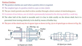
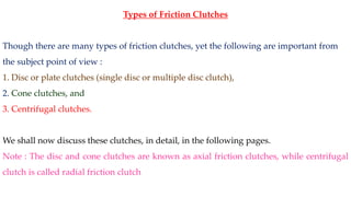
1. The document discusses clutches and provides details on different types of clutches including positive clutches and friction clutches.
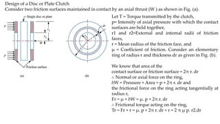
2. It describes the single disc or plate clutch and provides details on its components and working. Factors considered in designing disc clutches including uniform pressure distribution and uniform axial wear are also summarized.
3. Various materials used for friction surfaces in clutches are listed along with their important properties for withstanding heat and friction.