Downloaded 20 times

![IJRET: International Journal of Research in Engineering and Technology eISSN: 2319-1163 | pISSN: 2321-7308
_______________________________________________________________________________________
Volume: 04 Issue: 04 | Apr-2015, Available @ http://www.ijret.org 175
6. CONCLUSION
We established a system Automation in Agriculture Field
Using ARM 7 Based Robot to overcome the problematic
issues of farming. Like water resource management,
accurate watering according to requirement of plant.
Movable water sprinkler to reduce the cost and human
efforts. By using an advance system and components
developed and elite and well manner algorithm for
execution. Shown all research done the, all simulation and
graphs.
REFERENCES
[1] Wark.T, Corke.p,etal,”Transforming Agriculture
through pervasive Wireless Sensor Networks.”
Pervasive computing , IEEE, 2007,6(2):pp.50-57.
[2] Stephen J. Katzberg, Omar Torres, Michael S. Grant,
Dallas Masters.“Utilizing calibrated GPS reflected
signals to estimate soil reflectivity and dielectric
constant: Results from SMEX02.” Remote Sensing
of Environment,2005 (100): 17-28.
[3] Caparrini,M, Egido.A; Soulat. F, Germain.O;
Farres.E, Dunne.S, Ruffini. G, “Oceanpal®:
Monitoring sea state with a GNSS-R coastal
instrumen”. Geoscience and Remote Sensing
Symposium, 2007.IGARSS 2007. IEEE International,
2007 Page(s):5080 – 5083
[4] 100 Electronics projects-Bright publications.
[5] BASIC for AVR microcontrollers by -Nebojsa Matic
[6] Code Vision tutorials -Saurabh Sankule(I.I.T.
Kanpur)
[7] Bull,S.R., renewable energy sources and Rural
Development in Developing Countries”, Proceedings
of the IEEE 2001
BIOGRAPHIES
Praveen Kumar Singh, He is pursuing his
degree in Pimpri Chinchwad College of
Engineering, Pune
Gaurav.S. Nikam, He is pursuing his
degree in Pimpri Chinchwad College of
Engineering, Pune
Mrs.Rupali.S.Kad, she’s a Assistant
Professor in Pimpri Chinchwad College
Of Engineering, Pune. Her area of
interest is Process Automation and
Electronic instrumentation.](https://image.slidesharecdn.com/automationinagriculturefieldusingarm7basedrobot-160903052456/85/Automation-in-agriculture-field-using-arm-7-based-robot-5-320.jpg)

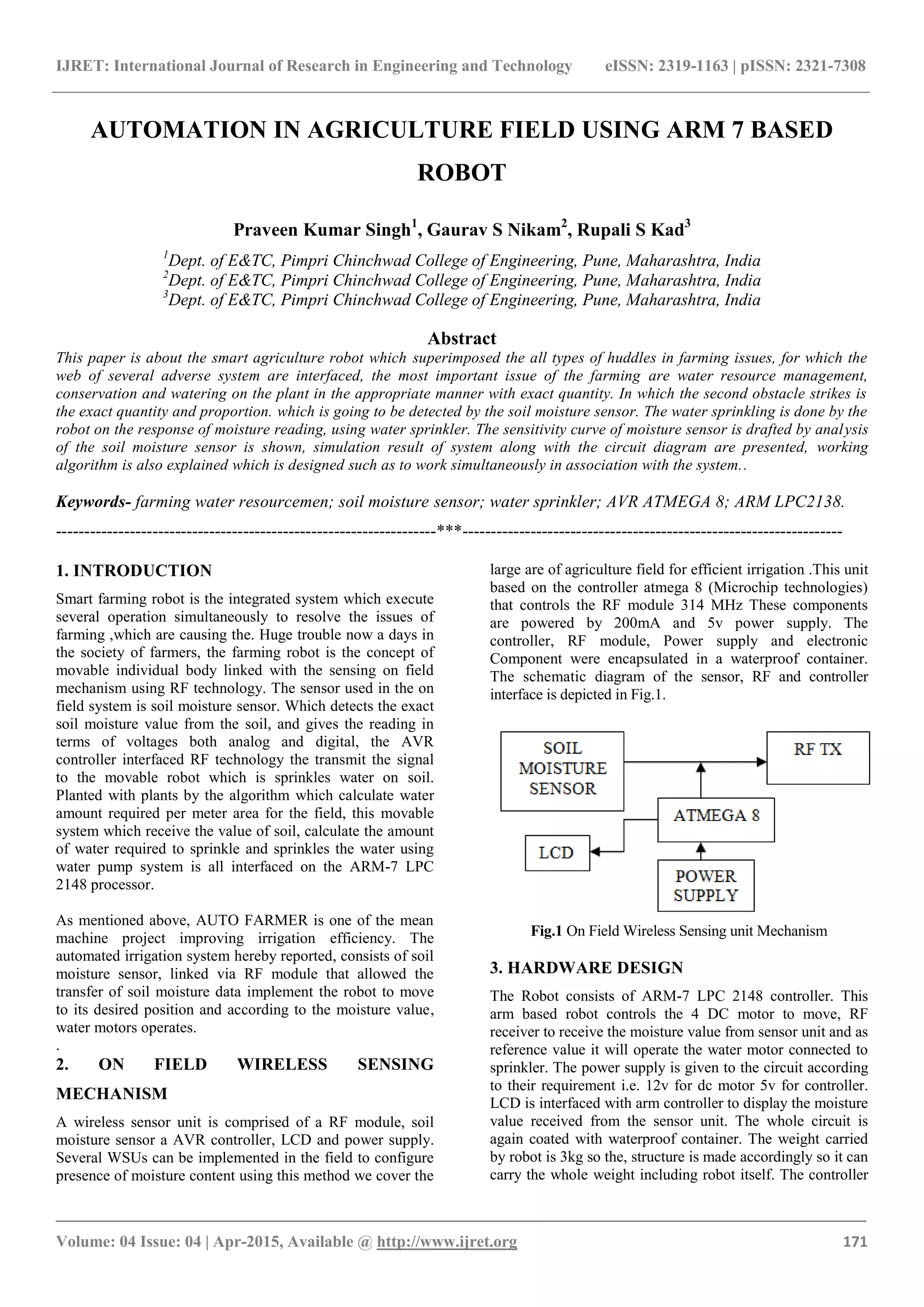
The document discusses the development of a smart agriculture robot designed to improve irrigation efficiency by automating water resource management through the use of a soil moisture sensor and ARM7 LPC2148 controller. The robot detects soil moisture levels, calculates the required water volume, and uses a water sprinkler system to irrigate crops as needed, reducing labor for farmers. The design includes hardware specifications, algorithms for operation, and testing results demonstrating the system's effectiveness in various soil moisture conditions.