Downloaded 631 times

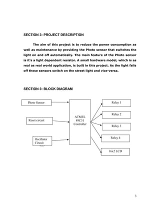


This document outlines a project to develop an automatic street light controller using an AT89c51 microcontroller. It will include a photo sensor that switches the street lights on and off based on light levels, reducing power consumption. The project description provides a block diagram and overview of the main components, including the microcontroller, photo sensor, relays to control the lights, and an LCD display. It also describes the interfaces that will be used, such as the sensor, LCD, relays, switches and LED, and the software needed like a compiler and downloader.