Transmitting audio signal using ir led.
other than audio we can also use melody generator(um66), in place of audio signal.
or we can use microphone in place of audio input.
and instead of ir receiver we can make use of photo transistor.
Timer with audible warning with circuit Diagram Team Kuk
From detectors to automobiles, audible alarms (also known to be called buzzers) have become a part of our everyday life. Some of the uses of these alarms are innocuous such as in a microwave oven. However, in some applications such as in a smoke detector or medical equipment, a person’s life may depend upon the audible warning sound. In all cases, the equipment designer should consider the desired characteristics of the audible alarm at the initial design-planning phase to obtain satisfactory performance and avoid costly redesign. The first characteristic for a designer to consider is the type of sound such as a continuous, intermittent or specialty sound. Other critical criteria include sound level, frequency, current draw, quality, mounting configuration, cost, and availability
The term amplifier refers to any device that increases the amplitude of a signal, usually measured in voltage or current. This versatile device is used in a variety of different electronic applications. Especially in audio technology, a wide range of amplifiers can be produced based on product specifications (i.e. power, voltage, current). Currently, there are many types of audio amplifiers available for consumers. Sound signal amplification is used for instruments, such as the guitar or the bass. They are also used commonly in home theater systems and with stereo speakers. The basic design behind all of these amplifiers is derived from the simplest concepts of circuit design.
For our project, we set out to design an audio amplifier. The inputs of our circuit were stereo signals from a portable music player. Although we used a low-power speaker, we needed to achieve approximately three times gain over the entire circuit. In addition, the amplifier had to be produced at a low cost with available materials. Before building the actual amplifier, we realized that we had to design, simulate, and test the circuit. Each step was necessary to understand the concepts involved in amplification
This project is a simple audio amplifier. It amplifies the audio signal to some extent. For amplifying purpose it used an IC and few more components. The heart of this amplifier is IC LM 386. The input to this circuit is given through the mobile phone or pc or any device which have 3.5mm connector.
This circuit has an extremely minimalistic design and only uses a few parts. By taking advantage of the LM683 amplifier ICs low power profile and high output the resulting amplifier provides quite a kick when it comes to volume.
It is a battery level indicator program which tells the level of the battery how much it is charged. It includes the proteus pics of the program. I tells the working of the circuit.
What it is: This is a circuit for a mobile transmission detector which can detect use of a mobile phone within the range of 1.5 meters. Whenever usage of mobile phone is detected such as calling or texting a beep alarm starts sounding and a led blinks.
Why it is: This handy, pocket-size mobile transmission detector can sense the presence of an activated mobile phone from a distance of one and a-half meters.
Where it is used: it can be used to prevent use of mobile phones in examination halls, confidential rooms, etc. It is also useful for detecting the use of mobile phone for spying and unauthorized video transmission.
This handy, it can be used to prevent use of mobile phones in examination halls, confidential rooms and, etc. It is also useful for detecting the use of mobile phone for Spying and unauthorized video transmission. The circuit can detect the incoming calls pocket-size mobile transmission detector or sniffer can sense the presence of an activated mobile cell phone from a distance of one and-a-half meters. So and also outgoing calls, SMS and video transmissions even if the mobile phone is kept in the silent mode. The moment the Bug detects RF transmission signal from an activated mobile phone, it starts sounding a beep alarm and the LED blinks. The alarm continues until the signal transmission ceases. The capacitor C3 should have a lead length of 18 mm with lead spacing of 8 mm. we have to carefully solder the capacitor in standing position with equal spacing of the leads. The response can be optimized by trimming the lead length of C3 for the desired frequency. We are using a short telescopic type antenna. The unit will give the warning indication if someone uses Mobile phone within a radius of 1.5 meters.
This handy, pocket-size mobile transmission detector or sniffer can sense the presence of an activated mobile cell phone from a distance of one and-a-half meters. So it can be used to prevent use of mobile phones in examination halls, confidential rooms, etc. It is also useful for detecting the use of mobile phone for Spying and unauthorized video transmission. The circuit can detect the incoming and outgoing calls, SMS and video transmission even if the mobile phone is kept in the silent mode. The moment the Bug detects RF transmission signal from an activated mobile phone, it starts sounding a beep alarm and the LED blinks. The alarm continues until the signal transmission ceases. Assemble the circuit on a general purpose PCB as compact as possible and enclose in a small box like junk mobile case. As mentioned earlier, capacitor C3 should have a lead length of 18 mm with lead spacing of 8 mm. Carefully solder the capacitor in standing position with equal spacing of the leads. The response can be optimized by trimming the lead length of C3 for the desired frequency. You may use a short telescopic type antenna.
Smart Autonomous Mobile detector RobotPunit Tiwari
SMART AUTONOMOUS MOBILE DETECTOR ROBOT
-This device can notice the use of GSM mobile phone in mobile restricted areas such as Examination hall or confidential rooms etc.
-It is just like a sniffer mobile that can sense the activity of mobile phone from a distance of 5 meters or more.
Smart Autonomous Mobile detector RobotPunit Tiwari
SMART AUTONOMOUS MOBILE DETECTOR ROBOT
-This device can notice the use of GSM mobile phone in mobile restricted areas such as Examination hall or confidential rooms etc..
-It is just like a sniffer mobile that can sense the activity of mobile phone from a distance of 5 meters or more.
A cell phone detector is a device which detects any cell phone at any examination hall,meetings and any other place whenever required. This is a very useful device in modern time whenever unwanted activities are growing due to cell phone. In this presentation we covered principle,components, working and assembling of all components including advantages of this device.
@ Mr. unique presentations
Li-Fi stands for Light-Fidelity. Li-Fi is transmission of data using visible light by sending data through an LED light bulb that varies in intensity faster than the human eye can follow. If the LED is on, the photo detector registers a binary one; otherwise it‟s a binary zero. The idea of Li-Fi was introduced by a German physicist, Harald Hass, which he also referred to as “Data
through Illumination”. The term Li-Fi was first used by Haas in his TED Global talk on Visible Light Communication. According to Hass, the light, which he referred to as „DLight‟, can be used to produce data rates higher than 1 Giga bits per second which is much faster than our average broadband connection.
This Project discusses the implementation of the most basic Li-Fi based system to
transmit Sound signal from one device to another through visible light. The purpose is to demonstrate only the working of the simplest model of Li-Fi with no major consideration about the data transfer speed. This model will demonstrate how the notion of one-way communication via visible light works, in which Light emitting diodes (LEDs) are employed as the light sources or Transmitter antennas. the sound is transferred by light and is detected at the receiver without fading.
All the applications of ferrites is described in this presentation very briefly and presciously.
It would surely help you.
Please share it with your friends also.
Abstract: An audio mixer amplifier is a device that translates a signal of one frequency band to another. It will accept many inputs at different frequencies and generate an output of the combination or sum of the frequencies. The mixer circuit provides good gain to weak audio signals. It can be used in front of an R.F. oscillator to make an R.F. receiver that is very sensitive to sound. Each input can be independently controlled by a variable resistor. There is also a provision for a balance control to fade out signal while simultaneously fading in the other. Key Words: Audio Mixer, Frequency, Signal, Circuit
accelerometer based gesture controlled robotic arm
Mobile bug
1. 1
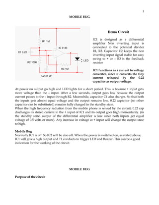
MOBILE BUG
Demo Circuit
R1 1M
IC 3130
C1 0.22
LED
R2 100K
R3 1M
IC1 is designed as a differential
amplifier Non inverting input is
connected to the potential divider
R1, R2. Capacitor C2 keeps the non
inverting input signal stable for easy
swing to + or – R3 is the feedback
resistor
IC1 functions as a current to voltage
converter, since it converts the tiny
current released by the 0.22
capacitor as output voltage.
C2 47 UF
At power on output go high and LED lights for a short period. This is because + input gets
more voltage than the – input. After a few seconds, output goes low because the output
current passes to the – input through R2. Meanwhile, capacitor C1 also charges. So that both
the inputs gets almost equal voltage and the output remains low. 0.22 capacitor (no other
capacitor can be substituted) remains fully charged in the standby state.
When the high frequency radiation from the mobile phone is sensed by the circuit, 0.22 cap
discharges its stored current to the + input of IC1 and its output goes high momentarily. (in
the standby state, output of the differential amplifier is low since both inputs get equal
voltage of 0.5 volts or more). Any increase in voltage at + input will change the output state
to high.
Mobile Bug
Normally IC1 is off. So IC2 will be also off. When the power is switched on, as stated above,
IC1 will give a high output and T1 conducts to trigger LED and Buzzer .This can be a good
indication for the working of the circuit.
MOBILE BUG
Purpose of the circuit
2. 2
This circuit is intended to detect unauthorized use of mobile phones in examination halls,
confidential rooms etc. It also helps to detect unauthorized video and audio recordings. It
detects the signal from mobile phones even if it is kept in the silent mode. It also detects SMS.
CONCEPT
Mobile phone uses RF with a wavelength of 30cm at 872 to 2170 MHz. That is the signal is
high frequency with huge energy. When the mobile phone is active, it transmits the signal in
the form of sine wave which passes through the space. The encoded audio/video signal
contains electromagnetic radiation which is picked up by the receiver in the base station.
Mobile phone system is referred to as “Cellular Telephone system” because the coverage area
is divided into “cells” each of which has a base station. The transmitter power of the modern
2G antenna in the base station is 20-100 watts.
When a GSM (Global System of Mobile communication) digital phone is transmitting, the
signal is time shared with 7 other users. That is at any one second, each of the 8 users on the
same frequency is allotted 1/8 of the time and the signal is reconstituted by the receiver to
form the speech. Peak power output of a mobile phone corresponds to 2 watts with an
average of 250 milli watts of continuous power. Each handset with in a ‘cell’ is allotted a
particular frequency for its use. The mobile phone transmits short signals at regular intervals
to register its availability to the nearest base station. The network data base stores the
information transmitted by the mobile phone. If the mobile phone moves from one cell to
another, it will keep the connection with the base station having strongest transmission.
Mobile phone always tries to make connection with the available base station. That is why,
the back light of the phone turns on intermittently while traveling. This will cause severe
battery drain. So in long journeys, battery will flat with in a few hours.
AM Radio uses frequencies between 180 kHz and 1.6 MHz. FM radio uses 88 to 180 MHz. TV
uses 470 to 854 MHz. Waves at higher frequencies but with in the RF region is called Micro
waves. Mobile phone uses high frequency RF wave in the micro wave region carrying huge
amount of electromagnetic energy. That is why burning sensation develops in the ear if the
mobile is used for a long period. Just like a micro wave oven, mobile phone is ‘cooking’ the
tissues in the ear. RF radiation from the phone causes oscillation of polar molecules like
water in the tissues. This generates heat through friction just like the principle of microwave
oven. The strongest radiation from the mobile phone is about 2 watts which can make
connection with a base station located 2 to 3 km away.
How the circuit works?
Ordinary LC (Coil-Capacitor) circuits are used to detect low frequency radiation in the AM
and FM bands. The tuned tank circuit having a coil and a variable capacitor retrieve the
signal from the carrier wave. But such LC circuits cannot detect high frequency waves near
the microwave region. Hence in the circuit, a capacitor is used to detect RF from mobile
phone considering that, a capacitor can store energy even from an outside source and
oscillate like LC circuit.
3. 3
R5 100R
R1 3.9 M
3
C
0.22 UF
R2
100K
IC1
2
C1
100
UF
25V
LED
Red
IC1
CA 3130
7
6
BUZZER
R4 100 R
+
9 V Battery
4
R3 1 M
C2
0.1
Use of capacitor
A capacitor has two electrodes separated by a ‘dielectric’ like paper, mica etc. The non
polarized disc capacitor is used to pass AC and not DC. Capacitor can store energy and pass
AC signals during discharge. 0.22 capacitor is selected because it is a low value one and has
large surface area to accept energy from the mobile radiation. To detect the signal, the sensor
part should be like an aerial. So the capacitor is arranged as a mini loop aerial (similar to the
dipole antenna used in TV).In short with this arrangement, the capacitor works like an air
core coil with ability to oscillate and discharge current.
How the capacitor senses RF?
One lead of the capacitor gets DC from the positive rail and the other lead goes to the
negative input of IC1. So the capacitor gets energy for storage. This energy is applied to the
inputs of IC1 so that the inputs of IC are almost balanced with 1.4 volts. In this state output is
zero. But at any time IC can give a high output if a small current is induced to its inputs.
There a natural electromagnetic field around the capacitor caused by the 50Hz from electrical
wiring. When the mobile phone radiates high energy pulsations, capacitor oscillates and
release energy in the inputs of IC. This oscillation is indicated by the flashing of the LED and
beeping of Buzzer. In short, capacitor carries energy and is in an electromagnetic field. So a
slight change in field caused by the RF from phone will disturb the field and forces the
capacitor to release energy.
ROLE OF IC CA 3130
This IC is a 15 MHz BiMOS Operational amplifier with MOSFET inputs and Bipolar output.
The inputs contain MOSFET transistors to provide very high input impedance and very low
input current as low as 10pA. It has high speed of performance and suitable for low input
current applications.
RANGE OF THE CIRCUIT
The prototype version has only limited range of 2 meters. But if a preamplifier stage using
JFET or MOSFET transistor is used as an interface between the capacitor and IC, range can be
increased.