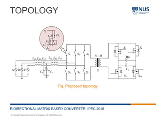
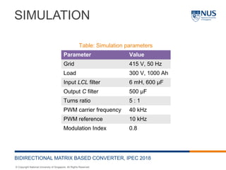
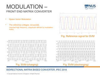
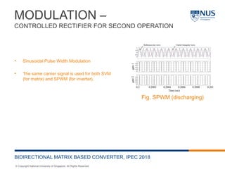
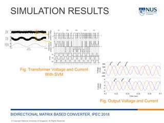
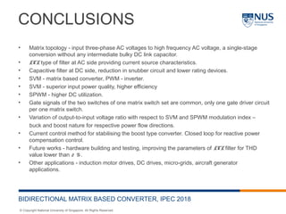
© Copyright National University of Singapore. All Rights Reserved.
A MATRIX BASED ISOLATED
BIDIRECTIONAL AC-DC CONVERTER WITH
LCL TYPE INPUT FILTER FOR ENERGY
STORAGE APPLICATION
Prathamesh Pravin Deshpande*, Amit Kumar Singh, Sanjib Kumar Panda
Department of Electrical and Computer Engineering, National University of Singapore,
Singapore
*eledpp@nus.edu.sg
International Power Electronics Conference, 2018
© Copyright National University of Singapore. All Rights Reserved.
OUTLINE
1. Introduction
2. Proposed Topology
3. Operation
4. Simulation and Results
5. Closed loop operation with simulation results
6. Conclusion
BIDIRECTIONAL MATRIX BASED CONVERTER, IPEC 2018
© Copyright National University of Singapore. All Rights Reserved.
INTRODUCTION
• Advantages of galvanic isolation, voltage control
• Various modulation schemes like Sinusoidal Pulse Width Modulation (SPWM), Space
Vector Modulation (SVM).
• SVM, advantages of lower input current THD, lower duty-cycle loss, maximum output
inductor current ripple and minimum switching loss comparing to other PWM
schemes
• Filter (cut-off frequency lower than switching frequency (low pass)), to minimize size
of capacitors and inductors and minimizing filter inductor voltage drop or impedance
at rated current.
BIDIRECTIONAL MATRIX BASED CONVERTER, IPEC 2018
© Copyright National University of Singapore. All Rights Reserved.
INTRODUCTION
• A matrix based converter - multi-phase-to-multi-phase AC-AC converter with an array
of switches.
• To convert low frequency AC to high frequency AC.
• Overcomes the limitations expressed for conventional converters like DC link
capacitor with reduced current distortion and improved power conversion efficiency.
• Higher modulation index, higher input power quality and lower semiconductor losses.
• Suitable for aircraft system, telecommunication, micro-grid and energy storage.
• The implication in bidirectional power flow mode.
• For input LC filter, an output inductor filter is required, a comprehensive modulation
technique is required for matrix based converter to reduce Total Harmonic Distortion
(THD) for bidirectional operation.
BIDIRECTIONAL MATRIX BASED CONVERTER, IPEC 2018
Sx
G
Sy
Dx
Dy
x
y
AC AC
© Copyright National University of Singapore. All Rights Reserved.
CONTRIBUTIONS
• Use of three-phase LCL (T-shaped) filter, to provide inductive dominance from either
terminals.
• The proposed SVM based modulation scheme requires single control for each of the
matrix switches and therefore, no body diode conduction with reduced number of
isolated gate drivers (six for six matrix switches).
• Use of full bridge controlled rectifier to perform AC-DC as well as DC-AC operations.
Synchronous rectification to provide lower conduction losses and a simple control
technique like SPWM could be used for inversion operation.
BIDIRECTIONAL MATRIX BASED CONVERTER, IPEC 2018
© Copyright National University of Singapore. All Rights Reserved.
TOPOLOGY
BIDIRECTIONAL MATRIX BASED CONVERTER, IPEC 2018
3-ph
AC
AC/DC DC/AC AC/DC Storage
3-ph
AC
AC/AC
AC/DC Storage
Traditional topology
Proposed topology
Sx
G
Sy
Dx
Dy
x
y
T
1 : 1
T
1 : 1
© Copyright National University of Singapore. All Rights Reserved.
TOPOLOGY
BIDIRECTIONAL MATRIX BASED CONVERTER, IPEC 2018
Fig. Proposed topology
© Copyright National University of Singapore. All Rights Reserved.
LCL TYPE LOW PASS FILTER
BIDIRECTIONAL MATRIX BASED CONVERTER, IPEC 2018
• Gain margin = 27.4 dB at 745 rad/sec
• Phase margin = 13.3 deg at 726 rad/sec
• The resonance peak = 115Hz
Fig. Filter circuit for analysis
Fig. Bode plot for LCL filter
2
2 2 1
2 2 4 2 3 2
1 1 2 1 2 1 1 2 1 2 1
2
22
1 2 1 2
1
2
1 1 1
2 2 4 2 3 2
2 1 2 1 1 1 1 2 1 1 2
( ) ( ) 1
( ) ( ) ( ) (2 ) ( ) ( )
( ) 1
( ) 1
( ) ( )
( ) ( ) 1
( ) ( ) ( ) (2 ) ( ) ( )
i s L C s
v s L L C s L C s L L C s L s L
i s
v s
L L s L L
C
i s L C s
v s L L C s L C s L L C s L s L
+
=
+ + + +
=
 
+ + ÷
 
+
=
+ + + +
© Copyright National University of Singapore. All Rights Reserved.
OPERATION
BIDIRECTIONAL MATRIX BASED CONVERTER, IPEC 2018
• Charging of the energy storage using the utility grid
• Power flows from the utility grid to the energy storage device.
• The full bridge controlled rectifier acts as rectifier to convert the high frequency AC to DC (the
body or antiparallel diodes or synchronous rectification technique).
• SVM for matrix based converter.
• Desired high frequency AC signal = reference sine wave for SVM.
• Discharging of the energy storage to the utility grid
• Power flows from the energy storage device to the utility grid.
• The full bridge controlled rectifier acts as inverter to convert DC to high frequency AC.
• SVM is used for the matrix based converter.
• SPWM is used for the inverter.
• Desired high frequency AC signal = reference sine wave for SPWM.
• Line frequency AC signal = reference sine wave for SVM.
© Copyright National University of Singapore. All Rights Reserved.
SIMULATION
BIDIRECTIONAL MATRIX BASED CONVERTER, IPEC 2018
Parameter Value
Grid 415 V, 50 Hz
Load 300 V, 1000 Ah
Input LCL filter 6 mH, 600 µF
Output C filter 500 µF
Turns ratio 5 : 1
PWM carrier frequency 40 kHz
PWM reference 10 kHz
Modulation Index 0.8
Table: Simulation parameters
© Copyright National University of Singapore. All Rights Reserved.
MODULATION –
FRONT END MATRIX CONVERTER
BIDIRECTIONAL MATRIX BASED CONVERTER, IPEC 2018
• Space Vector Modulation
• The reference voltages: sinusoidal,
(required high frequency, magnitude defined by modulation
index)
Fig. SVM (charging) Fig. SVM (discharging)
Fig. Reference signal for SVM
© Copyright National University of Singapore. All Rights Reserved.
MODULATION –
CONTROLLED RECTIFIER FOR SECOND OPERATION
BIDIRECTIONAL MATRIX BASED CONVERTER, IPEC 2018
• Sinusoidal Pulse Width Modulation
• The same carrier signal is used for both SVM
(for matrix) and SPWM (for inverter).
Fig. SPWM (discharging)
© Copyright National University of Singapore. All Rights Reserved.
SIMULATION RESULTS –
CHARGING
BIDIRECTIONAL MATRIX BASED CONVERTER, IPEC 2018
Fig. Grid Voltage and Current
Fig. Battery Charging Voltage and Current
Fig. Transformer Voltage and Current
THDi = 2 %
© Copyright National University of Singapore. All Rights Reserved.
SIMULATION RESULTS –
DISCHARGING
BIDIRECTIONAL MATRIX BASED CONVERTER, IPEC 2018
Fig. Output Voltage and Current
THDi = 2 %
© Copyright National University of Singapore. All Rights Reserved.
CLOSED LOOP OPERATION
BIDIRECTIONAL MATRIX BASED CONVERTER, IPEC 2018
Fig. Proposed topology
abc
abc
vd
i
dt L
∆
=
( )d
d q
vd
i i
dt L
ω
∆
= + ( )d d dv u e∆ = −
( ) ( )d d d q
d
u e L i L i
dt
ω∴ = + −
( ) ( )q q q d
d
u e L i L i
dt
ω= + +
( ) ( )dq dq dq dq
d
u e L i j L i
dt
ω∴ = + +
Fig. Proposed topology
Using abc - dq transformation
Where,
Similarly,
Combining d and q components,
© Copyright National University of Singapore. All Rights Reserved.
SIMULATION RESULTS
BIDIRECTIONAL MATRIX BASED CONVERTER, IPEC 2018
Fig. Transformer Voltage and Current
With SVM
Fig. Output Voltage and Current
© Copyright National University of Singapore. All Rights Reserved.
RESULTS AND DISCUSSIONS
BIDIRECTIONAL MATRIX BASED CONVERTER, IPEC 2018
Fig. Variation of voltage ratio
or gain with respect to SVM
modulation index
Fig. Variation of voltage ratio
or gain with respect to SVM
(m) and SPWM modulation
index (M)
© Copyright National University of Singapore. All Rights Reserved.
CONCLUSIONS
BIDIRECTIONAL MATRIX BASED CONVERTER, IPEC 2018
• Matrix topology - input three-phase AC voltages to high frequency AC voltage, a single-stage
conversion without any intermediate bulky DC link capacitor.
• LCL type of filter at AC side providing current source characteristics.
• Capacitive filter at DC side, reduction in snubber circuit and lower rating devices.
• SVM - matrix based converter, PWM - inverter.
• SVM - superior input power quality, higher efficiency
• SPWM - higher DC utilization.
• Gate signals of the two switches of one matrix switch set are common, only one gate driver circuit
per one matrix switch.
• Variation of output-to-input voltage ratio with respect to SVM and SPWM modulation index –
buck and boost nature for respective power flow directions.
• Current control method for stabilising the boost type converter. Closed loop for reactive power
compensation control.
• Future works - hardware building and testing, improving the parameters of LCL filter for THD
value lower than 2 % .
• Other applications - induction motor drives, DC drives, micro-grids, aircraft generator
applications.
© Copyright National University of Singapore. All Rights Reserved.
THANK YOU

Matrix based AC-DC converter

  • 1.
    © Copyright NationalUniversity of Singapore. All Rights Reserved. A MATRIX BASED ISOLATED BIDIRECTIONAL AC-DC CONVERTER WITH LCL TYPE INPUT FILTER FOR ENERGY STORAGE APPLICATION Prathamesh Pravin Deshpande*, Amit Kumar Singh, Sanjib Kumar Panda Department of Electrical and Computer Engineering, National University of Singapore, Singapore *eledpp@nus.edu.sg International Power Electronics Conference, 2018
  • 2.
    © Copyright NationalUniversity of Singapore. All Rights Reserved. OUTLINE 1. Introduction 2. Proposed Topology 3. Operation 4. Simulation and Results 5. Closed loop operation with simulation results 6. Conclusion BIDIRECTIONAL MATRIX BASED CONVERTER, IPEC 2018
  • 3.
    © Copyright NationalUniversity of Singapore. All Rights Reserved. INTRODUCTION • Advantages of galvanic isolation, voltage control • Various modulation schemes like Sinusoidal Pulse Width Modulation (SPWM), Space Vector Modulation (SVM). • SVM, advantages of lower input current THD, lower duty-cycle loss, maximum output inductor current ripple and minimum switching loss comparing to other PWM schemes • Filter (cut-off frequency lower than switching frequency (low pass)), to minimize size of capacitors and inductors and minimizing filter inductor voltage drop or impedance at rated current. BIDIRECTIONAL MATRIX BASED CONVERTER, IPEC 2018
  • 4.
    © Copyright NationalUniversity of Singapore. All Rights Reserved. INTRODUCTION • A matrix based converter - multi-phase-to-multi-phase AC-AC converter with an array of switches. • To convert low frequency AC to high frequency AC. • Overcomes the limitations expressed for conventional converters like DC link capacitor with reduced current distortion and improved power conversion efficiency. • Higher modulation index, higher input power quality and lower semiconductor losses. • Suitable for aircraft system, telecommunication, micro-grid and energy storage. • The implication in bidirectional power flow mode. • For input LC filter, an output inductor filter is required, a comprehensive modulation technique is required for matrix based converter to reduce Total Harmonic Distortion (THD) for bidirectional operation. BIDIRECTIONAL MATRIX BASED CONVERTER, IPEC 2018 Sx G Sy Dx Dy x y AC AC
  • 5.
    © Copyright NationalUniversity of Singapore. All Rights Reserved. CONTRIBUTIONS • Use of three-phase LCL (T-shaped) filter, to provide inductive dominance from either terminals. • The proposed SVM based modulation scheme requires single control for each of the matrix switches and therefore, no body diode conduction with reduced number of isolated gate drivers (six for six matrix switches). • Use of full bridge controlled rectifier to perform AC-DC as well as DC-AC operations. Synchronous rectification to provide lower conduction losses and a simple control technique like SPWM could be used for inversion operation. BIDIRECTIONAL MATRIX BASED CONVERTER, IPEC 2018
  • 6.
    © Copyright NationalUniversity of Singapore. All Rights Reserved. TOPOLOGY BIDIRECTIONAL MATRIX BASED CONVERTER, IPEC 2018 3-ph AC AC/DC DC/AC AC/DC Storage 3-ph AC AC/AC AC/DC Storage Traditional topology Proposed topology Sx G Sy Dx Dy x y T 1 : 1 T 1 : 1
  • 7.
    © Copyright NationalUniversity of Singapore. All Rights Reserved. TOPOLOGY BIDIRECTIONAL MATRIX BASED CONVERTER, IPEC 2018 Fig. Proposed topology
  • 8.
    © Copyright NationalUniversity of Singapore. All Rights Reserved. LCL TYPE LOW PASS FILTER BIDIRECTIONAL MATRIX BASED CONVERTER, IPEC 2018 • Gain margin = 27.4 dB at 745 rad/sec • Phase margin = 13.3 deg at 726 rad/sec • The resonance peak = 115Hz Fig. Filter circuit for analysis Fig. Bode plot for LCL filter 2 2 2 1 2 2 4 2 3 2 1 1 2 1 2 1 1 2 1 2 1 2 22 1 2 1 2 1 2 1 1 1 2 2 4 2 3 2 2 1 2 1 1 1 1 2 1 1 2 ( ) ( ) 1 ( ) ( ) ( ) (2 ) ( ) ( ) ( ) 1 ( ) 1 ( ) ( ) ( ) ( ) 1 ( ) ( ) ( ) (2 ) ( ) ( ) i s L C s v s L L C s L C s L L C s L s L i s v s L L s L L C i s L C s v s L L C s L C s L L C s L s L + = + + + + =   + + ÷   + = + + + +
  • 9.
    © Copyright NationalUniversity of Singapore. All Rights Reserved. OPERATION BIDIRECTIONAL MATRIX BASED CONVERTER, IPEC 2018 • Charging of the energy storage using the utility grid • Power flows from the utility grid to the energy storage device. • The full bridge controlled rectifier acts as rectifier to convert the high frequency AC to DC (the body or antiparallel diodes or synchronous rectification technique). • SVM for matrix based converter. • Desired high frequency AC signal = reference sine wave for SVM. • Discharging of the energy storage to the utility grid • Power flows from the energy storage device to the utility grid. • The full bridge controlled rectifier acts as inverter to convert DC to high frequency AC. • SVM is used for the matrix based converter. • SPWM is used for the inverter. • Desired high frequency AC signal = reference sine wave for SPWM. • Line frequency AC signal = reference sine wave for SVM.
  • 10.
    © Copyright NationalUniversity of Singapore. All Rights Reserved. SIMULATION BIDIRECTIONAL MATRIX BASED CONVERTER, IPEC 2018 Parameter Value Grid 415 V, 50 Hz Load 300 V, 1000 Ah Input LCL filter 6 mH, 600 µF Output C filter 500 µF Turns ratio 5 : 1 PWM carrier frequency 40 kHz PWM reference 10 kHz Modulation Index 0.8 Table: Simulation parameters
  • 11.
    © Copyright NationalUniversity of Singapore. All Rights Reserved. MODULATION – FRONT END MATRIX CONVERTER BIDIRECTIONAL MATRIX BASED CONVERTER, IPEC 2018 • Space Vector Modulation • The reference voltages: sinusoidal, (required high frequency, magnitude defined by modulation index) Fig. SVM (charging) Fig. SVM (discharging) Fig. Reference signal for SVM
  • 12.
    © Copyright NationalUniversity of Singapore. All Rights Reserved. MODULATION – CONTROLLED RECTIFIER FOR SECOND OPERATION BIDIRECTIONAL MATRIX BASED CONVERTER, IPEC 2018 • Sinusoidal Pulse Width Modulation • The same carrier signal is used for both SVM (for matrix) and SPWM (for inverter). Fig. SPWM (discharging)
  • 13.
    © Copyright NationalUniversity of Singapore. All Rights Reserved. SIMULATION RESULTS – CHARGING BIDIRECTIONAL MATRIX BASED CONVERTER, IPEC 2018 Fig. Grid Voltage and Current Fig. Battery Charging Voltage and Current Fig. Transformer Voltage and Current THDi = 2 %
  • 14.
    © Copyright NationalUniversity of Singapore. All Rights Reserved. SIMULATION RESULTS – DISCHARGING BIDIRECTIONAL MATRIX BASED CONVERTER, IPEC 2018 Fig. Output Voltage and Current THDi = 2 %
  • 15.
    © Copyright NationalUniversity of Singapore. All Rights Reserved. CLOSED LOOP OPERATION BIDIRECTIONAL MATRIX BASED CONVERTER, IPEC 2018 Fig. Proposed topology abc abc vd i dt L ∆ = ( )d d q vd i i dt L ω ∆ = + ( )d d dv u e∆ = − ( ) ( )d d d q d u e L i L i dt ω∴ = + − ( ) ( )q q q d d u e L i L i dt ω= + + ( ) ( )dq dq dq dq d u e L i j L i dt ω∴ = + + Fig. Proposed topology Using abc - dq transformation Where, Similarly, Combining d and q components,
  • 16.
    © Copyright NationalUniversity of Singapore. All Rights Reserved. SIMULATION RESULTS BIDIRECTIONAL MATRIX BASED CONVERTER, IPEC 2018 Fig. Transformer Voltage and Current With SVM Fig. Output Voltage and Current
  • 17.
    © Copyright NationalUniversity of Singapore. All Rights Reserved. RESULTS AND DISCUSSIONS BIDIRECTIONAL MATRIX BASED CONVERTER, IPEC 2018 Fig. Variation of voltage ratio or gain with respect to SVM modulation index Fig. Variation of voltage ratio or gain with respect to SVM (m) and SPWM modulation index (M)
  • 18.
    © Copyright NationalUniversity of Singapore. All Rights Reserved. CONCLUSIONS BIDIRECTIONAL MATRIX BASED CONVERTER, IPEC 2018 • Matrix topology - input three-phase AC voltages to high frequency AC voltage, a single-stage conversion without any intermediate bulky DC link capacitor. • LCL type of filter at AC side providing current source characteristics. • Capacitive filter at DC side, reduction in snubber circuit and lower rating devices. • SVM - matrix based converter, PWM - inverter. • SVM - superior input power quality, higher efficiency • SPWM - higher DC utilization. • Gate signals of the two switches of one matrix switch set are common, only one gate driver circuit per one matrix switch. • Variation of output-to-input voltage ratio with respect to SVM and SPWM modulation index – buck and boost nature for respective power flow directions. • Current control method for stabilising the boost type converter. Closed loop for reactive power compensation control. • Future works - hardware building and testing, improving the parameters of LCL filter for THD value lower than 2 % . • Other applications - induction motor drives, DC drives, micro-grids, aircraft generator applications.
  • 19.
    © Copyright NationalUniversity of Singapore. All Rights Reserved. THANK YOU